Danfoss VLT DriveMotor FCP 106 Installation Manual
Hide thumbs
Also See for VLT DriveMotor FCP 106:
- Programming manual (148 pages) ,
- Design manual (82 pages) ,
- Operating instructions manual (62 pages)
Advertisement
Available languages
Available languages
Quick Links
Installation Guide • Installationshandbuch • Manuel d'installation • Guía de instalación • Guida di installazione •
Guia de Instalação
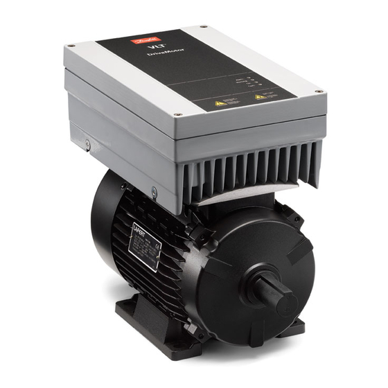
VLT® DriveMotor FCP 106
Scan to access more
Scan to access more
documentation
vlt-drives.danfoss.com
Advertisement

Related Manuals for Danfoss VLT DriveMotor FCP 106


Summary of Contents for Danfoss VLT DriveMotor FCP 106
- Page 1 Installation Guide • Installationshandbuch • Manuel d'installation • Guía de instalación • Guida di installazione • Guia de Instalação VLT® DriveMotor FCP 106 Scan to access more Scan to access more documentation vlt-drives.danfoss.com...
- Page 3 Installation Guide | VLT® DriveMotor FCP 106 Languages Languages American English German French Spanish Italian Brazilian Portuguese AN40855215838601-000101 / 130R1249 | 3 Danfoss A/S © 2022.09...
- Page 4 Installation Guide | VLT® DriveMotor FCP 106 Languages 4 | Danfoss A/S © 2022.09 AN40855215838601-000101 / 130R1249...
- Page 5 Non-skilled electricians are not allowed to perform any elec- trical installation and troubleshooting activities. Only Danfoss authorized, skilled personnel are allowed to repair this equipment. Further training is required to perform the activi- ties related to repair.
- Page 6 Failure to run output motor cables separately, or to use shielded cables, could result in death or serious injury. Run output motor cables separately or use shielded cables. Simultaneously lock out/tag out all the drives. 6 | Danfoss A/S © 2022.09 AN40855215838601-000101 / 130R1249...
- Page 7 Keep all doors, covers, and terminal boxes closed and securely fastened during operation. 1.7 Verifying the Shipment and the Contents Make sure that the items supplied and the information on the nameplate on the drive exterior match the order. Danfoss A/S © 2022.09 AN40855215838601-000101 / 130R1249 | 7...
- Page 8 Avoid installation with twisted shield ends (pigtails), since this type of installation ruins the shield effect at high frequencies. Use the cable clamps provided instead. • Ensure the same potential between drive and ground potential of the PLC. • Use star washers and galvanically conductive installation plates. 8 | Danfoss A/S © 2022.09 AN40855215838601-000101 / 130R1249...
- Page 9 Attach control and relay terminals, see step 6 in the Illustrations section. Reassemble the cover and tighten the screws. 1.12 Power Losses and Efficiency For power loss data including part load losses, see https://ecosmart.mydrive.danfoss.com. 1.13 Fuses and Cable Sizes N O T I C E WIRING GUIDELINES All wiring must comply with local and national regulations regarding cross-section and ambient temperature requirements.
- Page 10 Anleitungen vertraut sein. Nicht speziell geschulte Fachelektriker dürfen weder Arbeiten an der elektrischen Installation noch Feh- lersuche und -behebung durchführen. Dieses Gerät darf nur von Danfoss autorisiertem, qualifiziertem Fachpersonal repariert werden. Für die Durchführung der Tätigkeit- en im Zusammenhang mit der Reparatur sind weitere Schulungen erforderlich.
- Page 11 Stellen Sie vor dem Anlegen von Netzspannung sicher, dass alle Sicherheitsabdeckungen angebracht und ordnungsgemäß befestigt sind. 1.5 Allgemeine Vorsichtsmaßnahmen bei der elektrischen Installation Vor dem Beginn von Elektroarbeiten am Frequenzumrichter sind alle Stromquellen vom Frequenzumrichter zu trennen, abzusper- ren und zu kennzeichnen (Lockout/Tagout). Danfoss A/S © 2022.09 AN40855215838601-000101 / 130R1249 | 11...
- Page 12 B. einen Kurzschlussschutz oder einen thermischen Motorschutz. Der Kurzschluss- und Überspannungsschutz wird durch Sicherungen am Eingang gewährleistet. Wenn die Sicherungen nicht Bestandteil der Lieferung ab Werk sind, muss sie der Installateur als Teil der Installation bereitstellen. 12 | Danfoss A/S © 2022.09 AN40855215838601-000101 / 130R1249...
- Page 13 1 Dichtung für den Einsatz zwischen Motoradapterplatte und Frequenzumrichter • 1 Motorstecker • 4 Schrauben zur Befestigung des Frequenzumrichters an der Adapterplatte • 4 Schrauben zur Befestigung der Motoradapterplatte am Motor • Crimpklemmen Danfoss A/S © 2022.09 AN40855215838601-000101 / 130R1249 | 13...
- Page 14 Schließen Sie das Netzkabel an den Klemmen L1, L2 und L3 an und ziehen Sie die Schrauben fest, siehe Schritt 5.2 im Ab- schnitt Abbildungen. Bringen Sie die Steuer- und Relaisklemmen an, siehe Schritt 6 im Abschnitt Abbildungen. Montieren Sie die Abdeckung wieder und ziehen Sie die Schrauben fest. 14 | Danfoss A/S © 2022.09 AN40855215838601-000101 / 130R1249...
- Page 15 VLT® DriveMotor FCP 106 Guide d'installation Instructions 1.12 Leistungsverluste und Wirkungsgrad Informationen zu Leistungsverlusten, inklusive Teillastverlusten, finden Sie unter https://ecosmart.mydrive.danfoss.com. 1.13 Sicherungen und Kabelquerschnitte H I N W E I S VERDRAHTUNGSRICHTLINIEN In Bezug auf Querschnitte und Umgebungstemperaturen müssen alle Leitungen lokale und nationale Vorschriften erfüllen. Lock- ere oder lose Anschlüsse können zu Gerätefehlern oder Leistungseinbußen führen.
- Page 16 Avant d’appliquer de la puissance, s’assurer que tous les caches de sécurité sont en place et fermement fixés. 1.5 Précautions relatives à l’installation électrique Avant de commencer des travaux d’électricité sur le variateur, verrouiller et étiqueter toutes les sources d’alimentation du variateur. 16 | Danfoss A/S © 2022.09 AN40855215838601-000101 / 130R1249...
- Page 17 A T T E N T I O N ISOLATION THERMISTANCE Risque de blessures ou de dommages à l’équipement. Pour satisfaire aux exigences d’isolation PELV, utiliser uniquement des thermistances à isolation renforcée ou double. Danfoss A/S © 2022.09 AN40855215838601-000101 / 130R1249 | 17...
- Page 18 * 1 3 1 U 3 9 3 0 0 1 0 1 0 2 G 2 9 0 * Illustration 1: Exemple de code de type sur la plaque signalétique 18 | Danfoss A/S © 2022.09 AN40855215838601-000101 / 130R1249...
- Page 19 Sertir les fils pour PE, les bornes du moteur U, V, W et les thermistances M et M , voir l’étape 2.1 de la section Illustrations. Installer le joint entre le moteur et le support du moteur, voir l’étape 2.2 de la section Illustrations. Danfoss A/S © 2022.09 AN40855215838601-000101 / 130R1249 | 19...
- Page 20 Remonter le capot et serrer les vis. 1.12 Pertes de puissance et efficacité Pour les données de perte de puissance, y compris les pertes à charge partielle, voir https://ecosmart.mydrive.danfoss.com. 1.13 Fusibles et sections de câble R E M A R Q U E INSTRUCTIONS DE CÂBLAGE...
- Page 21 VLT® DriveMotor FCP 106 Guía de instalación Instrucciones Solo el personal cualificado y autorizado de Danfoss puede reparar este equipo. Se requiere una capacitación adicional para reali- zar las actividades relacionadas con la reparación. 1.3 Símbolos de seguridad P E L I G R O Indica situaciones peligrosas que, si no se evitan, producirán lesiones graves e incluso la muerte.
- Page 22 No colocar separados los cables de salida del motor o no utilizar cables apantallados puede provocar lesiones graves o incluso la muerte. Coloque los cables de motor de salida separados o utilice cables apantallados. Bloquee/etiquete todos los convertidores de frecuencia de forma simultánea. 22 | Danfoss A/S © 2022.09 AN40855215838601-000101 / 130R1249...
- Page 23 • Mantenga todas las puertas, cubiertas y cajas de terminales cerradas y bien fijadas durante el funcionamiento de la unidad. Danfoss A/S © 2022.09 AN40855215838601-000101 / 130R1249 | 23...
- Page 24 Evite una instalación con extremos de apantallamiento trenzados (cables de pantalla retorcidos y embornados), ya que dicha instalación anulará el efecto de apantallamiento a altas frecuencias. Utilice en su lugar las abrazaderas de cable suministradas. 24 | Danfoss A/S © 2022.09 AN40855215838601-000101 / 130R1249...
- Page 25 Para la conexión de potencia, utilice cable de cobre para una temperatura nominal mínima de 70 °C (158 °F). Para los cables de aluminio, consulte la Guía de diseño. Danfoss A/S © 2022.09 AN40855215838601-000101 / 130R1249 | 25...
- Page 26 Gli elettricisti non qualificati non sono autorizzati a eseguire installazioni elettriche e attività di risoluzione dei problemi. Solo il personale Danfoss autorizzato e qualificato può riparare questa apparecchiatura. È necessaria un'ulteriore formazione per eseguire le attività relative alla riparazione.
- Page 27 Prima di applicare la corrente elettrica, assicurarsi che tutte le coperture di sicurezza siano al loro posto e fissate in modo sicuro. 1.5 Precauzioni per l'installazione elettrica Prima di iniziare un lavoro elettrico sul convertitore di frequenza, bloccare e segnalare tutte le fonti di alimentazione al convertitore stesso. Danfoss A/S © 2022.09 AN40855215838601-000101 / 130R1249 | 27...
- Page 28 A T T E N Z I O N E ISOLAMENTO TERMISTORE Rischio di lesioni personali o di danni alle apparecchiature. Per soddisfare i requisiti di isolamento PELV, utilizzare solo termistori con isolamento rinforzato o doppio. 28 | Danfoss A/S © 2022.09 AN40855215838601-000101 / 130R1249...
- Page 29 Tensione, frequenza e corrente di uscita (a basse/ Grado di protezione alte tensioni) Codice a barre per il produttore Tensione, frequenza e corrente di ingresso (a basse/ alte tensioni) Certificazioni Potenza nominale Numero seriale Codice Danfoss A/S © 2022.09 AN40855215838601-000101 / 130R1249 | 29...
- Page 30 Collegare i fili crimpati al connettore del motore, vedere il punto 2.6 nella sezione Illustrazioni. Collegare il connettore del motore al VLT® DriveMotor, vedere il punto 2.7 nella sezione Illustrazioni. Serrare il VLT® DriveMotor al motore. AN40855215838601-000101 / 130R1249 30 | Danfoss A/S © 2022.09...
- Page 31 Collegare i morsetti di controllo e i morsetti relè (vedere il punto 6 nella sezione Illustrazioni). Rimontare il coperchio e serrare le viti. 1.12 Perdite di potenza ed efficienza Per i dati sulle perdite di potenza, quali le perdite di carico parziali, vedere https://ecosmart.mydrive.danfoss.com. 1.13 Fusibili e dimensioni dei cavi N O T A...
- Page 32 Desconecte todas as fontes de alimentação, incluindo motores de ímã permanente. Aguarde os capacitores se descarregarem por completo. O tempo de descarga é mostrado no exterior do conversor. Meça o nível de tensão para verificar a descarga completa. 32 | Danfoss A/S © 2022.09 AN40855215838601-000101 / 130R1249...
- Page 33 Não passar os cabos de motor de saída separadamente ou não usar cabos blind- ados pode resultar em morte ou ferimentos graves. Passe os cabos de motor de saída separadamente ou use cabos blindados. Bloqueie/sinalize simultaneamente todos os conversores. Danfoss A/S © 2022.09 AN40855215838601-000101 / 130R1249 | 33...
- Page 34 • Mantenha todas as portas, tampas e caixas de terminais fechadas e bem-presas durante a operação. 34 | Danfoss A/S © 2022.09 AN40855215838601-000101 / 130R1249...
- Page 35 • Evite a instalação com as extremidades da blindagem torcidas (rabichos), pois esse tipo de instalação compromete o efeito da blindagem em altas frequências. Use as braçadeiras de cabo fornecidas. Danfoss A/S © 2022.09 AN40855215838601-000101 / 130R1249 | 35...
- Page 36 Prenda os terminais de controle e de relé; consulte a etapa 6 na seção Ilustrações. Monte novamente a tampa e aperte os parafusos. 1.12 Perdas de energia e eficiência Para obter dados de perda de energia, incluindo perdas de carga parcial, consulte https://ecosmart.mydrive.danfoss.com. 1.13 Tamanhos de fusíveis e cabos A V I S O DIRETRIZES DE FIAÇÃO...
- Page 37 O conversor é adequado para uso em um circuito capaz de fornecer até 100 kA de corrente de curto-circuito (SCCR) a 480/600 V. Para saber as características nominais do disjuntor e da chave SCCR, consulte o guia de design. Danfoss A/S © 2022.09 AN40855215838601-000101 / 130R1249 | 37...
- Page 38 VLT® DriveMotor FCP 106 2 Illustrations/Abbildungen/Illustrations/Ilustraciones/Illustrazioni/Ilustrações 4 holes in this area for fastening to motor 1 hole in this area for a lifting lug (optional) 38 | Danfoss A/S © 2022.09 AN40855215838601-000101 / 130R1249...
- Page 39 VLT® DriveMotor FCP 106 AN40855215838601-000101 / 130R1249 | 39 Danfoss A/S © 2022.09...
- Page 40 VLT® DriveMotor FCP 106 Illustrations 40 | Danfoss A/S © 2022.09 AN40855215838601-000101 / 130R1249...
- Page 41 27 (DIGI IN) 24 V (NPN) RS485 RS485 (N RS485) 69 0 V (PNP) Interface 29 (DIGI IN) 24 V (NPN) (P RS485) 68 0 V (PNP) (Com RS485) 61 (PNP)-Source PROFIBUS (NPN)-Sink AN40855215838601-000101 / 130R1249 | 41 Danfoss A/S © 2022.09...
- Page 42 VLT® DriveMotor FCP 106 Illustrations Mains cable entry Control, communication, and relay cables LCP extension cable 42 | Danfoss A/S © 2022.09 AN40855215838601-000101 / 130R1249...
- Page 43 VLT® DriveMotor FCP 106 Tightening Terminal torque [Nm (in-lb)] Mains (L1, L2, L3) 1.4 (12.4) 3.0 (26.6) Ground (PE) Mains terminals AN40855215838601-000101 / 130R1249 | 43 Danfoss A/S © 2022.09...
- Page 44 VLT® DriveMotor FCP 106 Relay terminals Control terminals Tightening Terminal torque [Nm (in-lb)] Control 0.5 (4.4) Relay 0.5 (4.4) 44 | Danfoss A/S © 2022.09 AN40855215838601-000101 / 130R1249...
- Page 45 4 (12) N1K5 4 (12) 4 (12) N2K2 4 (12) 4 (12) 4 (12) N3K0 4 (12) 4 (12) 4 (12) N4K0 N5K5 4 (12) 4 (12) N7K5 4 (12) 4 (12) AN40855215838601-000101 / 130R1249 | 45 Danfoss A/S © 2022.09...
- Page 46 Title: Vice President, Design Center DK and DE Danfoss only vouches for the correctness of the English version of this declaration. In the event of the declaration being translated into any other language, the translator concerned shall be liable for the correctness of the translation.
- Page 47 The meaning of the 39 characters (FCM106) and 25 characters (FCP106) in the type code string can be found in appendix 00729776. Copyright © Danfoss A/S, 2017 Page 2 of 2 AN40855215838601-000101 / 130R1249 | 47 Danfoss A/S © 2022.09...
- Page 48 VLT® DriveMotor FCP 106 48 | Danfoss A/S © 2022.09 AN40855215838601-000101 / 130R1249...
- Page 49 VLT® DriveMotor FCP 106 AN40855215838601-000101 / 130R1249 | 49 Danfoss A/S © 2022.09...
- Page 52 Danfoss can accept no responsibility for possible errors in catalogs, brochures, and other printed material. Danfoss reserves the right to alter its products without notice. This also applies to products already on order provided that such alterations can be made without subsequential changes being necessary in specifications already agreed. All trademarks in this material are property of the respective companies.