Table of Contents
Advertisement
Quick Links
9/29/2016
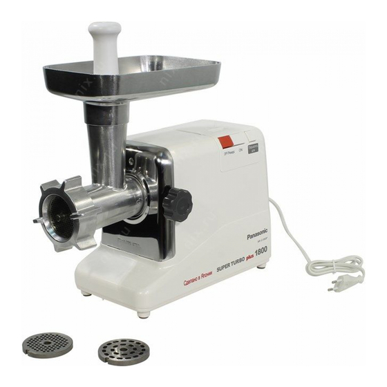
Meat Grinder
MKG1800PWTB
S.A
Specification
Rated voltage:
Power consumption:
Rated power frequency:
Feed screw speed
Motor protection:
Dimensions:
Weight:
Accessories:
© 2005 Matsushita Electric Industrial Co., Ltd. All rights reserved. Unauthorized copying and distribution is a violation of law.
file:///C:/Users/sh.dehghani/Desktop/1111111111111111111111111111111/viewing/SGML_VIEW_DATA/OT/MKG1800PWTB/SVC/KAD0509007CE/index.html
AC220240V
330W
5060Hz
240rpm
Circuit breaker
430(H) x 180(W) x 418(D)mm
Approx. 5.9kg
Coarse, Medium, Fine,
Grinding cutters
index.html
KAD0509007CE
1/1
Advertisement
Table of Contents

Related Manuals for Panasonic MK-G1800PWTQ


Summary of Contents for Panasonic MK-G1800PWTQ
- Page 1 9/29/2016 index.html KAD0509007CE Meat Grinder MKG1800PWTB Specification Rated voltage: AC220240V Power consumption: 330W Rated power frequency: 5060Hz Feed screw speed 240rpm Motor protection: Circuit breaker Dimensions: 430(H) x 180(W) x 418(D)mm Weight: Approx. 5.9kg Coarse, Medium, Fine, Accessories: Grinding cutters © 2005 Matsushita Electric Industrial Co., Ltd. All rights reserved. Unauthorized copying and distribution is a violation of law. file:///C:/Users/sh.dehghani/Desktop/1111111111111111111111111111111/viewing/SGML_VIEW_DATA/OT/MKG1800PWTB/SVC/KAD0509007CE/index.html...
-
Page 2: Schematic Diagram
9/29/2016 index.html 2 SCHEMATIC DIAGRAM file:///C:/Users/sh.dehghani/Desktop/1111111111111111111111111111111/viewing/SGML_VIEW_DATA/OT/MKG1800PWTB/SVC/KAD0509007CE/index.html... -
Page 3: Basic Wiring Diagram
9/29/2016 index.html 3 BASIC WIRING DIAGRAM file:///C:/Users/sh.dehghani/Desktop/1111111111111111111111111111111/viewing/SGML_VIEW_DATA/OT/MKG1800PWTB/SVC/KAD0509007CE/index.html... -
Page 4: Troubleshooting Guide
9/29/2016 index.html 4 TROUBLESHOOTING GUIDE 4.1 SYMPTOM : A.C. motor interrupted when feeding meat (overloaded). Causes Remedy Too hard meat being fed. Take out the hard meat. Too much meat being fed at once Reduce the meat feed rate. Used for too long continuously. Follow the specified operating time. Circuit breaker activated. Switch off and on again to reset the breaker. 4.2 SYMPTOM : Switch turned on, but A.C. motor failure to start. Causes Remedy Power cord broken. Replace the power cord. Lead wire terminal in poor contact. Repair or replace the lead wire terminal. Switch in poor contact. Replace the switch. Carbon brush worn out. Replace the carbon brush. A.C. motor coil broken. Replace the A.C. motor. 4.3 SYMPTOM : A.C. motor running, but feed screw failure to turn. Causes Remedy Gears worn out. Replace the gears. Gears damaged. Replace the gears. Feed screw worn out. Replace the feed screw. Feed screw damaged. Replace the feed screw. 4.4 SYMPTOM : A.C. motor running too noisy and meat grinding too slow. - Page 5 9/29/2016 index.html Causes Remedy Causes Remedy Foreign mater caught in gears. Take out the foreign matter. Gears worn out or damaged. Replace the gears. 4.6 SYMPTOM : Smell of burning from A.C. motor. Causes Remedy A.C. motor insulation degraded. Replace the A.C. motor. file:///C:/Users/sh.dehghani/Desktop/1111111111111111111111111111111/viewing/SGML_VIEW_DATA/OT/MKG1800PWTB/SVC/KAD0509007CE/index.html...
- Page 6 9/29/2016 index.html 5 DISASSEMBLY INSTRUCTIONS 5.1 Motor Housing, Bottom Plate and Cord Box ( Fig.1 , Fig.2 ) 1. Remove the loking knob for removal of the grinder head section. 2. Remove the set screws (7 pcs.) from the bottom plate for removal thereof. 3. Remove the cord box and cord box cover from the motor housing. 4. Remove the set screws (4 pcs.) from the gear case section and also the other set screws (2 pcs.) from the switch. Then, take out the gear case section, the motor assembly, the switch assembly and the cord from the motor housing. 5. Remove the switch cover from the motor housing by folding back the claw sections of switch cover, using a regular screwdriver. (See Fig. 2.) 6. Remove the housing cover from the motor housing. 5.2 Power Cord, Switch ( Fig.2 ) 1. Disconnect the connector C from the power cord. 2. Disconnect the connector B of the switch. Fig.2 Fig.1 5.3 Removing the Condenser unit ( Fig.3 ) 1. Disconnect the 2connectors from Motor’s terminal. 2. Remove the fixnut from the Motor. Fig.3 file:///C:/Users/sh.dehghani/Desktop/1111111111111111111111111111111/viewing/SGML_VIEW_DATA/OT/MKG1800PWTB/SVC/KAD0509007CE/index.html...
- Page 7 9/29/2016 index.html 5.4 Cooling Guide and Carbon Brush ( Fig.4 , Fig.5 ) 1. Remove the connector A from the motor. 2. Open the two claws of cooling guide. 3. Open the carbon holder using a () screwdriver as shown in the Figure 4. 4. There is a copper wire fixed to the shoulder of the carbon brush. Cut the copper wire using nippers, then pull out the carbon brush. (Figure 5). 5. Insert a new carbon brush into the carbon support plate, then close the carbon holder. Both the right and left carbon brushes should be replaced at the same time. Fig.4 Fig.5 5.5 Gear D Shaft, Gear D, Gera C, Gear A and Motor ( Fig.6 ) 1. Remove the gear case section and the motor assembly from the motor housing. 2. Removal of the set screws (3 pcs.) from the gear case cover will allow removal of the gear case cover section. (In this case the gear D shaft and the gear D remain assembled.) 3. Remove “C” type ring for removal of the gear D shaft and the gear D. 4. Since the gear C and the gear A are merely inserted in the gear case shaft, pull them out for replacement. 5. After the gears C and A are removed, remove the set screws (3 pcs.) of motor fastening the gear case, for replacement of the motor. Fig.6 file:///C:/Users/sh.dehghani/Desktop/1111111111111111111111111111111/viewing/SGML_VIEW_DATA/OT/MKG1800PWTB/SVC/KAD0509007CE/index.html...
- Page 8 9/29/2016 index.html 5.6 Sections to be Greasedup ( Fig.7 ) Apply grease to the following sections. engaged sections of each gear inner surface of gear case cover bearing inner surfaces of Gears A and C bearings shaft sections of Gears A and C Fig.7 file:///C:/Users/sh.dehghani/Desktop/1111111111111111111111111111111/viewing/SGML_VIEW_DATA/OT/MKG1800PWTB/SVC/KAD0509007CE/index.html...
- Page 9 9/29/2016 m12c3v01.png (526×679) file:///C:/Users/sh.dehghani/Desktop/1111111111111111111111111111111/viewing/SGML_VIEW_DATA/OT/MKG1800PWTB/SVC/KAD0509007CE/doc/m12c3v01.…...
-
Page 10: Replacement Parts List
9/29/2016 index.html This page contains the following errors: error on line 898 at column 10: Opening and ending tag mismatch: xref line 0 and html:p Below is a rendering of the page up to the first error. 7 REPLACEMENT PARTS LIST Important safety notice : Components identified by mark have special characteristics important for safety. When replacing any of these component, use only manufacturer´s specified part. Ref. No. Part No. Part Name & Description Remarks AMM23C300 Hopper plate AME04109W Food pusher AME99109 Grinder head AMM98C300 Feed screw AMM12C300 Cutting blade AME05109 Cutting plate Coarse 7.0mm AMM10C300 Cutting plate Fine 4.0mm AMM19C300 Cutting plate Medium 2.5mm AMM02C300 Grinder cap AMM12B300 Gear D shaft AMM36B090 Adjustment washer C AMM01Q300 Gear case cover AMM43B300 Felt... - Page 11 9/29/2016 index.html Ref. No. Part No. Part Name & Description Remarks AMU48A160 Adjustment washer B AMM04Q090 Gear C AMX25B310 Washer AMM02Q300 Gear case AMM29B410 Motor plate AMB92Y123W Switch cover AMA10J1152 Switch 220240V AMM36A410 Cooling guide SMS242T A.C. Motor 220240V AMM16F4302 Carbon brush 2pcs set AMA22J115 Connector A AMM12A300W Cord box cover AMM11A300W Cord box AMP91J115 Power cord S3P 220240V AMM98A300W Bottom plate W/Foot AMY10J123 Rating plate...
-
Page 12: Packing Instruction
9/29/2016 index.html 8 PACKING INSTRUCTION file:///C:/Users/sh.dehghani/Desktop/1111111111111111111111111111111/viewing/SGML_VIEW_DATA/OT/MKG1800PWTB/SVC/KAD0509007CE/index.html...