
Related Manuals for Motorola APX N50


Summary of Contents for Motorola APX N50
- Page 1 Two-Way Radios ™ Model 2 ™ N50 User Guide JUNE 2022 *MN009203A01* MN009203A01-AA © 2022 Motorola Solutions, Inc. All rights reserved...
-
Page 2: Table Of Contents
Notice to Users (FCC) ......................12 FCC Licensing Information....................13 Applying for Canadian License..................13 Limited Warranty..........................14 MOTOROLA SOLUTIONS COMMUNICATION PRODUCTS.......... 14 I. WHAT THIS WARRANTY COVERS AND FOR HOW LONG:........14 II. GENERAL PROVISIONS:.................... 15 III. STATE LAW RIGHTS:....................15 IV. - Page 3 MN009203A01-AA Contents Removing the Battery....................... 28 3.2 Attaching and Removing the Antenna................... 28 Attaching the Antenna.......................28 Removing the Antenna..................... 28 3.3 Attaching and Removing the Accessory Connector Cover............29 Attaching the Accessory Connector Cover............... 29 Removing the Accessory Connector Cover..............29 3.4 Attaching the Belt Clip......................
- Page 4 MN009203A01-AA Contents 5.17 General Radio Information....................43 5.17.1 Accessing the General Radio Information............. 43 Chapter 6: Trunking System Controls..............44 6.1 Operating in Failsoft System....................44 6.2 Out-of-Range Radio.......................44 6.3 Site Trunking Feature......................44 6.4 Locking or Unlocking Sites....................44 6.5 Viewing the Current Site......................45 6.6 Changing the Current Site.....................
- Page 5 MN009203A01-AA Contents 12.2.1 Multikey Feature....................58 12.2.2 MDC OTAR (Conventional Only)................59 12.2.3 Infinite UKEK Retention..................59 12.2.4 Hear Clear......................59 12.2.5 Loading Encryption Keys..................60 12.2.6 Selecting Encryption Keys..................60 12.2.7 Selecting Keysets....................60 12.2.8 Erasing Encryption Keys..................60 12.2.9 Requesting Over-the-Air Rekey................61 Chapter 13: Scan.....................62 13.1 Turning Scan On or Off......................62 13.2 Making Dynamic Priority Change (Conventional Scan Only)..........
- Page 6 MN009203A01-AA Contents 17.3 Exit from Mission Critical Geofence..................73 Chapter 18: Contacts....................74 18.1 Viewing Contact Details.......................74 Chapter 19: Recent Calls..................75 19.1 Viewing Recent Calls......................75 Chapter 20: Sending Status................... 76 Chapter 21: Call Alert Paging.................77 21.1 Sending Call Alert Page.......................77 21.2 Receiving Call Alert Page....................78 Chapter 22: Automatic Registration Service............
- Page 7 MN009203A01-AA Contents Chapter 33: Voice Announcement.................94 Chapter 34: Site Selectable Alerts.................95 34.1 Sending Site Selectable Alert Notification................95 34.2 Stopping Site Selectable Alert Notification................95 Chapter 35: Additional Performance Enhancement..........97 35.1 ASTRO 25 Enhanced Data....................97 35.2 Dynamic System Resilience....................97 35.3 Encrypted Integrated Data....................97 35.4 SecureNet..........................97 35.5 P25 Digital Vehicular Repeater System................97...
-
Page 8: List Of Figures
MN009203A01-AA List of Figures List of Figures Figure 1: Radio Overview ........................20 Figure 2: Keypad Overview ........................21 Figure 3: Home Screen Display ......................31... - Page 9 MN009203A01-AA List of Tables List of Tables Table 1: Radio Overview Description ....................20 Table 2: Keypad Overview ........................22 Table 3: Assignable Radio Functions ....................22 Table 4: ViQi Basic Voice Control Commands ..................25 Table 5: ViQi Virtual Partner Queries ....................26 Table 6: Home Screen Overview Description ..................31 Table 7: Status Icons ..........................32 Table 8: LED Indications ........................
-
Page 10: Legal And Support
License Rights The purchase of Motorola Solutions products shall not be deemed to grant either directly or by implication, estoppel or otherwise, any license under the copyrights, patents or patent applications of Motorola Solutions, except for the normal non-exclusive, royalty-free license to use that arises by operation of law in the sale of a product. -
Page 11: Legal And Compliance Statements
Furthermore, Motorola Solutions reserves the right to change any products to improve readability, function, or design. Motorola Solutions does not assume any liability arising out of the applications or use of any product or circuit described herein; nor does it cover any license under its patent rights, nor the rights of others. -
Page 12: Industry Canada Wlan Statement
Before using the radio, read the RF Energy Exposure and Product Safety Guide for Portable Two-Way Radios which contains important operating instructions for safe usage and RF energy awareness and control for Compliance with applicable standards and Regulations. For a list of Motorola Solutions-approved antennas, batteries, and other accessories, visit the following website:... -
Page 13: Notice To Users (Fcc)
(e.i.r.p.) is not more than that necessary for successful communication. This radio transmitter is approved by Industry Canada to operate with a Motorola Solutions-approved antenna with the maximum permissible gain and required antenna impedance for each antenna type indicated. - Page 14 Legal and Support Applying for Canadian License The operation of your Motorola Solutions radio is subject to the Radio communications Act and must comply with rules and regulations of the Federal Government's department of Industry Canada. Industry Canada requires that all operators using Private Land Mobile frequencies obtain a radio license before operating their equipment.
- Page 15 Adresse : 2000 Progress Pkwy, Schaumburg, IL 60196-1078, États-Unis Numéro de téléphone : 1 800 927-2744 Par les présentes, il est déclaré que la radio APX N50 est conforme aux normes de la FCC, Partie 15, Sous-partie B, section 15.107(a) et 15.107(d), et section 15.109(a) Appareil numérique de classe B...
- Page 16 MN009013A01-AA Avis juridique et soutien 2 Cet appareil doit accepter toute interférence reçue, y compris les interférences pouvant entraîner un fonctionnement indésirable. REMARQUE : Cet équipement a fait l’objet de tests et a été déclaré conforme aux limites établies pour un appareil numérique de classe B, conformément à la section 15 des règlements de la FCC.
- Page 17 Cet émetteur radio a été approuvé par Industrie Canada pour utilisation avec une antenne approuvée par Motorola Solutions offrant le gain maximal autorisé et l’impédance requise pour le type d’antenne indiqué. Il est strictement interdit d’utiliser avec cet appareil tout type d’antenne ne figurant pas dans cette liste et présentant un gain supérieur au maximum indiqué...
- Page 18 Pour toute question sur le choix de la fréquence radio, appelez les services sur les produits de Motorola Solutions au numéro suivant : 1 800 448-6686. Toute modification apportée à cet appareil sans l’autorisation explicite de Motorola peut annuler l’autorisation d’utiliser cet appareil, telle qu’émise par la FCC, et ne devrait pas être faite.
-
Page 19: Applying For Canadian License
MN009013A01-AA Déclarations juridiques et de conformité 2 Faites une copie de vos fichiers. 3 Préparez un chèque ou un mandat à l’ordre du « Receveur général du Canada », d’un montant correspondant à chaque radio achetée. La licence est renouvelée le 1er avril de chaque année et est émise pour une période de 12 mois. -
Page 20: Limited Warranty
Product Accessories One (1) Year MOTOROLA SOLUTIONS, at its option, will at no charge either repair the Product (with new or reconditioned parts), replace it (with a new or reconditioned Product), or refund the purchase price of the Product during the warranty period provided it is returned in accordance with the terms of this warranty. -
Page 21: Ii. General Provisions
Warranty service will be provided by MOTOROLA SOLUTIONS through one of its authorized warranty service locations. If you first contact the company which sold you the Product (e.g., dealer or communication service provider), it can facilitate your obtaining warranty service. -
Page 22: Vi. Patent And Software Provisions
1 that MOTOROLA SOLUTIONS will be notified promptly in writing by such purchaser of any notice of such claim,... -
Page 23: Read Me First
MN009363A01-AA Read Me First Read Me First This User Guide covers the basic operation of the radio. Notations Used in This Manual Notations such as Warning, Caution, and Notice are used throughout the text in this publication. These notations are used to emphasize that safety hazards exist, and the care that must be taken or observed. -
Page 24: Chapter 1: Radio Care
MN009203A01-AA Chapter 1 : Radio Care Chapter 1 Radio Care Proper radio usage and care ensure efficient operation and long life of the product. CAUTION: Use the radio according to the following recommendations and warnings. • Never obstruct or cover the vent port, even with a label. •... -
Page 25: Radio Service And Repair
Radio Service and Repair Proper repair and maintenance procedures ensure efficient operation and long life of this radio. A Motorola Solutions maintenance agreement provides expert service to keep the radio and all other communication equipment in perfect operating condition. A nationwide service organization is provided by Motorola Solutions to support maintenance services. -
Page 26: Chapter 2: Radio Overview
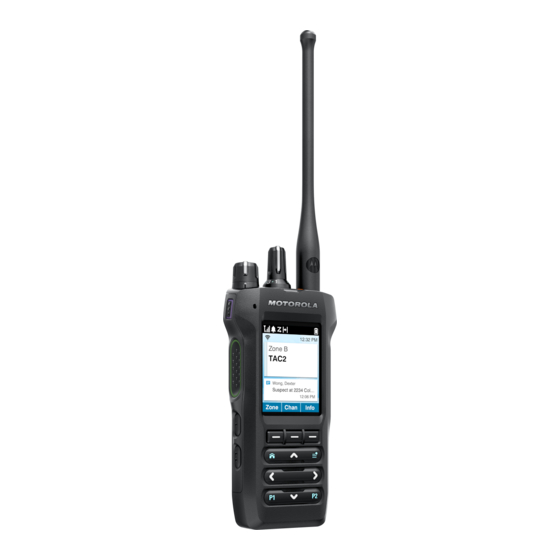
MN009203A01-AA Chapter 2 : Radio Overview Chapter 2 Radio Overview Figure 1: Radio Overview Table 1: Radio Overview Description Number Button Name Description Antenna Provides the required RF amplification when transmitting or receiving. Channel Selector knob Allows you to select channel. On/Off/Volume Control knob Allows you to turn on or off the radio, and adjust the volume. -
Page 27: Keypad Overview
MN009203A01-AA Chapter 2 : Radio Overview Number Button Name Description Speaker Outputs tones and audio that are generated by the radio. Menu Navigation buttons Allows menu navigation and interface selection. Display The radio display screen. Digital Mic 2 Allows your voice to be sent when PTT or voice operations are activated. -
Page 28: Programmable Radio Functions
MN009203A01-AA Chapter 2 : Radio Overview Table 2: Keypad Overview Number Button Name Description Menu Select buttons Press to access the corresponding menu. Home button Press to return to Home screen. Programmable button 1 (P1) This button is field programmable using the Customer Programming Software (CPS). - Page 29 MN009203A01-AA Chapter 2 : Radio Overview Function Description Channel Announcement Allows you to hear the Voice Announcement audio file that is assigned to the radio's current channel/mode. Channel Up/Down Allows you to scroll up or down to other channels within the current Zone.
- Page 30 MN009203A01-AA Chapter 2 : Radio Overview Function Description Phone Allows you to make and receive calls similar to standard phone calls. Private Call (Trunking Only) Allows you to dial the programmed ID (number) and initiate the Private Call. Private Line Disable (Conventional Allows you to adjust squelch level of the radio between level Only) 0 and 15 when you press and hold the button.
-
Page 31: Viqi
MN009203A01-AA Chapter 2 : Radio Overview Function Description TMS Query Launches a list of predefined short text messages only after logging in with Two-Factor Authentication. TMS Quick Text Selects a predefined message. Transmit Power Level Toggles between the power levels at which your radio trans- mits. -
Page 32: Table 5: Viqi Virtual Partner Queries
MN009203A01-AA Chapter 2 : Radio Overview Feature Examples • <Volume Medium> – 50% • <Volume High> – 100% Zone To identify your current zone, say the following command: • "Zone" ViQi Virtual Partner To initiate ViQi Virtual Partner, say the following command: •... -
Page 33: Activating Basic Voice Control
MN009203A01-AA Chapter 2 : Radio Overview Query Examples "Am I still at the <Location>?" NOTE: ViQi will ask for more information to complete the query. Target Location "Where is <Unit Name>? "Tell me where <Unit Name> is. NOTE: ViQi will ask for more information to complete the query. You are also able to receive and listen to LMR and Virtual Partner over broadband audio simultaneously. -
Page 34: Chapter 3: Getting Started
MN009203A01-AA Chapter 3 : Getting Started Chapter 3 Getting Started This section provides instructions to prepare your radio for use. Attaching and Removing the Battery Attaching the Battery Procedure: Slide the battery into the radio frame until the latches click into place. Removing the Battery Procedure: 1 Turn off the radio. -
Page 35: Attaching And Removing The Accessory Connector Cover
Do not discard batteries in a fire. When and where to use: Motorola Solutions-approved battery shipped with your radio is uncharged. Prior to using a new battery, charge it for a minimum of 16 hours to ensure optimum capacity and performance. -
Page 36: Turning The Radio On Or Off
MN009203A01-AA Chapter 3 : Getting Started 2 Place the radio in a Motorola Solutions-approved charger. The LED on the charger indicates the charging progress. For more information, see the Charger User Guide. Turning the Radio On or Off Prerequisites: Ensure that the battery is fully charged before the first use. -
Page 37: Chapter 4: Home Screen Overview
MN009203A01-AA Home Screen Overview Chapter 4 Home Screen Overview Figure 3: Home Screen Display Table 6: Home Screen Overview Description Number Name Description Dark Mode Status Bar Dark mode status icons appear in the status bar to provide device status and feature notifi- cations. -
Page 38: Status Indicators
MN009203A01-AA Chapter 4 : Home Screen Overview Status Indicators This section explains the status indicators of the radio. 4.1.1 Status Icons These icons appear at the status bar to provide device-specific information or status. Table 7: Status Icons Icon Name Description Battery Level Indicates the remaining battery level of the ra-... - Page 39 MN009203A01-AA Chapter 4 : Home Screen Overview Icon Name Description Bluetooth Connectivity Steady Bluetooth is connected to the external Blue- tooth device. Blinking The Bluetooth device is disconnected. Call Received The radio received a call. Direct Mode The radio is configured for direct radio-to-radio communication in conventional operation.
- Page 40 MN009203A01-AA Chapter 4 : Home Screen Overview Icon Name Description Satellite Network is Active Steady The satellite system is available and con- nected. Blinking The ARS user login failed while in the satel- lite system. Satellite Receiving The radio is receiving a satellite signal. Satellite Transmitting The radio is transmitting a satellite signal.
-
Page 41: Led Indications
MN009203A01-AA Chapter 4 : Home Screen Overview Icon Name Description Blinking The radio is receiving an encrypted voice call. Advanced Encryption Stand- Steady ard (AES) Secure Operation The radio is operating in an AES-secure channel. Blinking The radio is receiving an AES-encrypted voice call. -
Page 42: Intelligent Lighting Indicators
MN009203A01-AA Chapter 4 : Home Screen Overview 4.1.3 Intelligent Lighting Indicators This feature temporarily changes the color of the Top Lightbar and adds a color bar to the main display screen to help signal that a radio event has occurred. Table 9: Intelligent Lighting Indicators Backlight and Bar Notification... - Page 43 MN009203A01-AA Chapter 4 : Home Screen Overview Indicator Lightbar Color Call State Voice Transmission Light Blue Out of Range Light Blue Smart Connect Gray Unprogrammed Gray Receiving Frequency Error...
-
Page 44: Chapter 5: General Radio Operation
MN009203A01-AA Chapter 5 : General Radio Operation Chapter 5 General Radio Operation This chapter explains the general operations of your radio. Selecting Zones A zone is a group of channels. Procedure: 1 Press the Zone menu item. 2 Select the required zone and press Sel. Selecting Channels A channel is a group of radio characteristics, such as transmit or receive frequency pairs. -
Page 45: Saving Zones And Channels
MN009203A01-AA Chapter 5 : General Radio Operation 5.3.1 Saving Zones and Channels You can save frequently used zones and channels to the programmable buttons. Procedure: 1 Toggle from your current zone and channel to the required zone and channel. 2 To save zones and channels to a button, press and hold the button you want to program. If the zone and channel is saved, a tone sounds. -
Page 46: Adjusting The Display Backlight
MN009203A01-AA Chapter 5 : General Radio Operation Adjusting the Display Backlight You can enable or disable the radio display backlight as needed, if poor light conditions make the display or keypad difficult to read. NOTE: The backlight setting also affects the Menu Select buttons and Navigation button backlighting accordingly. -
Page 47: Setting The Voice Mute
MN009203A01-AA Chapter 5 : General Radio Operation 5.11 Setting the Voice Mute This feature allows you to mute the voice transmission of the current zone and channel. Procedure: Turn Voice Mute on or off by pressing the VMut menu item. If Voice Mute is successfully turned on, your radio shows the following indications: •... -
Page 48: Conventional Squelch Operation
MN009203A01-AA Chapter 5 : General Radio Operation 5.14 Conventional Squelch Operation This feature filters out unwanted calls with low signal strength or channels that have a higher than normal background noise. Analog Options Tone Private Line, Digital Private-Line, and carrier squelch is available (preprogrammed) per channel. Option Result Carrier squelch... -
Page 49: Digital Ptt Id Support
MN009203A01-AA Chapter 5 : General Radio Operation 5.16 Digital PTT ID Support This feature allows you to see the radio ID (number) of the radio from whom you are currently receiving a transmission. The receiving radio and the dispatcher can view the ID, which consists of up to a maximum of eight characters. -
Page 50: Chapter 6: Trunking System Controls
MN009203A01-AA Chapter 6 : Trunking System Controls Chapter 6 Trunking System Controls This chapter explains the trunking system control features on your radio. Operating in Failsoft System The failsoft system ensures continuous radio communication during a trunked system failure. If a trunking system fails completely, the radio goes into failsoft operation and automatically switches to its failsoft channel. -
Page 51: Viewing The Current Site
MN009203A01-AA Chapter 6 : Trunking System Controls Viewing the Current Site Procedure: Press the programmed Site Displ/Srch button. The display shows the name of the current site and corresponding received RSSI. Changing the Current Site Procedure: Press and hold the programmed Site Displ/Srch button. The radio shows the following indications: •... -
Page 52: Chapter 7: Types Of Radio Calls
MN009203A01-AA Chapter 7 : Types of Radio Calls Chapter 7 Types of Radio Calls Your radio can make a Talkgroup, Private, Selective, Status, and Telephone call in conventional and/or trunking mode. Call Type Conventional Trunking SmartConnect Mode Mode Talkgroup Call This feature is a point-to-multipoint call operation. -
Page 53: Receiving Calls
MN009203A01-AA Chapter 7 : Types of Radio Calls Option Actions Private Call a Enter the Contacts page by pressing the Cnts menu item. b Select the required preprogrammed contact. c Start the call by pressing the PTT button. d To end the call, press Exit. Selective Call a Enter the Contacts page by pressing the Cnts menu item. -
Page 54: Making Priority Dispatch Calls
MN009203A01-AA Chapter 7 : Types of Radio Calls Option Actions c To listen, release the PTT button. d To end the call, press End. Selective Call For incoming Selective Calls, your radio automatically plays the transmission from the call. a Respond to the call by pressing and holding the PTT button. -
Page 55: Chapter 8: Emergency Operation
MN009203A01-AA Emergency Operation Chapter 8 Emergency Operation The Emergency feature is used to indicate a critical situation. An emergency signal overrides any other communication over the selected channel. Your radio supports the following Emergency modes: • Emergency Alarm • Emergency Call •... -
Page 56: Sending Emergency Alarms
MN009203A01-AA Chapter 8 : Emergency Operation Sending Emergency Alarms Procedure: Press the programmed Top (Orange) button. Your radio shows the following indications: • A positive indicator tone sounds. • The red LED blinks. • The display shows Emergency, and the current zone or channel. When you receive acknowledgement from the dispatcher, your radio shows the following indications: •... -
Page 57: Emergency Keep-Alive
MN009203A01-AA Chapter 8 : Emergency Operation Option Actions Exiting Emergency operation initiated by a Press and hold the 1-Dot Programma- other radios ble button. b Press the Top (Orange) button. Exiting Emergency operation initiated by Perform one of the following actions: the Supervisor Press and hold the Top (Orange) button. -
Page 58: Receiving Emergency Beacons
MN009203A01-AA Chapter 8 : Emergency Operation 8.6.2 Receiving Emergency Beacons When you receive emergency beacon, the display shows Beacon Received, the transmitting radio ID, or alias. Procedure: 1 Perform one of the following actions: • To view the beacon list, press Details. •... -
Page 59: Chapter 9: Fireground
MN009203A01-AA Fireground Chapter 9 Fireground The portable Fireground Communications System is designed for deployment at an incident scene. It consists of central components that provide on-scene and in building radio coverage, and enhanced personnel accountability and monitoring: • Your APX portable radios •... -
Page 60: Sending Evacuation Tone
MN009203A01-AA Chapter 9 : Fireground • A tone sounds. • The display shows the configurable programmed alert text and intelligent lighting. Procedure: 1 To respond, perform one of the following actions: • Press the 3-Dot Programmable button. • If the radio is connected to the Remote Speaker Microphone (RSM), press the 1-Dot button on the RSM. -
Page 61: Chapter 10: Tactical Public Safety (Conventional Only)
MN009203A01-AA Tactical Public Safety (Conventional Only) Chapter 10 Tactical Public Safety (Conventional Only) Tactical Public Safety (TPS) enables the member of a group to identify the start and the end of a transmission by displaying the caller name or ID on the radio display. 10.1 Using TPS Normal Transmission Procedure:... -
Page 62: Chapter 11: Man Down (Fall Alert)
MN009203A01-AA Chapter 11 : Man Down (Fall Alert) Chapter 11 Man Down (Fall Alert) Man Down (Fall Alert) is a supporting feature of the Emergency operation. The Emergency feature must be programmed for Man Down (Fall Alert) to operate. Your radio activates the Man Down (Fall Alert) feature when it achieves or exceeds a tilt angle threshold or a combination of the angle threshold and radio motion below the motion sensitivity level. -
Page 63: Exiting Man Down (Fall Alert)
MN009203A01-AA Chapter 11 : Man Down (Fall Alert) Procedure: 1 Turn on the radio, and place it in a vertical position for at least 5 seconds. 2 Lay the radio down in a horizontal position. Your radio shows the following indications: •... -
Page 64: Chapter 12: Secure Operations
MN009203A01-AA Chapter 12 : Secure Operations Chapter 12 Secure Operations Secure radio operation provides the highest commercially available level of voice security on both trunked and conventional channels. By default, the radio automatically enters the encrypted environment without having to manually select or clear the secure transmission. -
Page 65: Mdc Otar (Conventional Only)
12.2.2 MDC OTAR (Conventional Only) This feature allows you to view or define the Motorola Data Communications (MDC) Over-the- Air Rekeying (OTAR) features. It is applied only when operating in secure encrypted mode. In addition to Rekey Requests, OTAR transmissions include Delayed Acknowledgments, and Power-up Acknowledgments. -
Page 66: Loading Encryption Keys
MN009203A01-AA Chapter 12 : Secure Operations 12.2.5 Loading Encryption Keys Procedure: 1 Attach the Key Variable Loader (KVL) to your radio. The display shows Keyloading. All other radio functions are locked, except power down, backlight, and volume. NOTE: If the Multisystem Over-the-Air Rekeying feature is in use, the ASTRO profile name is displayed below Keyloading. -
Page 67: Requesting Over-The-Air Rekey
MN009203A01-AA Chapter 12 : Secure Operations 12.2.9 Requesting Over-the-Air Rekey If the Multi-system Over-the-Air Rekeying feature is in use, the rekey request is only for the current selected secure profile. Prerequisites: Ensure that the Unique Key Encryption Key (UKEK) or Unique Shadow Key (USK) is loaded into the radio with the Key Variable Loader (KVL) before the rekey request can be sent. -
Page 68: Chapter 13: Scan
MN009203A01-AA Chapter 13 : Scan Chapter 13 Scan This feature allows you to monitor traffic on different channels by scanning a programmed list of channels. Scanning is halted if you initiate a call and resumes when the call has ended. 13.1 Turning Scan On or Off Procedure:... - Page 69 MN009203A01-AA Chapter 13 : Scan • Cycle power your radio.
-
Page 70: Chapter 14: Scan Lists
MN009203A01-AA Chapter 14 : Scan Lists Chapter 14 Scan Lists Scan lists are created and assigned to individual channels/groups. Your radio scans for voice activity by cycling through the channel/group. The sequence of scan is as specified in the scan list for the current channel/group. -
Page 71: Chapter 15: Connectivity
Bluetooth ® This feature allows your radio to extend its functionality by connecting to external proprietary Motorola Solutions accessories. Use Motorola Solutions proprietary Mission Critical Wireless (MCW) devices with APX radios during Mission Critical operations. Other Bluetooth devices may or may not meet the mission critical standard. -
Page 72: Turning Bluetooth On Or Off
MN009203A01-AA Chapter 15 : Connectivity 15.3.1 Turning Bluetooth On or Off Procedure: 1 Press the BT menu item. 2 Press Status. 3 Perform one of the following actions: • To turn on Bluetooth, press On. • To turn off Bluetooth, press Off. 15.3.2 Searching and Pairing the Bluetooth Device Prerequisites: Ensure that the Bluetooth on your device is turned on and set to Discoverable in order... -
Page 73: Astro 25 (P25) Programming Over Project 25 (Pop25)
MN009203A01-AA Chapter 15 : Connectivity 4 To clear a device from the list, select the required device and press Clr→Yes. The display shows that the device is cleared. 15.4 ASTRO 25 (P25) Programming Over Project 25 (POP25) Also called Over-the-Air Programming, this feature allows configuration data and firmware to be upgraded to your radio over-the-air. -
Page 74: Chapter 16: Location
MN009203A01-AA Chapter 16 : Location Chapter 16 Location The Global Navigation Satellite System (GNSS) in the radio integrates information from the Global Positioning System (GPS) to determine the approximate geographical location of your radio. NOTE: The Location feature is addressed as GPS across the manual as the naming convention of the buttons and strings remain the same as the legacy feature of GPS. -
Page 75: Selecting Location Formats
MN009203A01-AA Chapter 16 : Location • Press Optn→Turn On GPS→Sel. • If preprogrammed by your system administrator, press On. The radio displays the following information of the previous location: • Military Grid Reference System (MGRS), or latitude and longitude location •... -
Page 76: Managing Waypoints
MN009203A01-AA Chapter 16 : Location 16.4 Managing Waypoints Prerequisites: Ensure that your radio displays the current location. Procedure: 1 Press the Optn menu item. 2 Press Waypoints→Sel. 3 Manage waypoints by using the following options: Option Actions Viewing waypoints a Scroll to the required waypoint from the list. b Press Optn→View→Sel. -
Page 77: Peer-Location On The Display (Astro Conventional)
MN009203A01-AA Chapter 16 : Location 16.6 Peer-Location on the Display (ASTRO Conventional) This feature is only available for radio-to-radio voice transmissions, dispatch call, and selective call. The transmitting radio and receiving radio must be configured to enable the sending and receiving of the GPS coordinates. -
Page 78: Chapter 17: Mission Critical Geofence (Astro 25 Trunking)
MN009203A01-AA Chapter 17 : Mission Critical Geofence (ASTRO 25 Trunking) Chapter 17 Mission Critical Geofence (ASTRO 25 Trunking) This feature allows the radio to use the Global Positioning System (GPS) receiver to determine its location at frequent intervals and evaluate if the radio is within the Geofence area in real time. Geofence is a virtual perimeter based on the GPS to define a geographical area on earth. -
Page 79: Entry To Mission Critical Geofence
MN009203A01-AA Chapter 17 : Mission Critical Geofence (ASTRO 25 Trunking) The system sends a message to your radio. The radio display shows a direct text message content without any user operation. This message indicates that you are currently present in a Geofence area. This TMS remains open on the display until you press exit/home to exit this screen. -
Page 80: Chapter 18: Contacts
MN009203A01-AA Chapter 18 : Contacts Chapter 18 Contacts This feature provides “address-book” capabilities on your radio. Each entry corresponds to an alias (name) and ID (number) that you use to initiate a call. Contact entries are alphabetically sorted according to the entry alias. Each entry, depending on context (conventional, trunking, or phone), associates with one to five IDs according to the following types of calls: •... -
Page 81: Chapter 19: Recent Calls
MN009203A01-AA Recent Calls Chapter 19 Recent Calls Recent call menu allows you to view the recent incoming and outgoing call information. You can view the information of the following type of calls: • Call Alert • Selective Call • Private Call •... -
Page 82: Chapter 20: Sending Status
MN009203A01-AA Chapter 20 : Sending Status Chapter 20 Sending Status You can send status messages to the dispatcher. A status transmission makes more efficient use of a channel as compared to a voice transmission. Procedure: 1 Press the programmed Status button. 2 Select the required status. -
Page 83: Chapter 21: Call Alert Paging
MN009203A01-AA Call Alert Paging Chapter 21 Call Alert Paging This feature allows your radio to work like a pager. If other users are away from their radios or if they are unable to hear their radios, you can send them an individual call alert page. -
Page 84: Receiving Call Alert Page
MN009203A01-AA Chapter 21 : Call Alert Paging 21.2 Receiving Call Alert Page When you receive a Call Alert page, your radio shows the following indications: • A tone sounds. • The green LED illuminates. • The display shows Page received. Procedure: Press any button to clear the Call Alert page. -
Page 85: Chapter 22: Automatic Registration Service
MN009203A01-AA Automatic Registration Service Chapter 22 Automatic Registration Service Automatic Registration Service (ARS) provides an automated data application registration for your radio. When you turn on the radio, the device automatically registers with the server. Data applications within the fixed network determine the presence of a device on the system and send data to the device. -
Page 86: Chapter 23: User Login Feature
MN009203A01-AA Chapter 23 : User Login Feature Chapter 23 User Login Feature This feature allows you to take on a friendly username such as Text Messaging Service (TMS). You can still send text messages without logging in as a user. The user login feature only enables the recipient of your message to identify you as the sender by assigning a username to your message. - Page 87 MN009203A01-AA Chapter 23 : User Login Feature 2 Perform one of the following actions: • To clear all your private data, select Yes. • To keep your private data, select No.
-
Page 88: Chapter 24: Text Messaging Service
MN009203A01-AA Chapter 24 : Text Messaging Service Chapter 24 Text Messaging Service Text Messaging Service (TMS) allows you to send and receive messages and run database queries directly from your radios. The maximum number of characters allowed for a text message is 200 characters. -
Page 89: Accessing Messages
MN009203A01-AA Chapter 24 : Text Messaging Service Icon Name Description Message Sent The text message is sent. Message Unsent The text message cannot be sent. 24.2 Accessing Messages Quick Text messages are messages that are predefined and usually consist of messages that are used most frequently. -
Page 90: Chapter 25: Monitor Feature
MN009203A01-AA Chapter 25 : Monitor Feature Chapter 25 Monitor Feature The monitor feature ensures that a channel is clear before transmitting. The lack of static on a digital channel when the users switch from analog to digital radios is not an indication that the radio is malfunctioning. - Page 91 MN009203A01-AA Chapter 25 : Monitor Feature 3 To return to the original squelch setting, press the Monitor button again or the PTT button. If you try to transmit on a receive-only channel, you hear an invalid tone until you release the PTT button.
-
Page 92: Chapter 26: Remote Monitor
MN009203A01-AA Chapter 26 : Remote Monitor Chapter 26 Remote Monitor This feature allows the system administrator to turn on the microphone of a targeted radio with a subscriber alias or ID. When remote monitor feature is activated, the audio transmission can be configured in Customer Programming Software (CPS) to route the audio to the radio internal microphone, wired Remote Speaker Microphone (RSM), or Bluetooth wireless microphone. -
Page 93: Chapter 27: Transmit Inhibit
MN009203A01-AA Transmit Inhibit Chapter 27 Transmit Inhibit The Transmit Inhibit feature allows you to stop all transmission including voice and data. The radio can receive messages but not able to reply the acknowledgment request of the received message. This feature is available for APCO 25 Trunking, Type II Trunking and Conventional operations for all APX radios. - Page 94 MN009203A01-AA Chapter 27 : Transmit Inhibit Mode Description Quick-Key Override Your radio must be preprogrammed to allow you to use Quick-Key Override. This feature works with either one of the two above varia- tions. You can override the transmit-inhibit state by quick-keying the radio (press PTT button twice within the preprogrammed time limit).
-
Page 95: Chapter 28: Dynamic Regrouping (Trunking Only)
MN009203A01-AA Dynamic Regrouping (Trunking Only) Chapter 28 Dynamic Regrouping (Trunking Only) This feature allows the dispatcher to temporarily reassign selected radios to a particular channel to communicate with each other. When your radio is dynamically regrouped, it receives a dynamic regrouping command and automatically switches to the dynamically regrouped channel. -
Page 96: Chapter 29: Dynamic Zone Programming
MN009203A01-AA Chapter 29 : Dynamic Zone Programming Chapter 29 Dynamic Zone Programming Dynamic Zone Programming (DZP) provides one or more Dynamic Zones to store frequently used channels for conventional or trunking. NOTE: Your radio must be preprogrammed for you to use this feature. At least one zone in the radio must be a non-dynamic zone. -
Page 97: Chapter 30: Zone-To-Zone Cloning
MN009203A01-AA Zone-to-Zone Cloning Chapter 30 Zone-to-Zone Cloning Zone Cloning clones conventional zones from one radio to another. You can select the followings zones from a source radio and clone them into a target radio. • Clone enabled zones • Dynamic Zones •... -
Page 98: Chapter 31: Radio Kill
MN009203A01-AA Chapter 31 : Radio Kill Chapter 31 Radio Kill This feature allows you to render your radio or another radio inoperable if the radio is misplaced or lost. When a radio is killed, the display turns blank and all functions of the radio are not usable. The killed radio can only be recovered with a special device. -
Page 99: Chapter 32: Radio Inhibit
MN009203A01-AA Radio Inhibit Chapter 32 Radio Inhibit This feature allows the system administrator to put a radio into a nonfunctional state when the radio is missing or in an unknown hand. The radio stays in this state regardless of its power changes. NOTE: If the radio has Intersystem roaming capability, the system administrator is able to put the radio into a nonfunctional state when the missing radio roams to another system. -
Page 100: Chapter 33: Voice Announcement
MN009203A01-AA Chapter 33 : Voice Announcement Chapter 33 Voice Announcement This feature enables the radio to audibly indicate the current feature mode, zone, or channel assigned to the user. The available voice announcement (VA) priority options are: High Voice announcement is enabled even when the radio is receiving calls. Voice announcement is disabled when the radio is receiving calls. -
Page 101: Chapter 34: Site Selectable Alerts
MN009203A01-AA Site Selectable Alerts Chapter 34 Site Selectable Alerts A Site Selectable Alert (SSA) is an Intelligent Lighting indicator with audio alert. The alert is sent to radios at sites to notify the users when special situations occur. Your radio supports up to 250 site aliases. Only authorized radios are enabled to send SSA. NOTE: The alert alias, alert tone, and alert period are configured in the Customer Programming Software. - Page 102 MN009203A01-AA Chapter 34 : Site Selectable Alerts • To stop alert notifications of all sites, select [All Sites]. • To stop alert notifications of all available sites, select [All Avail]. 4 Press Send. 5 To return to the Home screen, press Exit. The display shows Sending req.
-
Page 103: Chapter 35: Additional Performance Enhancement
Communication (MDC) channel. 35.5 P25 Digital Vehicular Repeater System Motorola Solutions offers an MSI Certified APX compatible, third party, P25 Digital Vehicular Repeater System (DVRS). This provides low-cost portable radio coverage in areas where only mobile radio coverage is available. -
Page 104: Chapter 36: Accessories
Description PMNN4813_ Lithium-ion Battery, IMPRES 2 IP68 2850T Table 13: Belt Clip or Carry Solutions Part Number Description PMLN8369_ Belt Clip, APX N30/APX N50 2.0" PMLN8370_ Belt Clip, APX N30/APX N50 2.5" Table 14: Charger Part Number Description PMPN4593_ Multi-unit charger, IMPRES 2 6 Display Base PS000242A01 Power Supply Adaptor, Power Supply Brick 100 –... - Page 105 Chapter 8 : Accessories Part Number Description RLN6512_ EP7-M Sonic Defender, use with PMMN4096 RLN6513_ EP7-LG Sonic Defender, use with PMMN4096 5080384F72_ Replacement Foam Plugs for RLN6242. Noise reduction = 25dB. (Pack of 50 pairs) Table 16: Microphone Part Number Description NMN6271_ IMPRES XP Remote Speaker Microphone with Dual Mic Noise...
- Page 106 Chapter 8 : Accessories Table 20: Surveillance Kit Part Number Description PMLN8295_ RM760 Replacement Cable PMLN8337_ 1-Wire single earbud with removable earhook loud audio ear- piece PMLN8341_ Audio Accessory-earpiece, 1-Wire XLClear Tube Earpiece PMLN8342_ Audio Accessory-earpiece, 2-Wire XLClear Tube Earpiece PMLN8343_ Audio Accessory-earpiece, 3-Wire XLClear Tube Earpiece RLN6282_...