Motorola APX 6000 User Manual
Model 2
Hide thumbs
Also See for APX 6000:
- User manual (174 pages) ,
- User manual (110 pages) ,
- User manual (160 pages)
Table of Contents
Advertisement
Quick Links
Download this manual
See also:
User Manual
Advertisement
Table of Contents

Related Manuals for Motorola APX 6000


Summary of Contents for Motorola APX 6000
- Page 1 TWO-WAY RADIOS APX 6000 / APX 6000Li MODEL 2 USER GUIDE...
- Page 3 PMLN5716D MOTOROLA, MOTO, MOTOROLA SOLUTIONS and the Stylized M logo are trademarks or registered trademarks of Motorola Trademark Holdings, LLC and are used under license. All other trademarks are the property of their respective owners. © 2011–2012 by Motorola Solutions, Inc. All Rights Reserved. 10/12 English 1303 East Algonquin Road, Schaumburg,Illinois 60196, U.S.A.
-
Page 4: Display Status Icons
On = Secure operation. Sending an Emergency Call Blinks when the battery is low. Off = Clear operation. Press the Emergency button. The more stripes, the stronger the Blinking = Receiving an encrypted signal strength for the current site voice call. Press and hold the PTT button. -
Page 5: Declaration Of Conformity
Address: 1303 East Algonquin Road, Schaumburg, Illinois 60196, U.S.A. Phone Number: 1-800-927-2744 Hereby declares that the product: Model Name: APX 6000/APX 6000Li conforms to the following regulations: FCC Part 15, subpart B, section 15.107(a), 15.107(d) and section 15.109(a) Class B Digital Device As a personal computer peripheral, this device complies with Part 15 of the FCC Rules. - Page 6 Note: This equipment has been tested and found to comply with the limits for a Class B digital device, pursuant to part 15 of the FCC Rules. These limits are designed to provide reasonable protection against harmful interference in a residential installation.
-
Page 7: Table Of Contents
Documentation Copyrights ....xii Contents Disclaimer ......xii This User Guide contains all the information you need to use the APX™... - Page 8 Adjusting the Volume ......8 Phone Call Display and Alert Prompts ..28 Identifying Radio Controls .
- Page 9 Receiving and Making a Selective Call (ASTRO Scan ........49 Conventional Only) .
- Page 10 Triggering Emergency ..... . 61 Viewing a Sent Text Message ....71 Sending a Sent Text Message .
- Page 11 Deleting All Saved Waypoints ....83 Viewing and Clearing the Bluetooth Device Information ....... 92 Measuring the Distance and Bearing from a Saved Waypoint .
- Page 12 Using the PL Defeat Feature ....103 Appendix: Maritime Radio Use in the VHF Using the Digital PTT ID Feature ... . . 103 Frequency Range .
-
Page 13: Important Safety Information
Before using this product, read the operating regulations. instructions for safe usage contained in the Product Safety and RF Exposure booklet For a list of Motorola-approved antennas, batteries, and a u t i o n enclosed with your radio. other accessories, visit the following website: http://www.motorolasolutions.com/APX... -
Page 14: Software Version
Changes or modifications made to this device, not à l'énergie de RF et à son contrôle, afin d'assurer la expressly approved by Motorola, could void the user's conformité aux normes et règlements applicables. authority to operate this equipment. -
Page 15: Version Du Logiciel
Cet appareil doit accepter toute interférence reçue, y compris les interférences qui peuvent perturber le fonctionnement. Les changements ou les modifications apportées à ce dispositif, non expressément approuvées par Motorola, peuvent annuler le droit de l'utilisateur à utiliser cet équipement. English... -
Page 16: Computer Software Copyrights
Laws in the written permission of Motorola. No part of this manual United States and other countries preserve for Motorola may be reproduced, distributed, or transmitted in any... -
Page 17: Getting Started
Notations Used in This Manual Getting Started Throughout the text in this publication, you will notice the use of Take a moment to review the following: WARNING, Caution, and Note. These notations are used to How to Use This Guide ......page 1 emphasize that safety hazards exist, and the care that must be Notations Used in This Manual . -
Page 18: Additional Performance Enhancement
The following are some of the latest creations designed to enhance the security, quality and efficiency of APX radios. SecureNet allows user to perform secured communications on an Analog or Motorola Data Communication (MDC) channel. Dynamic System Resilience (DSR) The MDC OTAR feature will allow users to perform OTAR activities on an MDC channel. -
Page 19: What Your Dealer/System Administrator Can Tell You
What Your Dealer/System Administrator Preparing Your Radio for Use Can Tell You Assemble your radio by following these steps: Check with your dealer or system administrator for the correct Charging the Battery ......page 4 radio settings, if the radio is to be operated in extreme Battery Charger . -
Page 20: Charging The Battery
The Motorola-approved battery shipped with your radio is uncharged. Prior to using a new battery, charge it for a minimum of 16 hours to ensure optimum capacity and performance. For a list of Motorola-authorized batteries available for use with your radio, see Accessories on page 115. Note: When charging a battery attached to a radio, turn the radio off to ensure a full charge. -
Page 21: Attaching The Antenna
Attaching the Antenna To remove the battery, turn the radio off. Squeeze With the radio turned off, set the antenna in its receptacle and the release latches at the turn clockwise to attach it to the radio. bottom of the battery until the battery releases from the radio. -
Page 22: Attaching The Accessory Connector Cover
Attaching the Accessory Connector Using the Carry Holder Cover Position the radio within The accessory connector is located on the antenna side of the the carry holder with the radio. It is used to connect accessories to the radio. main speaker facing outward. -
Page 23: Turning On The Radio
Turning On the Radio To remove the radio from Rotate the On/Off/Volume Control Knob clockwise until you the carry holder, place the hear a click. tip of your fingers on the ledge of the carry holder and push at the bottom of the radio until the radio is released from it. -
Page 24: Adjusting The Volume
Note: If the power-up test is successful, but you see Adjusting the Volume Hardware board absent or Hw Board Mismatch. Send your radio to the qualified technician to fix this To increase the volume, turn the On/Off/Volume Control Knob error. clockwise. -
Page 25: Identifying Radio Controls
Identifying Radio Controls Take a moment to review the following: Radio Parts and Controls ..... . page 10 Programmable Features ..... . . page 11 Assignable Radio Functions . -
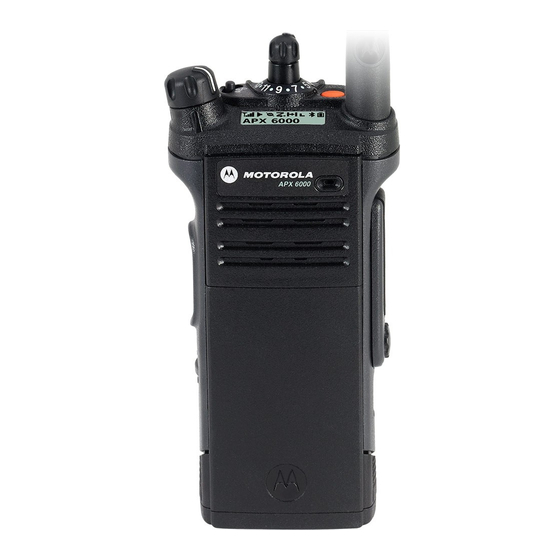
Page 26: Radio Parts And Controls
Radio Parts and Controls Antenna On/Off/Volume 16-Position Control Knob Select Knob* 3-Position A/B/C Microphone Display Switch* Top (Orange) 2-Position Concentric Button* Switch* Main Display Microphone Menu Select Top Side (Select) Accessory Buttons Button* Connector Main Speaker Push-to-Talk (PTT) Button Data Feature Bluetooth Button Pairing... -
Page 27: Programmable Features
Bluetooth Headset and PTT – Keys up the Bluetooth Programmable Features Headset's microphone. Any reference in this manual to a control that is Bluetooth Data Devices– Keys up the Bluetooth data devices. “preprogrammed” means that the control must be programmed Bluetooth Clear All Pairing –... - Page 28 Man Down – Prompts Emergency Alarm or Call when the radio Recent Calls – Allows for easy access to the list of calls achieves or passes a tilt angle threshold or a combination of the recently received or made. angle threshold and a motion sensitivity level. Rekey Request –...
-
Page 29: Assignable Settings Or Utility Functions
Text Messaging Service (TMS) – Selects the text messaging Accessing the Preprogrammed Functions menu. You can access various radio functions through one of the TMS Quick Text – Selects a predefined message. following ways: User – Automatically registers with the server. •... -
Page 30: Using The Navigation Buttons
Push-To-Talk (PTT) Button Using the Navigation Buttons Home Button The PTT button on the side of your radio serves two button returns you to the Home (default) screen. In most basic purposes : cases, this is the current mode. • While a call is in progress, For selected radio features, the button is also used to save... -
Page 31: Identifying Status Indicators
The following icons are for the front display screen unless Identifying Status Indicators indicated otherwise. Your radio indicates its operational status through the following: Receiving Radio is receiving a call or data. Status Icons ....... . . page 15 Text Messaging Service (TMS) Icons . - Page 32 Received Signal Strength Indicator (RSSI) In-Call User Alert The number of bars displayed represents the • On = The feature is enabled. Voice muting of received signal strength for the current site, for the affiliated trunking talkgroup or Top Display trunking only.
- Page 33 Priority Channel Scan Basic Zone Bank 2 Top Display • • Blinking dot = Radio detects activity on D = Radio is in Zone 4. channel designated as Top Display • E = Radio is in Zone 5. Priority-One. • F = Radio is in Zone 6.
- Page 34 AES Secure Operation Data Activity Data activity is present. • On = AES Secure operation. • Off = Clear operation. Bluetooth On • Blinking = Receiving an encrypted voice call. Bluetooth is on and ready for bluetooth connection. Location Signal Top Display •...
-
Page 35: Text Messaging Service (Tms) Icons
Text Messaging Service (TMS) Icons Read Message The selected text message in the Inbox has been This feature allows you to send and receive text messages. See read. Text Messaging Service (TMS) on page 65 for more Normal Message information. User is composing a message with normal priority and without a request for a reply. -
Page 36: Tms Menu Options
TMS Menu Options Request Reply • The “Request Reply” feature is toggled on Menu Option Description/Function before the message is sent. Back Brings you back to the previous screen. • Messages in the Inbox folder are flagged with “ Deletes all messages. Request Reply”. -
Page 37: Call Type Icons
Call Type Icons Landline phone number. The following icons appear on your radio’s main display, when you make or receive a call, or view selected call lists, to indicate the different call types associated with an alias or ID. Landline phone number added to a Call List. Radio number. -
Page 38: Led Indicator
Solid red – Radio is transmitting. LED Indicator Blinking red – Radio is transmitting at low battery condition. The LED indicator shows the operational status of your radio. Rapidly blinking red – Radio has failed the self test upon powering up or encountered a fatal error. Solid yellow (Conventional Only) –... -
Page 39: Intelligent Lighting Indicators
Intelligent Lighting Indicators This feature temporary changes the backlight of the top display screen, and adds a color bar to the main display screen to help signal that a radio event has occurred. Note: This feature must be preprogrammed by a qualified radio technician. Backlight and Bar Color Notification When... -
Page 40: Alert Tones
Alert Tones Your radio uses alert tones to inform you of your radio’s condition. The following table lists these tones and when they occur. You Hear Tone Name Heard Radio Self Test Fail When radio fails its power-up self test. Reject When an unauthorized request is made. - Page 41 You Hear Tone Name Heard Valid Key-Press When avcorrect key is pressed. Radio Self Test Pass When radio passes its power-up self test. Clear Voice At beginning of a non-coded communication. Short, Priority Channel Medium-Pitched When activity on a priority channel is received. Received Tone Emergency Alarm /Call...
- Page 42 You Hear Tone Name Heard Short, High-Pitched Low-Battery Chirp When battery is below preset threshold value. Tone (Chirp) Fast Ringing When system is searching for target of Private Call. Ringing Enhanced Call Sent When waiting for target of Private Call to answer the call. Phone Call Received When a land-to-mobile phone call is received.
- Page 43 You Hear Tone Name Heard Doh-Sol Enhanced Zone Bank Up When EZB Up button is pressed to scroll the Enhance Zone Bank up. Enhanced Zone Bank Sol-Doh When EZB Down button is pressed to scroll the Enhance Zone Bank down. Down English...
-
Page 44: Phone Call Display And Alert Prompts
Phone Call Display and Alert Prompts The following appears on the radio’s display when you make and receive Phone calls. The radio also uses alert tones to indicate the current status. You Hear You See When Notes You press the PTT button and the No phone Press to hang up. -
Page 45: General Radio Operation
Selecting a Zone General Radio Operation A zone is a group of channels. Once you understand how your APX 6000/APX 6000Li Portable is configured, you are ready to use your radio. Use this navigation guide to familiarize yourself with the basic... -
Page 46: Selecting A Radio Channel
Selecting a Radio Channel Follow the procedure below. < > A channel is a group of radio characteristics, such as transmit/ to Zone. receive frequency pairs. Press the Menu Select button directly below Zone. to the required zone. Press the Menu Select button directly below Sel to confirm the displayed zone. -
Page 47: Receiving And Responding To A Radio Call
Procedure: Receiving and Responding to a Radio Call Turn the preprogrammed 16-Position Select Knob to the desired channel. Once you have selected the required channel and/or zone, you can proceed to receive and respond to calls. Follow the procedure below. <... -
Page 48: Receiving And Responding To A Talkgroup Call
Receiving and Responding to a Talkgroup Call Receiving and Responding to a Private Call (Trunking Only) To receive a call from a group of users, your radio must be configured as part of that talkgroup. A Private Call is a call from an individual radio to another individual radio. -
Page 49: Receiving And Responding To A Telephone Call (Trunking Only)
During the call, the display shows the caller ID (number), if Procedure: the caller’s name is not in the call list. Use the preprogrammed Call Response button to answer a Telephone Call: Press and hold the PTT button to talk. Release the PTT button to listen. -
Page 50: Making A Radio Call
Making a Radio Call Press the PTT button to make the call. ASTRO Conventional Only: You can select a zone, channel, subscriber ID, or talkgroup by The LED lights up solid red. The display shows the using: talkgroup alias or ID. •... -
Page 51: Making An Enhanced Private Call (Trunking Only)
Making an Enhanced Private Call (Trunking Only) to the required ID. This feature allows you to send an individual Call Alert page if Press the PTT button to start the Private Call. there is no answer from the target radio. See Sending a Call Alert Page on page 51 for more information. -
Page 52: Making A Telephone Call (Trunking Only)
Press the PTT button to start the Private Call. Follow the procedure below. The display shows Calling... <Number>. < > to Phon. Hold the radio vertically 1 to 2 inches (2.5 to 5.0 cm) from Press the Menu Select button directly below Phon. The your mouth. -
Page 53: Repeater Or Direct Operation
Repeater or Direct Operation Monitoring Features The REPEATER operation increases the radio’s range by Radio users who switch from analog to digital radios often connecting with other radios through a repeater. The transmit assume that the lack of static on a digital channel is an and receive frequencies are different. -
Page 54: Conventional Mode Operation
Release the PTT button to receive (listen). Conventional Mode Operation ® Your radio may be preprogrammed to receive Private-Line (PL) calls. Press the preprogrammed Monitor button and proceed to Step 3. Procedure: Momentarily press the Monitor button to listen for activity. The Carrier Squelch indicator appears on the display. -
Page 55: Advanced Features
Advanced Call Features Advanced Features Use this navigation guide to learn more about advanced Receiving and Making a Selective Call (ASTRO features available with your radio: Conventional Only) Advanced Call Features ..... . . page 39 This feature allows you to receive a call from or to call a specific Contacts . -
Page 56: Making A Selective Call
Release the PTT button to listen. Making a Selective Call Press to hang up and return to the Home screen. Procedure: Press the preprogrammed Quick Access (One-Touch) Selective Call button to dial the preprogrammed ID and Using the Talkgroup Call Feature (Conventional proceed to Step 4. -
Page 57: Sending A Status Call
Press the Menu Select button directly below Sts. If the encryption key associated to the new talkgroup is erased, you hear a momentary key fail tone and the display The display shows the last acknowledged status call, or the shows Key fail. first status in the list. -
Page 58: Using The Dynamic Regrouping Feature (Trunking Only)
Using the Dynamic Regrouping Feature (Trunking Requesting a Reprogram (Trunking Only) Only) This feature allows you to notify the dispatcher when you want a This feature allows the dispatcher to temporarily reassign new dynamic regrouping assignment. selected radios to a particular channel where they can Procedure: communicate with each other. -
Page 59: Classifying Regrouped Radios
Classifying Regrouped Radios Entering the Dynamic Zone to Select a Dynamic Channel The dispatcher can classify regrouped radios into either of two categories: Select Enabled or Select Disabled. Procedure: < > to Zone. • Select-enabled radios are free to change to any available channel, including the dynamic-regrouping channel, once the Press the Menu Select button directly below Zone. -
Page 60: Deleting A Channel In The Dynamic Zone
Contacts to the required zone. Press the Menu Select button directly below Sel. The display shows Select Chan screen. This feature provides “address-book” capabilities on your radio. to the required channel. Press the Menu Select Each entry corresponds to an alias (name) or ID (number) that button directly below Sel. -
Page 61: Making A Private Call From Contacts
Your radio also supports a maximum of 50 call lists. Each list to the required subscriber alias. can store up to 100 IDs (numbers). Press the Menu Select button directly below Optn. Note: Your radio is preprogrammed with a number of to Call and press the Menu Select button directly contacts per Call Lists. -
Page 62: Adding A Contact To A Call List
Adding a Contact to a Call List Removing a Contact from a Call List Procedure: Procedure: < > < > to Cnts. to Cnts. Press the Menu Select button directly below Cnts. The Press the Menu Select button directly below Cnts. The entries are alphabetically sorted. -
Page 63: Scan Lists
Scan Lists Editing the Scan List This feature lets you change scan list members and priorities. Scan lists are created and assigned to individual channels/ Procedure: groups. Your radio scans for voice activity by cycling through the Long press the preprogrammed Scan List Programming channel/group sequence specified in the scan list for the current button (side button) and proceed to Step 3. -
Page 64: Changing The Scan List Status
Use the 16-Position Select knob to select additional Press the Select button one or more times to change the channels to be added or deleted. scan list status icon of the currently displayed channel. Move the Scan List Programming switch out of to select more list members whose scan status you programming position. -
Page 65: Viewing And Changing The Priority Status
Scan Viewing and Changing the Priority Status Procedure: This feature allows you to monitor traffic on different channels Below the Sel, Del, and Rcl screen, press the Menu Select by scanning a preprogrammed list of channels. button directly below Sel to view and/or change the priority status of the currently displayed channel. -
Page 66: Making A Dynamic Priority Change (Conventional Scan Only)
Making a Dynamic Priority Change (Conventional < > to Nuis. Press the Menu Select button directly below Scan Only) Nuis. While the radio is scanning, the dynamic priority change feature The radio continues scanning the remaining channels in the allows you to temporarily change any channel in a scan list list. -
Page 67: Call Alert Paging
Call Alert Paging Sending a Call Alert Page Note: The radio automatically exits the feature, if the feature This feature allows your radio to work like a pager. inactivity timer is enabled, when the radio is left idle Even if other users are away from their radios, or if they are and the timer expires. - Page 68 Press the Menu Select button directly below Yes to send If the call alert page is sent successfully, you hear a tone and the display shows Ack received. the call alert page. Press the Menu Select button directly below No to exit the If the call alert page is not acknowledged, you hear a low tone and the display shows No acknowledge.
-
Page 69: Emergency Operation
Emergency Operation Sending an Emergency Alarm This feature allows you to send a data transmission, which The Emergency feature is used to indicate a critical situation. identifies the radio sending the emergency, to the dispatcher. If the Top (Orange) button is preprogrammed to send an Note: Emergency button press timer by default is set to 1 emergency signal, this signal overrides any other... -
Page 70: Sending An Emergency Call (Trunking Only)
Release the PTT button to end the transmission and wait for Sending an Emergency Call (Trunking Only) a response from the dispatcher. This feature gives your radio priority access on a channel. Press and hold the preprogrammed Emergency button for Note: The radio operates in the normal dispatch manner about a second to exit the Emergency Call mode. -
Page 71: Sending A Silent Emergency Alarm
Note: For ALL Emergency signals, when changing channels: Hold the radio vertically 1 to 2 inches (2.5 to 5.0 cm) from your mouth. • If the new channel is also preprogrammed for Emergency, you can change channels while in Press and hold the PTT button. Speak clearly into the Emergency operation. -
Page 72: Fireground (Conventional Only)
The Fireground signals transmission is always exchanging data Fireground (Conventional Only) between your radio and the RF Modem and command terminal. The status of your radio includes The portable Fireground Communications System is designed for deployment at an incident scene. It consists of five central •... -
Page 73: Responding To Evacuation Indicator
Listen for a transmission. Adjust the Volume Control Knob if Responding to Evacuation Indicator necessary. When Incident Commander triggers Evacuation signal from his Press and hold the preprogrammed Volume Set button to command terminal, the RF Modem updates everyone in the hear the volume set tone. -
Page 74: Tactical Public Safety(Tps) (Conventional Only)
Tactical Public Safety(TPS) (Conventional Using TPS Emergency Transmission Only) Emergency Beacon – During Emergency if the TPS radio user pushes the Emergency button, the radio sounds a Beacon at the maximum volume of the radio at radio’s internal speaker Using TPS Normal Transmission and it is not adjustable. -
Page 75: Man Down
The Man Down feature has three phases: Man Down The radio senses the Man Down condition and Pre-Alert Man Down condition is determined based upon the radio tilt Timer is initiated. angle or a combination of radio tilt angle and the lack of radio Man Down condition continues for the time duration defined motion. -
Page 76: Pre-Alert Timer
Note: Emergency must be set up for this feature to operate. Post-Alert Timer For details on operating the Emergency alerts, please This timer sets the amount of time the radio needs to remain in see Emergency Operation on page 53. the Man Down condition before the Emergency alarm is transmitted. -
Page 77: Triggering Emergency
Triggering Emergency Re-Initiating Man Down When the user does not clear the Man Down condition and the After exiting the Emergency Operation when the radio is still in Post-Alert Timer comes to an end, Emergency Alarm or call is Man Down condition (tilted achieving threshold angle or triggered. -
Page 78: Testing The Man Down Feature
Testing the Man Down Feature Handling Man Down Functional Error Messages Procedure: Note: Enable the Emergency feature with Silent Alarm disabled, but not in Surveillance Mode before running If your radio display shows one of the following error this test on the radio. messages: Hardware board absent, Man-Down Hw error or Hw Board Mismatch. -
Page 79: Automatic Registration Service (Ars)
Advanced Automatic Registration Service (ARS) Selecting or Changing the ARS Mode Procedure: This feature provides an automated data application registration Turn the preprogrammed 16-Position Select knob, once the for the radio. When you turn on the radio, the device zone you want is displayed, to the desired mode. automatically registers with the server. -
Page 80: Accessing The User Login Feature
Press and hold to scroll through the list of predefined Accessing the User Login Feature usernames at a fast scroll rate. This feature allows you as the user to be associated with the Press the Menu Select button directly below Logn to select radio. -
Page 81: Logging Out
Text Messaging Service (TMS) Logging Out When you have logged in or you are using Offline mode, you This features allows you to quickly send and receive messages can log out. and run database queries directly from your radios. Procedure: The types of text messages available: Press the Menu Select button directly below Logt. -
Page 82: Accessing The Tms Features
Accessing the TMS Features Sending a Quick Text Message Quick Text messages are messages that are predefined and Note: The radio automatically exits the feature, if the feature usually consist of messages that are used most frequently. inactivity timer is enabled, when the radio is left idle and the timer expires. -
Page 83: Using The Priority Status And Request Reply Features
Press the Menu Select button directly below Optn. Using the Priority Status and Request Reply Features to Send Message and press the Menu Select button directly below Sel. Before sending your message, you can append a priority status and/or a request reply to your message. to scroll through the address list and highlight the required address. -
Page 84: Removing A Priority Status From A Text Message
Removing a Priority Status from a Text Message Removing a Request Reply from a Text Message Procedure: Procedure: Press the Menu Select button directly below Optn. Press the Menu Select button directly below Optn. to Mark as Normal and press the Menu Select to No Req Reply and press the Menu Select button button directly below Sel to remove the priority status from directly below Sel to remove the request reply icon from the... -
Page 85: Removing A Priority Status And A Reply Request From A Text Message
Removing a Priority Status and a Reply Request from Managing Text Messages a Text Message Receiving a Text Message Procedure: Note: When you receive a message that is flagged with the Press the Menu Select button directly below Optn. “Request Reply” icon, you must manually respond to to Mark as Normal and press the Menu Select the sender that you have received the message. -
Page 86: Viewing A Text Message From The Inbox
While on the view message screen, press the Menu Select Viewing a Text Message from the Inbox Rply Back button directly below , or to access the option. The Inbox can hold up to thirty (30) messages. • Rply Select to reply the message. -
Page 87: Managing Sent Text Messages
The display shows the Send Message screen and Follow the procedure below. Sending msg. < > to TMS. Back Press the Menu Select button directly below at any time to return to the previous screen. Press the Menu Select button directly below TMS to access the TMS feature screen. -
Page 88: Sending A Sent Text Message
Sending a Sent Text Message Deleting a Text Message Procedure: Procedure: Press the Menu Select button directly below Optn while From the Inbox or Sent screen: viewing the message. to scroll through the messages. to Send Message and press the Menu Select Press the Menu Select button directly below Del to delete button directly below Sel. -
Page 89: Deleting All Text Messages
Feature button to access the TMS feature screen, and proceed conventional channels. to Step 3. Unlike other forms of security, Motorola digital encryption provides signaling that makes it virtually impossible for others to Follow the procedure below. decode any part of an encrypted message. -
Page 90: Selecting Clear Transmissions
Selecting Clear Transmissions Managing Encryption Procedure: Loading an Encryption Key Turn the preprogrammed Secure/Clear switch to the clear position. Note: Refer to the key-variable loader (KVL) manual for equipment connections and setup. Note: If the selected channel is preprogrammed for secure- only operation –... -
Page 91: Using The Multikey Feature
Using the Multikey Feature Selecting an Encryption Key This feature allows the radio to be equipped with different Procedure: encryption keys and supports the DES-OFB algorithm. < > to Key. There are two types: Press the Menu Select button directly below Key. The •... -
Page 92: Selecting A Keyset
Selecting a Keyset Erasing the Selected Encryption Keys This feature allows you to select one or more groups of several This feature allows you to erase all or selected encryption keys. encryption keys from among the available keys stored in the Procedure: radio. -
Page 93: Requesting An Over-The-Air Rekey (Astro Only)
Use the preprogrammed Top Side (Select) button and Top Requesting an Over-the-Air Rekey (ASTRO Only) (Orange) button to erase the single key in radios with the This feature, also known as OTAR, allows the dispatcher to single-key option, and to erase all keys in radios with the reprogram the encryption keys in the radio remotely. -
Page 94: Mdc Over-The-Air Rekeying (Otar) Page
MDC Over-the-Air Rekeying (OTAR) Page Hear Clear This feature allows to view or define MDC Over-the-Air There are two components of Hear Clear. Rekeying (OTAR) features.It is applied only when operating in Companding: secure encrypted mode and only for conventional Reduces the channel noise, e.g. -
Page 95: The Global Positioning System (Gps)
• The Global Positioning System (GPS) Inside of buildings, trains, or other covered vehicles • Under any other metal or concrete roof or structure This feature uses information from the Global Positioning • Between tall buildings or under dense tree-cover System (GPS) satellites orbiting the Earth to determine the approximate geographical location of your radio, expressed as •... -
Page 96: Enhancing Gps Performance
The radio also stores four (4) preprogrammed waypoints. These Enhancing GPS Performance coordinates cannot be deleted. Sometimes, the GPS feature may be unable to complete a location calculation successfully. You then see a message Programmable Waypoints Preprogrammed Waypoints indicating that your radio cannot connect to enough visible Fixed location coordinates: satellites. -
Page 97: Accessing The Outdoor Location Feature
Press the Menu Select button directly below Rfsh to obtain Accessing the Outdoor Location Feature a new location fix. Note: An ON menu key may be present on the location menu The top line temporarily displays Please wait while the new if it is preprogrammed by the dealer or system location is being determined. -
Page 98: Saving A Waypoint
Saving a Waypoint Viewing a Saved Waypoint Procedure: Procedure: While in the current location display: While in the current location display: Press the Menu Select button directly below Optn. Press the Menu Select button directly below Optn. to Save as Waypt and press the Menu Select to Waypoints and press the Menu Select button button directly below Sel. -
Page 99: Deleting A Single Saved Waypoint
Deleting a Single Saved Waypoint Deleting All Saved Waypoints Procedure: Procedure: While in the current location display: While in the current location display: Press the Menu Select button directly below Optn. Press the Menu Select button directly below Optn. to Waypoints and press the Menu Select button to Waypoints and press the Menu Select button directly below Sel. -
Page 100: Measuring The Distance And Bearing From A Saved Waypoint
Measuring the Distance and Bearing from a Saved Using the Location Feature While in Emergency Waypoint Mode Procedure: When the Emergency feature is activated by pressing the While in the current location display: emergency button, the radio exits the Location menu and returns to the Home (default) screen so that you can see which Press the Menu Select button directly below Optn. -
Page 101: Trunking System Controls
Trunking System Controls Going Out of Range When your radio goes out of the range of the system, it can no longer lock onto a control channel. Using the Failsoft System Procedure: The failsoft system ensures continuous radio communications during a trunked system failure. If a trunking system fails You hear a low-pitched tone. -
Page 102: Locking And Unlocking A Site
Locking and Unlocking a Site Viewing and Changing a Site This feature allows your radio to lock onto a specific site. This This feature allows you to view the name of the current site or feature should be used with caution, since it inhibits roaming to forces your radio to change to a new one. -
Page 103: Mission Critical Wireless - Bluetooth
This feature allows your radio to extend its functionality by directly below On. The display shows Status On, and connecting to external proprietary Motorola Accessories. appears to indicate Bluetooth is on. The default setting for Bluetooth-enabled radio is Bluetooth ON. -
Page 104: Turning The Bluetooth Off
Turning the Bluetooth Off Re-Pair Timer Procedure: There are two options for configuring the radio’s Bluetooth pairing type. The type defines the duration the radio and the < > to BT. Press the Menu Select button directly below accessory retain the pairing information. BT to access the Bluetooth feature screen. -
Page 105: Bluetooth Drop Timer
Bluetooth Drop Timer Re-Pair Timer The Bluetooth Drop Timer has two different settings and Re-Pair Timer Scenarios Options functions, depending upon the selection of the Re-Pair Timer.: • When the radio is powered OFF, pairing Re-Pair Timer Drop Timer Options key is lost immediately, and accessory Options attempts to pair again. -
Page 106: Pairing Bluetooth Device With The Radio
Procedure: Pairing Bluetooth Device with the Radio Note: Bluetooth tones, Bluetooth menu and Preprogrammed buttons must be preprogrammed by a qualified radio technician. Check with your dealer or system administrator for more information. With your radio’s Bluetooth feature ON, and the Bluetooth tones enabled: Bluetooth Pairing... -
Page 107: Indicating Bluetooth Connection Is Lost
Turning On the Bluetooth Audio (Routing the If the connecting process is immediately following the Audio from the Radio to the Headset) pairing process and the connecting process fails to Procedure: complete within the 6 seconds, you hear a decremental- pitched tone to indicate unpaired. -
Page 108: Turning Off The Bluetooth Audio (Routing The Audio From The Headset To The Radio)
Turning Off the Bluetooth Audio (Routing the Adjusting the Volume of the Radio from Bluetooth Audio from the Headset to the Radio) Audio Device Procedure: Procedure: < > to BT. Press the Menu Select button directly below With the Bluetooth audio device connected to the radio: BT to access the Bluetooth feature screen. -
Page 109: Clearing All Bluetooth Devices Information
Press the Menu Select button directly below Back to return Clearing All Bluetooth Devices Information to the previous screen. Procedure: to the required device, press the Menu Select Long press the preprogrammed Bluetooth On/Off button. You button directly below Clr. hear a short, medium-pitched tone. -
Page 110: Viewing The Bluetooth Friendly Name
Programming Over Project 25 (POP 25) Viewing the Bluetooth Friendly Name (ASTRO 25 and ASTRO Conventional) Note: Your radio must be preprogrammed to allow you to use this feature. This feature enables configuration data to be upgraded to your Procedure: radio over-the-air. -
Page 111: Responding To The Notification Of Upgrade
Utilities Responding to the notification of Upgrade Procedure: Viewing the Recent Calls The display shows Upgrade?. This feature allows you to view the recent incoming and Press the Menu Select button below Acpt to accept the outgoing call information of the following call types: request to upgrade immediately. -
Page 112: Using The Flip Display
Procedure: Using the Flip Display Press the preprogrammed Recent Calls button and proceed to This feature allows you to reverse the content of the top display Step 3. upside down. It is particularly useful when you would like to read the top display while the radio is still in the carry holder attached Follow the procedure below. -
Page 113: Selecting An Enhanced Zone Bank
See Basic Zone Bank 1 and Basic Zone Bank 2 on page 17 Selecting the Power Level for more information on the status icons. This feature enables you to reduce the transmit power level for specific case that require a lower power level. You can select Selecting an Enhanced Zone Bank the power level at which your radio transmits. -
Page 114: Selecting A Radio Profile
The display shows Low power and the low power icon. Press the Menu Select button directly below Exit to exit the screen without making any changes. The display shows High power and the high power icon. The radio returns to the Home screen. The profile name on the Home screen indicates the current selected radio profile. -
Page 115: Selecting The Audio Speaker
to scroll through the menu selections. Selecting the Audio Speaker Press the Menu Select button directly below Sel to select This feature allows you to select the speaker route for the the radio profile with the required speaker routing. radio's audio from either the main or the secondary speaker using the radio profile settings. -
Page 116: Locking And Unlocking The Keypad And Controls
Note: The backlight remains on for a preprogrammed time Press the Menu Select button directly below Mute. before it automatically turns off completely or returns to The display shows momentary Tones off, indicating that the minimum backlight level. the keypad tones are disabled. Locking and Unlocking the Keypad and Controls The display shows momentary Tones on, and you hear a You can lock your radio’s keypad, programmable buttons, rotary... -
Page 117: Using The Time-Out Timer
Using the Time-Out Timer Setting the Time and Date This feature turns off your radio’s transmitter. You cannot You can set the time and date for your radio. transmit longer than the preset timer setting. Settings: If you attempt to do so, the radio automatically stops your •... -
Page 118: Using The Conventional Squelch Operation Features
Using the Conventional Squelch Operation Press the Menu Select button directly below Exit to exit the Features screen without making any changes and return to the Home This feature filters out unwanted calls with low signal strength or screen. channels that have a higher than normal background noise. Press the Menu Select button directly below Ok once you have finished to save your changes and return to the Home Analog Options... -
Page 119: Digital Options
Digital Options Using the PL Defeat Feature One or more of the following options may be preprogrammed in This feature allows you to override any coded squelch (DPL or your radio. Check with your dealer or system administrator for PL) that might be preprogrammed to a channel. The radio will also unmute to any digital activity on a digital channel. -
Page 120: Using The Smart Ptt Feature (Conventional Only)
Three variations of smart PTT are available: Using the Smart PTT Feature (Conventional Only) Mode Description Smart PTT is a per-personality, programmable feature used in conventional radio systems to keep radio users from talking Transmit Inhibit You cannot transmit if any traffic is over other radio conversations. -
Page 121: Impres™ Battery Annunciator
Press the Menu Select button directly below Exit to return to IMPRES™ Battery Annunciator the Home screen. This feature displays the current capacity and charges cycles of your battery when a IMPRES Battery is powering your radio. This feature must be enabled in your radio to see the Use the Options Menu. -
Page 122: Accessing The General Radio Information
Accessing the General Radio Information Accessing the Radio Information Your radio contains information on the following: This feature displays the following information of your radio: • Radio Information • • Host Version DSP Version • • • IP Display Secure Version KG (Secure Algorithm) •... -
Page 123: Viewing The Ip Information
Procedure: Viewing the IP Information Press the preprogrammed Info button and proceed to Step 3. This feature displays the device name, IP address, and status of your radio. Follow the procedure below. < > Note: The device name of your radio is preprogrammed. to Info. -
Page 124: Viewing The Control Assignments
Viewing the Control Assignments Voice Announcement This feature enables the radio to audibly indicate the current This feature displays the programmable radio functions feature mode, Zone or Channel the user has just assigned. This assigned to the controls of your radio for the currently selected audio indicator can be customized per customer requirements. - Page 125 Procedure: • Change to a new zone. The radio announces the current zone and channel it is transmitting. You hear a voice announcement when the features below are • Change to a new channel remaining within the current zone. preprogrammed in the radio. The radio announces the current channel.
-
Page 126: Helpful Tips
• (For APX 6000/ APX 6000Li R Radios Only) The APX 6000/APX 6000Li R radio is designed to be submerged to a maximum depth of 6 feet, with a maximum submersion time of 2 hours. Exceeding either maximum limit may result in damage to the radio. -
Page 127: Cleaning Your Radio
Cleaning Your Radio • (For APX 6000/APX 6000Li R Radios Only) Elastomer technology materials used for seals To clean the external surfaces of your radio: in rugged portable radios can age with time and a u t i o n environmental exposure. -
Page 128: Handling Your Radio
• Avoid subjecting the radio to an excess of liquids. Do not communication equipment in perfect operating condition. A submerge the radio unless it is a ruggedized, APX 6000/APX nationwide service organization is provided by Motorola to 6000Li R model. -
Page 129: Taking Care Of The Battery
Taking Care of the Battery Gauge Battery Charge Checking the Battery Charge Status 76% to 100% full* Your radio can indicate the battery’s charge status through: Top Display • the LED and sounds. • the fuel gauge icon on the display. You can also check the battery charge status via the menu entry. -
Page 130: Battery Recycling And Disposal
Battery Recycling and Disposal Gauge Battery Charge In the U.S. and Canada, Motorola participates in the nationwide Rechargeable Battery Recycling Corporation (RBRC) program for battery collection and recycling. Many retailers and dealers 11% to 25%* Top Display participate in this program. -
Page 131: Accessories
State the position of the vessel in distress, using any Appendix: Maritime Radio Use in the information that will help responders to locate you, e.g.: VHF Frequency Range • latitude and longitude • bearing (state whether you are using true or magnetic Take a moment to review the following: north) Special Channel Assignments. -
Page 132: Appendix: Maritime Radio Use In The Vhf Frequency Range
Table A-1: VHF Marine Channel List (Continued) Operating Frequency Requirements Frequency (MHz) Channel A radio designated for shipboard use must comply with Federal Number Transmit Receive Communications Commission Rule Part 80 as follows: 156.150 160.750 • on ships subject to Part II of Title III of the Communications Act, the radio must be capable of operating on the 156.800 156.200 160.800... - Page 133 Table A-1: VHF Marine Channel List (Continued) Table A-1: VHF Marine Channel List (Continued) Frequency (MHz) Frequency (MHz) Channel Channel Number Number Transmit Receive Transmit Receive 157.150 161.750 157.200 161.800 157.250 161.850 77** 156.875 – 157.300 161.900 156.925 161.525 157.350 161.950 156.975 161.575...
- Page 134 Highlights for the Accessories Accessories GPS only antenna is only used in either a single band UHF The accessory link below is for APX radios. Not all accessories or 700/800 application where the Public Safety Microphone are FCC certified for operation with all APX models and/or (PSM) is used with the corresponding PSM antenna.
-
Page 135: Glossary
Carrier Squelch squelch circuit silences the radio when no Automatic Registration Service signal is being received so that the user does not have to listen to “noise”. Motorola standard for wireless digital ASTRO 25 trunked communications. A software-controlled, computer-driven ASTRO... - Page 136 Light-emitting diode. A feature that allows the dispatcher to Li-Ion Lithium ion. Dynamic temporarily reassign selected radios to a Motorola Data Communication Regrouping single special channel so they can communicate with each other. Dynamic System Resilience Encrypted Integrated Data Electrical Serial Number...
- Page 137 Term Definition Term Definition A life-saving feature that senses the radio Network Access Code (NAC) operates on user may be in trouble by monitoring the Network Access digital channels to reduce voice channel whether the radio is in a vertical or Code interference between adjacent systems horizontal position or whether the radio is...
- Page 138 Term Definition Term Definition Push-To-Talk – the PTT button engages An operating condition whereby the radio’s the transmitter and puts the radio in Standby speaker is muted but still continues to transmit (send) operation when pressed. receive data. The part of the general frequency spectrum Pre-defined text messages that allow the Radio between the audio and infrared light...
- Page 139 Term Definition Coordinated Universal Time. The international time standard (formerly Greenwich Mean Time, or GMT). Zero hours UTC is midnight in Greenwich, England, which is located at 0 degrees longitude. Everything east of Greenwich (up to 180 degrees) is later in time; everything west is earlier.
-
Page 140: Commercial Warranty
Commercial Warranty Product manufactured by MOTOROLA. MOTOROLA assumes no obligations or liability for additions or modifications to this warranty unless made in writing and signed by an officer of MOTOROLA. Limited Warranty Unless made in a separate agreement between MOTOROLA and... - Page 141 H)Freight costs to the repair depot. Warranty service will be provided by MOTOROLA through one of its I) A Product which, due to illegal or unauthorized alteration of the authorized warranty service locations. If you first contact the software/firmware in the Product, does not function in company which sold you the Product (e.g., dealer or...
- Page 142 VI. PATENT AND SOFTWARE PROVISIONS: MOTOROLA will have no liability with respect to any claim of patent infringement which is based upon the combination of the Product or MOTOROLA will defend, at its own expense, any suit brought parts furnished hereunder with software, apparatus or devices not...
- Page 143 Motorola Solutions Australia’s limited warranty below is in addition to any rights and remedies you may have under the Australian Consumer Law. If you have any queries, please call Motorola Solutions Australia at 1800 457 439. You may also visit our website: http://www.motorola.com/Business/XA-EN/...
- Page 144 Notes English...
- Page 146 Schaumburg, Illinois 60196 U.S.A. MOTOROLA, MOTO, MOTOROLA SOLUTIONS and the Stylized M logo are trademarks or registered trademarks of Motorola Trademark Holdings, LLC and are used under license. All other trademarks are the property of their respective owners. © 2010–2012 Motorola Solutions, Inc. All rights reserved.