Table of Contents

Related Manuals for Jet SuperSaw JWSS-10CS


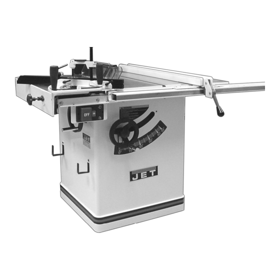
Summary of Contents for Jet SuperSaw JWSS-10CS
- Page 1 This manual is bookmarked Operating Instructions and Parts Manual SuperSaw Model: JWSS-10CS WMH TOOL GROUP 2420 Vantage Drive Elgin, Illinois 60124 Part No. M-708781 Ph.: 800-274-6848 Revision B 07/06 www.wmhtoolgroup.com Copyright © WMH Tool Group...
-
Page 2: Warranty And Service
Service Centers located throughout the United States can give you quick service. In most cases, any of these WMH Tool Group Authorized Service Centers can authorize warranty repair, assist you in obtaining parts, or perform routine maintenance and major repair on your JET® tools. For the name of an Authorized Service Center in your area call 1-800- 274-6848. -
Page 3: Table Of Contents
Table of Contents Warranty and Service... 2 Table of Contents... 3 Ordering Replacement Parts... 4 Warnings ... 5 Kickback Prevention... 7 Protection Tips from Kickback... 7 Specifications ... 7 Contents of the Shipping Containers ... 8 Accessory Package Box... 8 Sliding Table Box (optional accessory) ... -
Page 4: Ordering Replacement Parts
Troubleshooting ... 28 Parts ... 29 XACTA Fence II Homeshop 30/52 Fence Assembly ... 29 Cabinet Assembly... 30 Guard Assembly ... 31 Table Assembly ... 32 Sliding Table Assembly ... 35 Rail Assembly... 38 Motor & Trunnion Parts List... 40 Wiring Diagrams... -
Page 5: Warnings
4. This Table Saw is designed and intended for use by properly trained and experienced personnel only. If you are not familiar with the proper and safe operation of a Table Saw, do not use until proper training and knowledge has been obtained. - Page 6 xxxxxxxxxxxxxxxxxxxxxxxxxxxxxxxxxxxxxxxxxxxxxxxxxxxxxxxxxxxxx 21. Provide for adequate space surrounding work area and non-glare, overhead lighting. 22. Keep the floor around the machine clean and free of scrap material, oil and grease. 23. Keep visitors a safe distance from the work area. Keep children away. 24.
-
Page 7: Kickback Prevention
The most common accidents among table saw users, according to statistics, can be linked to kickback, the high-speed expulsion of material from the table that can strike the operator. Kickback can also result in operator’s hands being pulled into the blade. -
Page 8: Contents Of The Shipping Containers
Read and understand the entire contents of this manual before attempting assembly or operation! Failure to comply may cause serious injury Contents of the Shipping Containers Table saw Right Wing Extension Splitter Guard Assembly Accessory Package Owner’s Manual Warranty Card... -
Page 9: Left Wing Extension Box (Optional Accessory)
accessory) Left Wing Extension w/Miter Slot Miter Gauge Miter Gauge Bar Miter Gauge Handle Miter Gauge Fence Hardware Bag Socket Head Cap Screws M10x90 Lock Washers M10 Flat Washers M10 Hex Wrench 8mm XACTA Fence II Homeshop 30/52 Box One: XACTA Fence II Lock Lever Knob Box Two:... -
Page 10: Assembly
Assembly Unpacking and Clean-Up Do not connect the table saw to the power source until assembly has been completed! Failure to comply may cause serious injury! • Tool: 12mm Wrench 1. Remove all contents from the shipping container. Do not discard any shipping material until satisfactorily. -
Page 11: Mounting Rails
Mounting Rails Hardware: Front Rail, Rear Rail, (4) M8x16 Socket Head Cap Screws, (4) M8 Flat Washers, (4) Lock Washers, (2) 1/4-20 x 1-1/2 Hex Cap Screws, (4) 1/4” Flat Washers, (2) 1/4” Lock Washers, (2) 1/4” hex nuts. Tools: 6mm hex wrench, two 13mm wrenches Refer to Figures 4 and 5. -
Page 12: Miter Gauge For Left Extension Wing
Miter Gauge for Left Extension Wing Hardware: Miter Gauge Tools: Cross Point Screw Driver, Square 1. Change the angle on the miter gauge by loosening handle (E, Fig. 7) and turning the fence (F, Fig. 7) to desired angle. To move gauge beyond index stops of 45°... - Page 13 (B, Fig. 11) to rest on. This will help keep the sliding table the right height above the top of the table saw. 12. Use two jacking screws (G, Fig. 8) to raise the sliding table until it contacts the straight edge.
-
Page 14: Sliding Table Miter Gauge
Sliding Table Miter Gauge Hardware: Miter Gauge, Fence, (2) Handles, Stop, Fence Bar, Indicator Bar, Bushing, Bracket Clamp Assembly & (2) Handles Tools: 2.5mm Hex Wrench 1. Slide the miter gauge fence (B, Fig. 13) into the bar (A, Fig. 13) and attach to the miter gauge body (C, Fig. -
Page 15: Mounting The Switch Assembly
The optional wood extension table (including the optional router table) sits flush against the saw table and along the inside of the rails. The JET logo (or warning label on the router table) should face outward. The extension table is not bolted to the saw table, it is bolted only to the rails. -
Page 16: Guide Tube
(Figure 17). As one part of the edge becomes level with the table, tighten the clamp on that side. Then move to the other side and repeat, until the full length of the edge is level with the saw table. Lay a straight edge across both extension table and saw table to ensure proper leveling. -
Page 17: Xacta Fence
slot (A. Fig. 21), orient the guide tube (B) with respect to the rail (C) as shown in Figure 21. If your left table wing is the sliding table type (D, Fig. 22), mount the guide tube (F) so it lines up with the left edge on the angle iron portion of the rail (E). -
Page 18: Parallel To The Miter Slot Adjustment
(A, Fig. 27) the same number of turns until the space between the bottom of the fence and the table is the same. Care must be taken to raise or lower the fence on each side equally or the fence may not be 90° to the table after the height adjustment is performed. -
Page 19: Installing The Blade
Installing the Blade When installing or changing saw blade, always disconnect saw from power source! Failure to comply may cause serious injury! Hardware: Blade Tools: Arbor Wrench, Scrap Piece of Wood 1. Raise the blade arbor and make sure the arbor is at the zero degree position. -
Page 20: Blade Guard Assembly
Blade Guard Assembly Hardware: Blade Guard Assembly, Splitter Guard Assembly Tools: 12mm Wrench, 17mm Wrench or Adjustable Wrench, 3mm Hex Wrench 1. With a 3mm hex wrench, loosen two set screws (G, Fig. 34) on the splitter guard assembly and remove the bracket. 2. -
Page 21: Hooks For Miter Gauge And Fence
A qualified electrician must complete all electrical connections! Failure to comply may result in serious injury! The JWSS-10CS table saw is rated at 1-3/4 HP, 1Ph, 115V/230V prewired 115V. To switch the JWSS-10CS from 115V to 230V: Disconnect the machine from the power source, (unplug). -
Page 22: Grounding Instructions
Repair or replace a damaged or worn cord immediately. 115 Volt Operation Your table saw is set at the factory to run at 115- volt operation. When wired for 115 volt, this table saw is intended for use on a circuit that has an outlet and a plug that looks like the one illustrated in (A). -
Page 23: Adjustments
XACTA Fence Cursor Adjustment This adjustment must be checked whenever a different blade is installed. 1. Disconnect the table saw from the power source. 2. Raise the saw blade above the tabletop. 3. Unlock the fence and slide it to approximately four inches from the saw blade. -
Page 24: Adjusting 45° And 90° Positive Stops
Adjusting 45° and 90° Positive Stops The stops have been adjusted at the factory. After a period of use, or, after moving the saw to another location, the stops may no longer be set properly. To check and adjust the stops: Tool: 12mm Wrench, Combination 1. -
Page 25: Wear Adjustment In Raising Mechanism
Wear Adjustment in Raising Mechanism As the worm gear wears with time you may notice a little play in the handwheel. To adjust for wear in the raising mechanism: 1. Disconnect the machine from the power source, unplug. 2. Referring to Figure 48, remove the front panel (D) by unscrewing the lock knob (A), pulling off the handwheel (B) and removing five pan head screws (C) that hold the front panel. -
Page 26: Changing Poly V-Belt
Changing Poly V-Belt Make all machine adjustments or maintenance with the machine unplugged from the power source. Failure to comply may cause serious injury! 1. Disconnect the machine from the power source, unplug. 2. Lower the blade to its lowest point and tilt to 45°. -
Page 27: Maintenance
Maintenance General Maintenance Cabinet and Motor: Keep the inside of the cabinet clear of sawdust and wood chips. Vacuum out the inside of the cabinet and blow out the inside with an air hose. Make sure the motor fan and fan cover are also kept clear of sawdust. Worm Shafts and Trunnions: Use a wire brush and a cleaner/degreaser to clean worm shaft, and trunnions. -
Page 28: Troubleshooting
Troubleshooting Trouble Possible Cause Overload tripped Saw unplugged from wall or motor Fuse blown or circuit breaker tripped Saw stops or will not start Cord damaged Starting Capacitor is bad Centrifugal Switch bad or out of adjustment Stops not adjusted correctly Does not make Angle pointer not set accurately accurate 45°... -
Page 29: Parts
11 ...TS-0680021 ...Flat Washer... 1/4”... 2 12 ...HF2-112 ...Cursor ..1 13 ...HF2-113 ...XACTA Fence Label ..1 14 ...XF2-129 ...JET Label ..1 15 ...TS-0640071 ...Lock Nut ... 1/4”-20... 1 16 ...TS-0640081 ...Lock Nut ... 5/16”-18 ... 1 17 ...XF2-117 ...Spring Pin... -
Page 30: Cabinet Assembly
11 ...JWSS10CS-11...Dust Baffle (left) ..1 12 ...JWSS10CS-12...Dust Baffle (right) ..1 13 ...TS-2284082 ...Pan Head Screw ... M4 x 8 ... 6 14 ...LM000636 ...Warning Label ..1 15 ...LM000634 ...Angle Scale ..1 16 ...LM000629 ...JET Label ..1... -
Page 31: Guard Assembly
Guard Assembly Index No. Part No. Description Size 1 ...200321 ...Support Arm ..1 2 ...TS-2342061 ...Nylon Lock Nut... M6 ... 9 3 ...200322 ...Splitter ..1 4 ...200317 ...Spacer..2 5 ...TS-1482071 ...Hex Head Screw ... M6 x 35 ... 1 6 ...992501 ...Spring Nut ... -
Page 32: Table Assembly
Table Assembly Index No. Part No. Description Size 1 ...TS-1550061 ...Flat Washer... M8 ... 13 2 ...TS-1551061 ...Lock Washer ... M8 ... 7 3 ...TS-1490021 ...Hex Head Screw ... M8 x 16 ... 2 4 ...200324 ...Mounting Bracket ..1 5 ...TS-1490011 ...Hex Head Screw ... - Page 33 Table Assembly Index No. Part No. Description Size 58f ...200353 ...Switch Bracket ..1 58g ...200354 ...Switch Box ..1 58h ...998623 ...Strain Relief... 6W3-4S... 2 58i...TS-1540041 ...Hex Nut ... M6 ... 2 58j...TS-1550041 ...Flat Washer... M6 ... 2 58k...TS-1482011 ...Hex Head Screw ...
-
Page 35: Sliding Table Assembly
Sliding Table Assembly Index No. Part No. Description Size 1 ...200364 ...Sliding Table ..1 2 ...200411 ...Wiper Bracket w/Wiper ..4 3 ...200333 ...Sliding Rail ..2 4 ...200365 ...Sliding Table Plate ..1 5 ...TS-1490041 ...Hex Head Screw ... M8 x 25 ... 4 6 ...TS-1551021 ...Lock Washer ... - Page 36 Sliding Table Assembly Index No. Part No. 57 ...200374 ...90° Adjustable Plate... 0.02”... 2 58 ...NH061000...Nut... M6 ... 4 59 ...200430 ...Block ..1 60 ...TS-1522021 ...Set Screw... M5 x 8 ... 1 ...LM000633 ...Angle Label (not shown) ..1 ...JWSS10-STMGC...Sliding Table Miter Gauge Complete...
-
Page 38: Rail Assembly
Rail Assembly Index No. Part No..708783Z...Rail Assembly - Standard (30”) ..1 ...708782Z...Rail Assembly - Long Table (52”) ..1 1 ...SSX2-201...Front Fence Rail - Standard (30”)..1 ...SSX2-201A ...Front Fence Rail - Long Table (52”) ..1 2 ...200362 ...Back Fence Rail - Standard (30”) ... - Page 39 Rail Assembly...
-
Page 40: Motor & Trunnion Parts List
Motor & Trunnion Parts List Index No. Part No. 1 ...200310 ...Rear Trunnion Bracket..1 2 ...TS-1550061 ...Flat Washer... M8 ... 9 3 ...TS-1551061 ...Lock Washer ... M8 ... 10 4 ...TS-1490051 ...Hex Head Screw ... M8 x 30 ... 4 5 ...TS-2310162 ...Hex Nut ... - Page 41 Motor & Trunnion Parts List Index No. Part No. Description Size 51 ...200404 ...Handle..2 52 ...150045 ...Knob... M10 ... 2 53 ...200403 ...Hand Wheel ..2 54 ...200382 ...Pointer..1 55 ...200381 ...Spacer..1 56 ...TS-1522021 ...Socket Set Screw... M5x8 ... 2 57 ...200312 ...Front Trunnion Bracket ...
-
Page 43: Wiring Diagrams
Wiring Diagrams 115V Wiring... - Page 44 230V Wiring WMH Tool Group 2420 Vantage Drive Elgin, Illinois 60124 Phone: 800-274-6848 www.wmhtoolgroup.com...