Advertisement
Quick Links
FEATURES
1. Professional drum module with over 750 multi-sampled, Dynamic Articulation
2. Compact design is easy to fit into any setup, and mounts on stands or racks with built-in
mount zone
3. Works with 3-zone ride, continuous hi-hat control, and cymbals with choke capability
4. Premium instrument library multi-sampled from real drums and cymbals
5. Dynamic Articulation
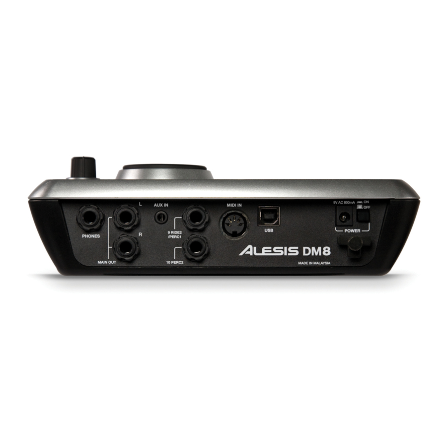
6. Main pad and trigger inputs via single-connection cable snake, plus two dual-zone
expansion inputs
7. Stereo 1/8" mix input for practicing with CD and MP3 players
8. Play along with tracks and record yourself with the sequencer and advanced metronome
9. USB MIDI for interface with software on Mac and PC; MIDI in for performance with
external controllers
SERVICE MANUAL
SPECIFICATION
changes sounds character along with dynamics for realism
™
MODEL: DM8
sounds
™
Advertisement

Related Manuals for Alesis DM8


Summary of Contents for Alesis DM8
- Page 1 SERVICE MANUAL MODEL: DM8 SPECIFICATION FEATURES 1. Professional drum module with over 750 multi-sampled, Dynamic Articulation sounds ™ 2. Compact design is easy to fit into any setup, and mounts on stands or racks with built-in mount zone 3. Works with 3-zone ride, continuous hi-hat control, and cymbals with choke capability 4.
-
Page 2: Testing The Power Supply
Use an AC volt meter and measure the AC voltage on the power supply output plug. It should be 9VAC to 12VAC. If the voltage is too high, it may damage the DM8 unit. Do not plug it into the DM8.Locate and correct the problem with the power supply or the AC Line voltage before continuing with the test. - Page 3 DM8 MP DIAGNOSTIC TEST PROCEDURE 3. Serial # Diags Serial # a) This is an informational display, not a test. If the unit has a valid serial number, pressing [PLAY] will display it on the LCD. 4. Ram Test Diags...
- Page 4 DM8 MP DIAGNOSTIC TEST PROCEDURE d) If the trigger micro responds with an error code, the LCD will display a message like this: Microcontroller CD12 stuck high See Appendix A for a chart of SW_MODE or TRIGGER number vs. actual signal name and rear panel jacks.
-
Page 5: Audio Tests
DM8 MP DIAGNOSTIC TEST PROCEDURE c) Once all switches are pressed and have been detected, the test will pass. If a switch is not working, press [STOP] twice to abort the test. The LCD will display the following: SWITCH Abort d) Press [STOP] one more time to return to the test selection menu. - Page 6 DM8 MP DIAGNOSTIC TEST PROCEDURE DAC to Main Outputs a) Connect both Main left and right outputs to the AP analyzer inputs. Because the Main left and right outputs are cross-wired to support mono mix from either jack, both the left and right channels must have something plugged in.
- Page 7 DM8 MP DIAGNOSTIC TEST PROCEDURE Aux In to Headphone Outputs a) Turn the Main level to minimum, and connect the Headphone output to the AP analyzer inputs. Set the AP analyzer input impedance to 600 Ohms. b) Connect the AP generator output to the AUX IN 1/8” TRS jack. Set the AP output to 2Vpp (-0.8dBu), 1KHz.
- Page 8 DM8 MP DIAGNOSTIC TEST PROCEDURE 13. USB Test Diags Additional equipment: Windows XP computer with a free USB port USB cable a) Connect the USB cable between the unit and the computer, then press [PLAY]. If everything is working, the test will finish in less than 1 second, then the LCD will display the following: Passed 14.
- Page 9 DM8 MP DIAGNOSTIC TEST PROCEDURE Note that the trigger level shown (displayed after “Trig 0 =”) will vary. There is no need to note the actual level unless it fails. All cables will have their TIPS tested. However, some cables will have additional tests the RING and/or SWITCH inputs.
-
Page 10: Additional Notes
DM8 MP DIAGNOSTIC TEST PROCEDURE ADDITIONAL NOTES: 1) During the tests, if the detected level is too high or too low, the LCD will display the one of the following: KICK CABLE Test TIP Level too high Trig 1 = 405... - Page 11 DM8 MP DIAGNOSTIC TEST PROCEDURE 15. Hihat Control Input test Additional equipment: Hihat Control input tester (see Appendix B) Diags HiHat a) Plug cable marked “hihat control” into the hihat tester and press [PLAY] (note that it must be done in this order).
- Page 12 Power-cycle the unit and enter normal operating mode Connect a MIDI cable from a MIDI keyboard (like MPK25) MIDI out jack to DM8 MIDI IN jack. Play keys on the keyboard. You should hear sounds come out of the Main TRS and Headphone audio outputs.
- Page 13 “USB Audio Device”. 7. Hold the [PREVIEW] button and scan the OLD serial number sticker 8. Look at the DM8 screen and make sure that it displays the serial number from the OLD barcode sticker. 9. Press the following buttons in this order: [REC], [F1], [F1], [F4], [METRO], [METRO], [F3], [F2] 10.
-
Page 14: Disassembly Procedures
DISASSEMBLY PROCEDURES DISASSEMBLE THE KNOB AND ROTATE WHEEL FROM TOP PANEL. (a)REMOVE ROTATE WHEEL, NUT AND WASHER FROM THE TOP PANEL. (b)REMOVE PLASTIC KNOB FROM THE TOP PANEL. (Fig1) DISASSEMBLE THE BOTTOM PLATE. (a)REMOVE 5 PCS OF NUTS FROM THE BOTTOM PLATE. (b)REMOVE 5 PCS OF SCREWS FROM THE BOTTOM PLATE. - Page 15 DISASSEMBLE THE CPU PCB ASS’Y. (a)REMOVE 4 PCS OF NUTS FROM THE CPU PCB ASS’Y (b)REMOVE 4 PCS OF SPRING WASHERS FROM THE CPU PCB ASS’Y (c)REMOVE 4 PCS OF WASHERS FROM THE CPU PCB ASS’Y (Fig3) DISASSEMBLE THE MAIN PCB ASS’Y. (a)REMOVE 6 PCS OF SCREWS FROM THE MAIN PCB ASS’Y (Fig4)
- Page 16 DISASSEMBLE THE LCD PCB ASS’Y. (a)REMOVE 2 PCS OF SCREWS AND COVER (LCM) AT LCD. (Fig5)
- Page 20 DM8 (BOM) Materials SPECS Part Location AL9-79-050903 CPU PCB Ass'y AA821786X CRYSTAL 11.289MHZ AL0-17-2470 R10~23 RES C.ARRAY 4X47 OHM 1/16W 5% ISOLATED C-C=0.5MM AL2-51-0140 DIODE POWER SCHOTTKY MBRS140LT3 40V 1A AL2-61-0431 REG ADJ-SHUNT LM431 2.5V-37V 100MA 2% SOT-23 AL9-40-0509 CPU PCB 6 LAYER FR-4 91X69 MM...
- Page 21 Materials SPECS Part Location C13~16, 78, 86, 89, 94, 97, 104, 113, CS102K1203X7R CCAP SMD 1000PF/100V 10% 0603 X7R 117, C125, 133, 137 CS103K5003X7R C.CAP 0.010UF 50V X7R,±10% SMD 0603 C4, 130, 131, 155 C1~3, 6, 10, 11, 21, 22, 24, 25, 43, 47, C54, 57, 64, 66, 69, 77, 90, 92, 99, 100, C103, 109, 110, 112, 116, 123, 127, 128, CS104K5003X7R...
-
Page 22: Safety Label
Materials SPECS Part Location R3, 12, 13, 51, 104~107, 128, 137, RS022010F03 CHIP RES. 220 Ω 1% SMD 0603 R145~147, 153, 167, 188, 199, 205, 212, R263 RS024010F03 CHIP RES. 240 Ω 1% SMD 0603 R245 RS033K10F03 CHIP RES. 33K Ω 1% SMD 0603 R87, 246 RS047010F03 CHIP RES. - Page 23 Materials SPECS Part Location SC0308RBBI SCREW SC0308RBNI SCREW WS073307IC WASHER WS663309IC SPRING WASHER 3M/M AL7-51-0154-O ALESIS SAFETY MANUAL REV.O AL7-91-1002 SILICAL GEL 5G PACKET CB513N037 NESTING CB513S066 LDM7 DIE-CUT PAD CGLDM7310ALE01 INNER CARTON (LDM7) CTLDM7513ALE01 OUTER CARTON (LDM7) 0.25 GEALE10...