Toro Reelmaster 3100-D Series Installation Instructions Manual
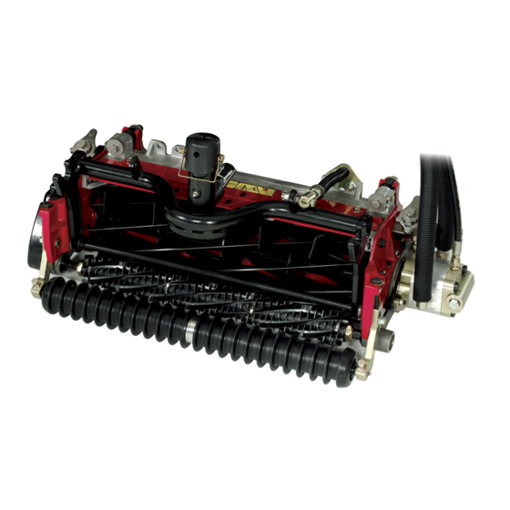
27-inch or 32-inch rear roller brush kit
Hide thumbs
Also See for Reelmaster 3100-D Series:
- Service manual (385 pages) ,
- Operator's manual (104 pages) ,
- Installation instructions manual (16 pages)
Table of Contents
Advertisement
Quick Links
27-inch or 32-inch Rear Roller Brush Kit
Reelmaster
Model No. 03186
Model No. 03187
Introduction
WARNING
CALIFORNIA
Proposition 65 Warning
This product contains a chemical or chemicals
known to the State of California to cause cancer,
birth defects, or reproductive harm.
This product complies with all relevant European directives.
For details, please see the Declaration of Incorporation (DOI)
at the back of this publication.
Contents
Introduction .................................................................. 1
Safety ........................................................................... 1
Safe Operating Practices........................................... 1
Setup ............................................................................ 2
1 Gathering the Appropriate Tools............................. 2
Brushes .............................................................. 3
3 Repositioning the Idler Pulley Assembly ................... 3
4 Removing the Brush Cover Drain Plug..................... 4
5 Installing the Roller Brush ...................................... 4
(Optional)........................................................... 9
Maintenance .................................................................10
Aligning the Pulleys ................................................10
Safety
Safe Operating Practices
•
Read, understand, and follow all instructions in the
traction-unit and cutting-unit operator manuals before
operating the cutting unit.
•
Read, understand, and follow all instructions in this
operator's manual before operating the brush kit.
•
Never allow children to operate the cutting units. Do not
allow adults to operate the traction unit or the cutting
units without proper instruction. Only trained operators
© 2015-The Toro® Company
8111 Lyndale Avenue South
Bloomington, MN 55420
®
3100-D and 7000-D Series DPA Cutting Unit
•
•
•
•
•
•
•
•
•
•
•
Register at www.Toro.com.
Installation Instructions
who have read this manual should operate the cutting
units.
Never operate the cutting units when under the influence
of drugs or alcohol.
Keep all shields and safety devices in place. If a shield,
safety device, or decal is illegible or damaged, repair or
replace it before operation is commenced. Also tighten
any loose nuts, bolts, and screws to ensure that the cutting
unit is in safe operating condition.
Always wear substantial, slip-resistant shoes. Do not
operate the cutting unit while wearing sandals, tennis
shoes, sneakers, or shorts. Also, do not wear loose-fitting
clothing which could get caught in moving parts. Always
wear long pants. Wearing safety glasses, safety shoes,
and a helmet is advisable and required by some local
ordinances and insurance regulations.
Remove all debris or other objects that might be picked
up and thrown by the cutting-unit blades. Keep all
bystanders away from the mowing area.
If the blades strike a solid object or the cutting unit
vibrates abnormally, stop and shut the engine off. Check
the cutting unit for damaged parts. Repair any damage
before starting and operating the cutting unit.
Lower the cutting units to the ground and remove the
key from the ignition switch whenever the machine is left
unattended.
Be sure that the cutting units and the brushes are in safe
operating condition by keeping the nuts, bolts, and screws
tight.
Remove the key from the ignition switch to prevent
accidental starting of the engine when servicing, adjusting,
or storing the machine.
Lightning can cause severe injury or death. If lightning
is seen or thunder is heard in the area, do not operate
the machine; seek shelter.
Perform only those maintenance instructions described in
this manual. If major repairs are ever needed or assistance
is desired, contact an Authorized Toro Distributor.
To ensure optimum performance and continued safety
certification of the machine, use only genuine Toro
replacement parts and accessories. Replacement parts
and accessories made by other manufacturers could be
dangerous, and such use could void the product warranty.
Original Instructions (EN)
All Rights Reserved *3395-107* A
Printed in the USA
Form No. 3395-107 Rev A
Advertisement
Table of Contents

Related Manuals for Toro Reelmaster 3100-D Series


Summary of Contents for Toro Reelmaster 3100-D Series
-
Page 1: Table Of Contents
• To ensure optimum performance and continued safety operator’s manual before operating the brush kit. certification of the machine, use only genuine Toro • Never allow children to operate the cutting units. Do not replacement parts and accessories. Replacement parts... - Page 2 Installation Loose Parts Use the chart below to verify that all parts have been shipped. Procedure Description Qty. – No parts required Gather the appropriate tools. Determine the position of the roller – No parts required brushes and reel motors. –...
-
Page 3: Gathering The Appropriate Tools
• 1/8 Allen wrench • 5/16 Allen wrench • 3/8-16 tap Figure 2 • 12 inch straight edge (Toro Part 114-5446) Reelmaster 7000-D • Torque wrench (foot-pound) 1. #1 cutting unit 5. #5 cutting unit • Torque wrench (inch-pound) 2. #2 cutting unit 6. -
Page 4: Removing The Brush Cover Drain Plug
1. Remove the idler pulley assembly from the left end of the cutting unit and mount it to the lower hole in the brush plate on the right end of the cutting unit (Figure Note: The idler pulley must pivot freely; do not over tighten the locknut on the idler pivot bolt. - Page 5 3. Remove the 2 bolts securing the counterweight to the left end of the cutting unit. Remove the counterweight (Figure Figure 7 1. Remove the nuts securing 3. Side-plate mounting flange each end of the roller. 2. 6 mm (1/4 inch) spacer 7.
- Page 6 Figure 11 5. Roller-brush mounting 1. Shoulder bolt bracket 2. Brush plate 6. Flange locknuts 3. Bolt 7. Roller-brush-bearing housing Figure 9 4. Grommet in bearing 1. Roller-brush mounting 3. Extra 6 mm (1/4 inch) housing bracket spacer 2. Cutting-unit side-plate mounting flange 11.
- Page 7 Figure 12 1. Loosen these bolts. Figure 14 1. Side-plate 4. Rear roller 2. Roller brush 5. Ensure that there is clearance here. 3. Light contact Note: The roller brush shaft must be parallel to the rear roller. Note: The orientation of the non-drive roller-brush-bearing housing should be the same as drive-side bearing housing.
- Page 8 • The outer faces of the drive and driven pulleys should be in line within 0.76 mm (0.030 inch). • If the pulleys are not aligned, Refer to Aligning the Pulleys (page 10). • If the pulleys are aligned, continue with the installation.
-
Page 9: Installing The High Height-Of-Cut Brush (Optional)
2. Slide the non-drive-bearing housing and the excluder seal off the brush shaft (Figure 21). Figure 19 Figure 21 1. Non-drive-bearing housing 3. Brush shaft 2. Excluder seal Installing the High 3. Remove the 2 J-bolts and nuts (Figure 22). Height-of-Cut Brush (Optional) Parts needed for this procedure: –... -
Page 10: Maintenance
8. Torque the J-bolt locknuts to 2 to 3 N-m (20 to 25 in-lb). 9. Install the excluder seal and the non-drive-bearing housing onto the brush shaft (Figure 21). 10. Mount the non-drive-bearing housing to the bearing-housing mounting bracket with the 2 bolts, washers, and nuts previously removed. - Page 11 Note: Seat the locknut, then torque it to 36 to 45 N-m (27 to 33 ft-lb). 8. Install the belt onto the pulleys as follows: • Loop the belt around the driven pulley and then over the top of the idler pulley (Figure 25).
- Page 12 The method of transmission shall be electronic transmittal. This machinery shall not be put into service until incorporated into approved Toro models as indicated on the associated Declaration of Conformity and in accordance with all instructions, whereby it can be declared in conformity with all relevant Directives.