
Related Manuals for Panasonic KX-TS3282B


Summary of Contents for Panasonic KX-TS3282B
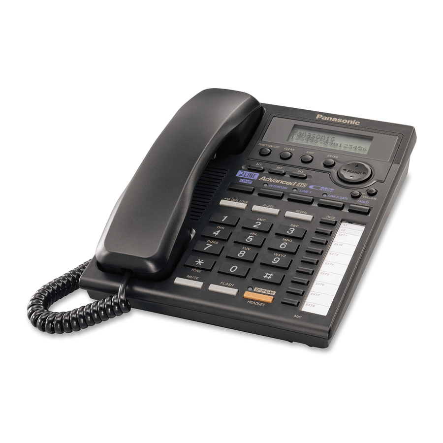
- Page 1 ORDER NO. KM40303053C1 Telephone Equipment KX-TS3282B Integrated Telephone System Black Version (for U.S.A.) SPECIFICATIONS...
-
Page 2: For Service Technicians
1. FOR SERVICE TECHNICIANS ICs and LSIs are vulnerable to static electricity. When repairing, the following precautions will help prevent recurring malfunctions. 1. Cover the plastic parts boxes with aluminum foil. 2. Ground the soldering irons. -
Page 3: Installing The Batteries
3. Use a conductive mat on the worktable. 4. Do not touch IC or LSI pins with bare fingers. 2. CAUTION Danger of explosion if battery is incorrectly replaced. Replace only with the same or equivalent type recommendenced by the manufacturer. Dispose of used batteries according to the manufacture’s Instructions. -
Page 4: Location Of Controls
Note: for Service Replace all three batteries if “ “ flashes. 4. LOCATION OF CONTROLS... - Page 6 5. Display 6. SETTINGS 6.1. Connections 6.1.1. Connecting the Handset and AC Adaptor...
- Page 7 6.1.2. Connecting Telephone Line Cords A maximum of eight KX-TS3282Bs can be connected in parallel. You can also connect KX- T3281W. To use the intercom, you must connect the telephone line cord to the LINE1/2 telephone jack of the unit.
- Page 8 - If another model telephone is connected to the KX-TS3282B except for KX-TS3281W, the line indicators of this unit will not function for that telephone. - If you re-connect the telephone line cord(s), confirm that all of the extension indicators light with the AC adaptor connected, then connect the telephone line cord(s).
- Page 10 - If you do not connect other extensions, you do not need to use a T- adaptor. Connect a 2-wire telephone line cord to the LINE1/2 telephone jack of the unit directly. 6.1.3. Connecting a Communication Device After connecting the telephone line cord to a two-line telephone jack, you can connect a communication device (computer, modem, fax, answering machine, etc.) through this unit using the LINE2/DATA jack.
- Page 11 - If the communication device is in use, use LINE 1 to make or answer other calls. Otherwise the communication device may not operate properly. 6.2. Dialing Mode If you have touch tone service, set to Tone. If rotary or pulse service is used, set to Pulse. Your phone comes from the factory set to Tone.
- Page 12 6.3. Dial Lock...
-
Page 13: How To Release The Establishment Of Dial Lock
6.4. How to Release the Establishment of Dial Lock... -
Page 14: Call Restriction
6.5. Call Restriction... - Page 16 7. OPERATIONS 7.1. Making Calls...
-
Page 18: Answering Calls
7.2. Answering Calls... - Page 19 7.3. FLASH Button...
- Page 20 7.4. Directory You can store up to 50 names and phone numbers in the directory. All directory items are sorted by the first word in alphabetical order. Using the directory, you can make a call by selecting a name on the display. Make sure that the handset is on the cradle, the AC adaptor is connected and the SP-PHONE/ HEADSET indicator light is off.
- Page 21 7.4.2. Selecting characters to enter names...
- Page 23 7.4.3. Finding Stored Items Make sure that the handset is on the cradle, the AC adaptor is connected and the SP-PHONE/ HEADSET indicator light is off.
- Page 25 7.4.4. Dialing...
- Page 27 7.4.5. Editing Make sure that the handset is on the cradle, the AC adaptor is connected and the SP-PHONE/ HEADSET indicator light is off.
- Page 29 7.4.6. Erasing Make sure that the handset is on the cradle, the AC adaptor is connected and the SP-PHONE/ HEADSET indicator light is off. 8. DISASSEMBLY INSTRUCTIONS...
-
Page 30: Troubleshooting Guide
Shown in Fig. To remove. Remove. Lower Cabinet Screws (2.6 × 12)......(A) × 5 Main P.C. Board Main P.C. Board Operational P.C. Board Screws (2.6 × 8)......(B) × 7 Operational P.C. Board 9. TROUBLE SHOOTING GUIDE ( )...Line 2 Cross Reference: Unit Does Not Turn On (SP-Phone) No Ringing Sound When a Ring Signal Is Input Problems with the Handset... -
Page 34: Problems With The Handset
9.2. Problems with the Handset... - Page 35 9.3. Unit Turns Off When Pulse Dialing...
- Page 36 9.4. Tone Dialing Problems 9.5. No Ringing Sound When a Ring Signal Is Input 9.6. Unit Does Not Hold...
- Page 37 9.7. If the Electronic Volume of the Speakerphone Does Not Work...
- Page 38 9.8. If the Electronic Volume of the Handset Does Not Work 9.9. Intercom Does Not Operate...
- Page 40 9.10. No LCD Display...
- Page 41 9.11. LED Is Not Turned On 9.12. No Caller ID Display...
-
Page 42: Test Mode
10. TEST MODE 10.1. Test Mode Flow Chart... -
Page 43: Telephone Line Interface
Signal Pass: Refer to SIGNAL ROUTE 11. BLOCK DIAGRAM 12. CIRCUIT OPERATIONS 12.1. Telephone Line Interface Circuit Operation: ( )...Line 2 This unit is connected to the telephone circuit by a 6-core full modular jack. When L1 (L2) key is pressed, the speakerphone goes ON automatically, obtaining Line 1 (Line 2). -
Page 44: Reset Circuit
becomes Low according to selected L1 (or L2), and Q130, Q131 (Q230, Q231) turned on and the Line Switch for that line (Line 1, Line 2) closes. Line current flows through Q130. As a result, a loop is formed through D101 (D201) Emitter of Q130 (Q230) Collector of Q130 (Q230) -
Page 45: Pulse Dial Circuit
Function: The tone dialing circuit consists of a DTMF (Dual Tone Multi Frequency) signal generator (outputted from) for tone dialing, and also a circuit for outputting the signal to line. The DTMF circuit indentifies inputs from the 12 keys (1, 2, 3, 4, 5, 6, 7, 8, 9, 0, ) by means of a total of seven frequencies, that is four low frequencies (Low group) and three high frequencies (High group). - Page 46 Attenuator, Comparator and Attenuator Control. The circuit analyzes whether the TX(transmit) or the RX(receive) signal is louder, and then it processed the signals such that the louder signal is given precedence. The Voice Detector provides a DC input to the Attenuator Control corresponding to the TX signal. The Comparator receives a TX and a RX signal, and supplies a DC input to the Attenuator Control corresponding to the RX signal.
- Page 47 (Holding) If the Hold key is pressed during a conversation using the handset or the speakerphone, the CPU IC801 judges that a hold status has been applied, consequently pin 67 (pin 65) of IC801 becomes High level, and PC4 (PC3) goes ON. Q132 and Q133 (Q232 and Q233) goes ON, and Q134 (Q234) goes ON, and the line voltage is held.
- Page 48 12.8.2. Data Communication Block 1. Data Transmission The oscillated waveform of 455 kHz (A) at pin 10 of IC701 becomes the tone burst signal (C) at pin 12 of IC701 by the data signal (B) from pin 31 of the microcomputer IC801. And then it passes the amplifier mixed with the audio FM signal and is transmitted to the telephone line via the transformer (T701).
- Page 49 *When an intercom transmission is not in use, the waveform of (D) becomes the same burst signal as (C). 2. Data Reception The data that is transmitted to the telephone line from another set is input via T701 in reverse order of the data transmission (D). This burst signal passes BPF701 to separate from the audio signal and then only 455 kHz is extracted (E) at pin 5 of IC701.
- Page 50 12.8.3. Voice Communication Block 1) Voice Transmission...
- Page 51 The transmitting signal from the H/S or SP-phone is input to CPI (the expander is used to reduce a noise generated by the transmission system, a cross talk of line transmission, pulse sound, or ring signal, etc.) and then output from CPO after compression according to the signal level. The audio signal compressed by the compander is amplified by Q701 and input to VMI for FM modulation/demodulation and output VTO after the FM modulation.
-
Page 52: Signal Route
Signal Pass: Refer to SIGNAL ROUTE 13. SIGNAL ROUTE... - Page 53 14. CPU DATA 14.1. IC801...
-
Page 54: Cabinet And Electrical Parts Location
15. CABINET AND ELECTRICAL PARTS LOCATION... -
Page 56: Accessories And Packing Materials
16. ACCESSORIES AND PACKING MATERIALS 17. HOW TO REPLACE FLAT PACKAGE IC 17.1. Preparation - SOLDER Sparkle Solder 115A-1, 115B-1 or Almit Solder KR-19, KR-19RMA - Soldering iron Recommended power consumption will be between 30 W to 40 W. Temperature of Copper Rod 662 ± 50°F (350 ± 10°C) (An expert may handle between 60 ~ 80 W iron, but beginner might damage foil by overheating.) - Flux... -
Page 57: Terminal Guide Of The Ics, Transistors And Diodes
Be certain each pin is located over the correct pad on the PCB. 2. Apply flux to all of the pins on the IC. 3. Being careful to not unsolder the tack points, slide the soldering iron along the tips of the pins while feeding enough solder to the tip so that it flows under the pins as they are heated. -
Page 58: Replacement Parts List
19. REPLACEMENT PARTS LIST Note: 1. RTL (Retention Time Limited) Note : The marking (RTL) indicates that the Retention Time is limited for this item. After the discontinuation of this assembly in production, the item will continue to be available for a specific period of time. The retention period of availability is depends on the type of assembly, and in accordance with the laws governing parts and product retention. - Page 59 3. The S mark means the part is one of some identical parts. For that reason, it may be different from the installed part. 4. ISO code (Example: ABS-94HB) of the remarks column shows quality of the material and a flame resisting grade about plastics. 5.
- Page 60 Ref. No. Part No. Part Name & Description Remarks PQAS57P03Z SPEAKER ABS-HB PQBC10374Z2 BUTTON, SP-PHONE KEY ABS-HB PQBX10366Z2 BUTTON, 17KEY ABS-HB PQBH10039Z2 BUTTON, HOOK ABS-HB PQBX10365Z2 BUTTON, 15KEY ABS-HB PQBX10367Z2 BUTTON, 9KEY PC-HB PQGP10224Z1 PANEL, LCD PQGT16080Z NAME PLATE PQHG10681Z RUBBER PARTS, SHEET PQHG10682Z RUBBER PARTS, SHEET...
- Page 61 Ref. No. Part No. Part Name & Description Remarks PCB1 PQWP1TS3282B MAIN P.C.BOARD ASS'Y (RTL) (ICS) IC101 PQVINJM2904F IC201 PQVINJM2904F IC301 PQVIBU8244F IC302 PQVIMC4094BF IC304 PQVIXCF3002P IC401 PQVISC77655V IC502 PQVIMT8843AS IC503 PQVITC4053BF IC601 PQVIPS3238NT IC602 PQVIPS3327UT IC603 PQVIBA78M08F IC701 PQVIXLA8231K IC801 C2CBGF000152 IC802...
- Page 62 Ref. No. Part No. Part Name & Description Remarks Q432 PQVTD143Z106 TRANSISTOR(SI) Q433 PQVTD143Z106 TRANSISTOR(SI) Q434 UN5113 TRANSISTOR(SI) Q450 PQVTD143Z106 TRANSISTOR(SI) Q481 2SD1819A TRANSISTOR(SI) Q482 PQVTD143Z106 TRANSISTOR(SI) Q483 PQVTD143Z106 TRANSISTOR(SI) Q601 2SC2235 TRANSISTOR(SI) Q602 2SD1819A TRANSISTOR(SI) Q701 2SD1819A TRANSISTOR(SI) Q702 2SD1819A TRANSISTOR(SI) Q703...
- Page 63 Ref. No. Part No. Part Name & Description Remarks (CERAMIC FILTERS) BPF701 J0B4553A0059 CERAMIC FILTER BPF702 J0B4103A0002 CERAMIC FILTER BPF703 J0B3703A0002 CERAMIC FILTER (COILS) L101 ELEV101KA COIL L102 PQLQXF330K COIL L103 PQLQXF330K COIL L104 PQLQXF330K COIL L105 PQLQXF330K COIL L702 PQL07A6 COIL L703...
- Page 64 Ref. No. Part No. Part Name & Description Remarks R118 ERJ3GEYJ562 5.6K R119 ERJ3GEYJ275 2.7M R120 ERJ3GEYJ563 R121 PQ4R10XJ225 2.2M R122 ERJ3GEYJ684 680K R123 ERJ3GEYJ104 100K R124 ERJ3GEYJ103 R125 ERJ3GEYJ680 R126 ERJ3GEYJ272 2.7K R127 ERJ3GEYJ333 R130 ERJ3GEYJ104 100K R131 ERJ3GEYJ102 R132 PQ4R18XJ472 4.7K...
- Page 65 Ref. No. Part No. Part Name & Description Remarks R218 ERJ3GEYJ562 5.6K R219 ERJ3GEYJ275 2.7M R220 ERJ3GEYJ563 R221 PQ4R10XJ225 2.2M R222 ERJ3GEYJ684 680K R223 ERJ3GEYJ104 100K R224 ERJ3GEYJ103 R225 ERJ3GEYJ680 R226 ERJ3GEYJ272 2.7K R227 ERJ3GEYJ333 R230 ERJ3GEYJ104 100K R231 ERJ3GEYJ102 R232 PQ4R18XJ472 4.7K...
- Page 66 Ref. No. Part No. Part Name & Description Remarks R355 ERJ3GEYJ823 R356 ERJ3GEYJ393 R357 ERJ3GEYJ183 R358 ERJ3GEYJ272 2.7K R359 ERJ3GEYJ394 390K R360 ERJ3GEYJ472 4.7K R361 ERJ3GEYJ563 R362 ERJ3GEYJ102 R363 ERJ3GEY0R00 R364 ERJ3GEYJ473 R365 ERJ3GEYJ224 220K R366 ERJ3GEYJ680 R368 ERJ3GEYJ104 100K R369 ERJ3GEYJ683 R370...
- Page 67 Ref. No. Part No. Part Name & Description Remarks R460 ERJ3GEYJ183 R461 ERJ3GEYJ332 3.3K R462 ERJ3GEYJ104 100K R463 ERJ3GEYJ472 4.7K R464 ERJ3GEYJ104 100K R465 ERJ3GEYJ222 2.2K R466 ERJ3GEYJ223 R481 PQ4R10XJ100 R482 ERJ3GEY0R00 R483 ERJ3GEYJ473 R484 PQ4R10XJ471 R508 ERJ3GEYJ104 100K R539 PQ4R18XJ100 R550 ERJ3GEYJ473...
- Page 68 Ref. No. Part No. Part Name & Description Remarks R728 ERJ3GEYJ103 R729 ERJ3GEYJ103 R730 ERJ3GEYJ222 2.2K R731 ERJ3GEYJ823 R732 ERJ3GEYJ103 R733 ERJ3GEYJ104 100K R734 ERJ3GEYJ123 R735 ERJ3GEYJ331 R736 ERJ3GEYJ273 R737 ERJ3GEYJ470 R738 ERJ3GEYJ103 R739 ERJ3GEYJ123 R740 ERJ3GEYJ123 R741 ERJ3GEYJ473 R742 ERJ3GEYJ224 220K R744...
- Page 69 Ref. No. Part No. Part Name & Description Remarks R830 ERJ3GEYJ104 100K R831 ERJ3GEYJ104 100K R832 ERJ3GEYJ104 100K R833 ERJ3GEYJ104 100K R834 ERJ3GEYJ104 100K R835 ERJ3GEYJ104 100K R836 ERJ3GEYJ104 100K R837 ERJ3GEYJ104 100K R840 ERJ3GEY0R00 R841 ERJ3GEYJ104 100K R846 ERJ3GEY0R00 R847 PQ4R18XJ100 J302...
- Page 70 Ref. No. Part No. Part Name & Description Remarks C234 ECEA1CKS100 C235 ECEA1EU101 C236 ECEA1HKS010 C253 ECEA0JKS101 C300 ECUV1H103KBV 0.01 C301 ECEA1CKA470 C302 ECEA1CKA470 C303 ECUV1C104KBV 0.1 C304 ECUV1H101JCV 100P C305 ECUV1H331JCV 330P C306 ECUV1H472KBV 0.0047 C307 ECEA0JKA221 C310 ECUV1H103KBV 0.01 C311 ECUV1H472KBV 0.0047 C312...
- Page 71 Ref. No. Part No. Part Name & Description Remarks C461 ECUV1C473KBV 0.047 C462 ECUV1E223KBV 0.022 C463 ECEA1CKA100 C464 ECEA1HKA4R7 C465 ECEA0JKA101 C466 ECEA1AKA101 C467 PQCUV1C105KB 1 C468 ECUV1C105ZFV C469 ECEA1AKA101 C470 ECEA1CU471 C471 ECUV1C104KBV 0.1 C472 ECUV1C104KBV 0.1 C473 ECUV1H103KBV 0.01 C481 ECEA0JKA101 C550...
- Page 72 Ref. No. Part No. Part Name & Description Remarks C728 ECUV1C105ZFV C729 ECUV1H333KBV 0.033 C730 ECUV1H272KBV 0.0027 C731 ECUV1C105ZFV C732 ECUV1C105ZFV C733 ECUV1C105ZFV C734 ECUV1C105ZFV C735 ECUV1C104KBV 0.1 C736 ECUV1C105ZFV C737 ECUV1C105ZFV C738 ECUV1C105ZFV C739 ECUV1C105ZFV C740 ECUV1A154KBV 0.15 C741 ECUV1H103KBV 0.01 C742 ECUV1H221JCV...
- Page 73 Ref. No. Part No. Part Name & Description Remarks PCB2 PQWP2TS3282B OPERATIONAL P.C.BOARD ASS'Y (RTL) (IC) IC605 C0HBZ0000038 (DIODES) D901 PSVD1SRCT D902 PSVD1SRCT D903 PSVD1SRCT D904 PSVD1SRCT D905 PSVD1SRCT D906 PSVD1SRCT D907 PSVD1SRCT D908 PSVD1SRCT D909 PSVD1SRCT D910 PSVD1SRCT D911 PSVD1SRCT D912 PSVD1SRCT...
-
Page 74: For Schematic Diagram
Ref. No. Part No. Part Name & Description Remarks KX-TCA1-G AC ADAPTOR PQJA10075Z CORD, TELEPHONE PQJA10088Z CORD, TELEPHONE PQJA212V CORD, CURL PQJXC0401Z HANDSET PQQX13437X INSTRUCTION BOOK PQQW12702Z QUICK GUIDE (for English) PQQW12703Z QUICK GUIDE (for Spanish) PQQW12576Z LEAFLET, #800 PQXDDS400-8 LABEL, SECURITY TAG PQPD10553Y CUSHION... - Page 75 M / KXTS3282B...
- Page 76 D904 SP-PHONE FLASH MUTE STB3 STB5 STB2 J905 STB1 R913 IC605 R901 R902 R904 D-LOCK PAGE PAUSE REDIAL LINE2 D903 LINE1 CONF HOLD D902 DOWN D901 R903 CN105 STB4 ENTER EXIT CLEAR FUN/EDIT KX-TS3282W CIRCUIT BOARD(Operation)Componet View...
- Page 77 CN105 J901 J903 KX-TS3282B CIRCUIT BOARD(Operation)Flow Solder Side View...
- Page 78 Q602, IC602 Q601 IC603 IC601 DTMF BATTERY SP-PHONE CS SP-PHONE VOL IC806 IC701 S_TONE DET. LCD DATA INTERCOM INTERFACE MOD/DEMOD CPU (IC801) C717 KEY A~D INTERCOM-CONT T701 MATRIX IC802 SP-PHONE, EXT1-8 EEPROM DRIVER LINE1, LINE2, INTERCOM KX-TS3282B: BLOCK DIAGRAM IC605...
- Page 79 Intercom TX (HS) R310 10(3216) HANDSET C304 C380 J100P R324 C307 C312 R321 J100P C209 J300 560K 6V220 R311 MIC+ R313 Q303 R318 R316 K0.027 K0.022 390K R319 C306 MIC- C303 100K K0.1 Q301 R328 R325 10K K4700P C308 Q300 J301 C816 Tel Line...
- Page 80 C742 410K 40 AGND 1.5K 1.8K 41 VCC K220P 42 MC (31) C716 K0.01 43 ME R719 44 OS C715 K0.01 R716 2.2K R715 R714 1.5K 4.7K (32) C714 Q702 BPF701 K330P R713 (33) 1.5K (34) KX-TS3282B SCHEMATIC DIARGRAM(Main) (35)
- Page 81 C742 410K 40 AGND 1.5K 1.8K 41 VCC K220P 42 MC (31) C716 K0.01 43 ME R719 44 OS C715 K0.01 R716 2.2K R715 R714 1.5K 4.7K (32) C714 Q702 BPF701 K330P R713 (33) 1.5K (34) KX-TS3282B SCHEMATIC DIARGRAM(Main) (35)
- Page 82 HOLD D905 R905 OUT8 OUT7 D903 R265 VOLDOWN PAGE R903 11 IN3 D903 12 IN2 FUNC D904 R904 14 DATA 15 CLK 17 VCC 18 LEDGND MIC 2 MICGND 21 Vatt+ 22 Vatt- J901 J902 KX-TS3282B SCHEMATIC DIARGRAM(Operation) J903 J904...
- Page 83 C454 R433 R463 C450 C464 C413 C467 R454 R455 IC401 C455 C468 Q450 R438 R465 C456 C446 R456 R464 C472 C458 C433 C471 R457 R441 Q435 C465 C459 D452 Q433 R448 C457 R442 D451 R400 KX-TS3282B CIRCUIT BOARD(Main)Componet View D450...
- Page 84 Q420 R421 R435 Q411 R420 R362 C559 R425 R559 C423 R416 C421 TPMODEM R423 C412 R410 R415 R466 TP404 R462 TP405 R437 C434 C435 R458 C473 R440 R439 C432 R434 C625 C431 Q432 KX-TS3282B CIRCUIT BOARD(Main)Flow Solder Side View SP-PHONE...