Advertisement
Quick Links
Advertisement

Related Manuals for NAKTO Discovery


Summary of Contents for NAKTO Discovery
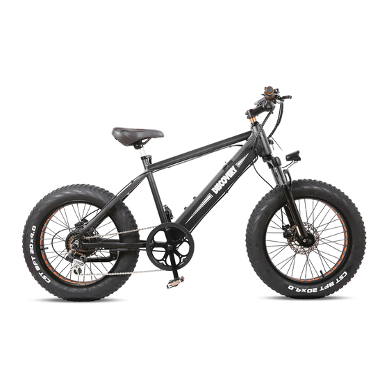
- Page 1 Discovery...
- Page 2 Keep the spare fuse in a safe place. It is not used for assembly and will be used for the replacement if the original fuse were damaged. Ensure all the following pieces are included with the Nakto Discov- ery.
- Page 3 2.Now stand the bike upright. Place some foam padding under the front fork if placed on the ground or put it on bike assembly/repair stand if you have one. We want to keep your bike looking new! Step Two: Assemble the front wheel. 1.Loosen axle nuts on front wheel to make room for the front fork.
- Page 4 3.Line up the axle lock washers (These are the metal washer with a bent tab on one side) with the hole at each fork. Notice: These two special fork lock washers keep the wheel from falling off if the axle nuts ever loosen up! Tighten the axle nuts by hand.
- Page 5 5.Push the black plastic nut caps onto the axle nuts. Step Three: Install the handlebar. 1.Loosen the bolt on the top of the stem with the supplied allen wrench. Remove the stem bolt and washer and set aside.
- Page 6 2.Remove and discard plastic spacer. 3.Install the handlebar onto the steer stem.
- Page 7 4.Pass the bolt through the washer mounting point and the stem mount, tighten with the supplied allen wrench part away. 5.Align the stem so the handlebar is perpendicular to the front wheel. Use the allen wrench to tighten the stem clamp bolts evenly (a half turn at a time alternating between the two bolts).
- Page 8 6.Tighten the bolt on the top of the stem with the supplied allen wrench. 7.Perform a twist test. (1).Brace the front wheel between your legs. (2).Switch hands so the opposite hands are pushing and pulling with about 20 pounds of force make sure the handlebar and front wheel are still properly aligned.
- Page 9 Step Four: Adjust the front brake system. NOTICE: The The adjustment of the front brake system is not easy. The following steps are only a general guide to assist in the adjustment of the front brake system. Consult a certified, reputable bike mechanic to assist with it.
- Page 10 On the front disc brake caliper there are two bolts mounting it to the front fork. Loosen the mounting bolts until the caliper body is able to freely move side to side. Then squeeze the brake lever ( this centers the caliper body over the rotor)...
- Page 11 If the pads are still rubbing, we need to do some fine-tuning. Loosen one bolt at a time and adjust until there is a gap on either side of the rotor. Once the pads are not rubbing, fully secure each mounting bolt and the process is complete.
- Page 12 Step Five: Install the headlight. 1.Remove headlight mounting bolt from the fork arch with the supplied screwdriver and set aside. 2.Attach the headlight to the fork arch. Pass the headlight mounting bolt through the headlight mount and the fork arch mounting point. Thread the locknut onto the bolt and tighten with the supplied screwdriver.
- Page 13 3.Center the headlight and adjust the angle slightly downwards to illumi- nate the road ahead and not blind oncoming traffic. Use the supplied Phillips-head screwdriver to loosen the headlight angle adjustment bolt, tilt the headlight to the optimal position, and then tighten in place securely.
- Page 14 Step Six: Install the seat. 1.Open the quick release lever by hinging it open fully. 2.Insert seat post into seat tube. Adjust the seat post up or down to a comfortable height, while ensuring the seat post is inserted into the frame past the minimum insertion point.
- Page 15 3.Close the quick release lever to secure the seat post and check that it cannot move. If needed, use the thumb nut to add tension to the clamp so there is some resistance when the lever is in line with the clamp bolt.
- Page 16 Step Seven: Install the pedals. 1.Locate the pedal with an “R” stamped into the end of the pedal axle, which indicate it is the right pedal. The right pedal goes on the crank on the right side of the bike. The remaining pedal with an “L” stamped into the end of the axle, is the left pedal.
- Page 17 Operate the electrical system when the battery has been adequately charged and the battery is secured to the frame mount. Your Nakto bike comes partially charged. We recommend you Connect the charger input plug (110/220-volt plug) to the power outlet for 3 to 4...
- Page 18 Step Ten: Ensure all hardware is tightened properly following recommended torque values. Recommended Torque Values: Hardware Location Hardware Torque Required (Nm) Front Dropout Area Front Axle Nuts Handlebar Area Handlebar Stem Clamp Bolts Handlebar Area Stem Bolts Handlebar Area Brake Lever Clamp Bolt Handlebar Area Shifter Clamp Screw Brakes...
- Page 19 Hardware Location Hardware Torque Required (Nm) Headlight Headlight Angle Adjustment Bolt Seatpost Area Seat Angle Adjustment Bolt Rear Dropout Area Rear Axle Nuts Rear Dropout Area Rear Torque Arm Bolt Rear Dropout Area Derailleur Hanger Mounting Bolt Rear Dropout Area Derailleur Mounting Bolt Rear Dropout Area Derailleur Cable Pinch...
- Page 20 Quick Start Guide This ebike is equipped with two ways for a rider to use power assistance from the motor to propel the bike forward: The pedal assist system (PAS) ⸺The rider can engage the pedal assist system (PAS) while pedaling, and it will call up assistance from the motor to help propel the bike forward.
- Page 21 4.Select the desired level of pedal assistance⸺Select the level from 0-5 by pressing “S+” and “S-” . Level 1 corresponds to the lowest level of pedal assistance, and level 3 corresponds to the highest level of pedal assistance. Level 0 indicates pedal assistance is inactive. Start in PAS level 0 or 1 and adjust from there.
- Page 22 6.The throttle is used by slowly and carefully rotating the throttle back- ward toward the rider. The more you twist, the more powerfully the throttle will propel the bike forward. Do not use the throttle while dismounted. Avoid accidental application of the throttle while dismounted;...
- Page 24 Switching off---Press and continue to hold down “CUR” to switching cruise control. Warning:Always keep at least one hand on a brake lever to allow quick cutoff of the motor assistance if necessary and to maintain control of the bike. The desired speed can be incorrectly adjusted or called up by mistake. There is a risk of an accident.
- Page 25 first ride. It is the user’ s responsibility to ensure a potential passenger on the Nakto eblike is adequately experienced and healthy enough to ride safely as a passenger. Serious injury or death can occur if passengers are inexperi- enced or in poor health such that it impacts their ability to ride as passen- gers safely.
- Page 26 ELECRTIC BICYCLE Trek Power Inc Toll Free: 1-855-997-7297 E-mail: support@nakto.com Website: www.nakto.com Adress:1683 Sierra Madre,Placentia,CA 92870...