Table of Contents
Advertisement
Quick Links
Service
Manual
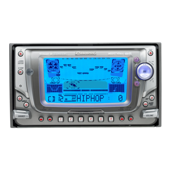
MULTI-CD/MD CONTROL DSP HIGH POWER CD CASSETTE PLAYER WITH RDS TUNER
FH-P6600R
MULTI-CD/MD CONTROL DSP HIGH POWER CD CASSETTE PLAYER WITH FM/AM TUNER
FH-P6600
- This service manual should be used together with the following manual(s):
Model No.
Order No.
CX-1011
CRT2406
CX-958
CRT2423
- Dolby noise reduction manufactured under license from Dolby Laboratories Licensing Corporation.
"Dolby" and the double-D symbol are trademarks of Dolby Laboratories Licensing Corporation.
- Three-color LEDs: The LCD backlight uses Hitachi's 3-color LEDs (NSCM315C) to control voltages for
RGB reproduction. By individually controlling the voltages for red, green and blue LEDs, these three
colors are mixed to reproduce ten colors.
CONTENTS
1. SAFETY INFORMATION ............................................2
2. EXPLODED VIEWS AND PARTS LIST .......................3
4. PCB CONNECTION DIAGRAM ................................42
5. ELECTRICAL PARTS LIST ........................................60
6. ADJUSTMENT..........................................................78
PIONEER CORPORATION
PIONEER ELECTRONICS SERVICE INC.
PIONEER ELECTRONIC N.V.
PIONEER ELECTRONICS ASIACENTRE PTE.LTD. 253 Alexandra Road, #04-01, Singapore 159936
C PIONEER CORPORATION 2000
FH-P6600R/EW
Mech. Module Remarks
3L
Cassette Mech. Module:Circuit Description, Mech.Description, Disassembly
S8.1
CD Mech. Module:Circuit Description, Mech.Description, Disassembly
4-1, Meguro 1-Chome, Meguro-ku, Tokyo 153-8654, Japan
P.O.Box 1760, Long Beach, CA 90801-1760 U.S.A.
Haven 1087 Keetberglaan 1, 9120 Melsele, Belgium
ES
7. GENERAL INFORMATION .......................................83
7.1 DIAGNOSIS ........................................................83
7.1.1 TEST MODE ..............................................83
7.1.2 DISASSEMBLY .........................................87
7.1.3 PCB LOCATIONS ......................................94
7.2 PARTS .................................................................95
7.2.1 IC................................................................95
7.2.2 DISPLAY ..................................................106
7.3 OPERATIONAL FLOW CHART .........................108
8. OPERATIONS AND SPECIFICATIONS...................109
ORDER NO.
CRT2502
EW
K-ZZU. MAY 2000 Printed in Japan
Advertisement
Table of Contents

Related Manuals for Pioneer FH-P6600R EW


Summary of Contents for Pioneer FH-P6600R EW
-
Page 1: Table Of Contents
PIONEER ELECTRONICS SERVICE INC. P.O.Box 1760, Long Beach, CA 90801-1760 U.S.A. PIONEER ELECTRONIC N.V. Haven 1087 Keetberglaan 1, 9120 Melsele, Belgium PIONEER ELECTRONICS ASIACENTRE PTE.LTD. 253 Alexandra Road, #04-01, Singapore 159936 C PIONEER CORPORATION 2000 K-ZZU. MAY 2000 Printed in Japan... -
Page 2: Safety Information
FH-P6600R,P6600 - CD Player Service Precautions 2. During disassembly, be sure to turn the power off 1. For pickup unit(CXX1285) handling, please refer since an internal IC might be destroyed when a con- to"Disassembly"(see page 87). nector is plugged or unplugged. During replacement, handling precautions shall be 3. -
Page 3: Exploded Views And Parts List
FH-P6600R,P6600 2. EXPLODED VIEWS AND PARTS LIST 2.1 PACKING(FH-P6600R/EW) 17 17... - Page 4 FH-P6600R,P6600 NOTE: - Parts marked by "*"are generally unavailable because they are not in our Master Spare Parts List. ∇ mark on the product are used for disassembly. - Screws adjacent to - PACKING SECTION PARTS LIST Mark No. Description Part No.
- Page 5 FH-P6600R,P6600 2.2 PACKING(FH-P6600/ES)
- Page 6 FH-P6600R,P6600 - PACKING SECTION PARTS LIST Mark No. Description Part No. 1 Screw Assy CEA2189 2 Screw BMZ50P060FMC 3 Polyethylene Bag CEG-127 4 Screw CMZ50P060FMC 5 Polyethylene Bag CZE3188 6-1 Polyethylene Bag CEG1116 6-2 Owner’s Manual CRD3241 6-3 Installation Manual CRD3242 7 Battery CEX1006...
- Page 7 FH-P6600R,P6600 2.3 EXTERIOR...
- Page 8 FH-P6600R,P6600...
- Page 9 FH-P6600R,P6600 (1) EXTERIOR SECTION PARTS LIST Mark No. Description Part No. Mark No. Description Part No. 1 Screw BMZ26P060FMC 46 Case CNC8873 2 Screw BMZ26P250FMC 47 Insulator CNM5967 3 Screw BSZ26P060FMC 48 ••••• 4 Screw BSZ30P060FMC 49 Insulator See Contrast table(2) 5 Screw BSZ30P080FMC 50 FM/AM Tuner Unit...
- Page 10 FH-P6600R,P6600 Mark No. Description Part No. Mark No. Description Part No. 91 Clamper CNV6309 136 Battery Cover See Contrast table(2) 92 Chassis Unit CXB5420 137 Cord Assy See Contrast table(2) EXK4020 138 Cap See Contrast table(2) Cassette Mechanism Module 94 Screw BPZ20P080FMC 139 Resistor See Contrast table(2)
- Page 11 FH-P6600R,P6600 (2) CONTRAST TABLE FH-P6600R/EW and FH-P6600/ES are constructed same except for the following: Part No. Mark No. Symbol and Description FH-P6600R/EW FH-P6600/ES 13 Cord Assy CDE6404 Not used 14 Fuse(10A) CEK1136 Not used 15 Cap CKX-003 Not used 16 Cap CNS1472 Not used 17 Resistor...
- Page 12 FH-P6600R,P6600 2.4 CD MECHANISM MODULE...
- Page 13 FH-P6600R,P6600 - CD MECHANISM MODULE SECTION PARTS LIST Mark No. Description Part No. Mark No. Description Part No. 1 Control Unit(S8TX) CWX2434 46 ••••• 2 Connector(CN802) CKS2192 47 Ball CNR1189 3 Connector(CN801) CKS2193 48 Belt CNT1086 4 Connector(CN701) CKS4281 49 Roller CNV4509 5 Connector(CN101) CKS3486...
- Page 14 FH-P6600R,P6600 2.5 CASSETTE MECHANISM MODULE...
- Page 15 FH-P6600R,P6600 - CASSETTE MECHANISM MODULE SECTION PARTS LIST Mark No. Description Part No. Mark No. Description Part No. 1 Screw BSZ20P040FMC 46 Pinch Roller ENV1518 2 Washer CBF1037 47 Pinch Holder Unit EXA1583 3 Washer CBG1003 48 Pinch Roller ENV1518 4 Screw EBA1028 49 Reel Unit...
-
Page 16: Block Diagram And Schematic Diagram
FH-P6600R,P6600 3. BLOCK DIAGRAM AND SCHEMATIC DIAGRAM 3.1 BLOCK DIAGRAM(EW model) AUDIO AMP UNIT FM/AM TUNER UNIT Q403 Q406 FM FRONT END FM/AM 1ST IF 10.7MHz Q405 CN451 Q407 ANTENNA T51 Q51 CF51 CF52 CF53 L-OUT IC 2 PM4008A Q501 34 33 DECODER MIXER, IF AMP DET... - Page 17 FH-P6600R,P6600 Q408 CN801 MOTOR IC 805 FLAP0 BA6288FS FLAP1 UNIT Q802 Q801 tmute FM/am FLAPPW SYSTEM SLIDE POSITION SENSE Q803 MICRO COMPUTER — X601 IC 804 6.291456MHz IC 601 (1/2) BACK GP1S94J ldet — PE5124A — IC 801 NL2DT FLSEN1 SW5V TC7W14FU FLSEN0...
- Page 18 FH-P6600R,P6600 3.2 OVERALL CONNECTION DIAGRAM(GUIDE PAGE) Note: When ordering service parts, be sure to refer to “EXPLODED VIEWS AND PARTS LIST” or “ELECTRICAL PARTS LIST”. CONTROL UNIT CN701 CN602 Large size SCH diagram Guide page CN251 Detailed page TAPE :-9dBs FM(100%)EW :-15.5dBs FM(100%)ES :-19.5dBs...
- Page 19 FH-P6600R,P6600 AUDIO AMP UNIT FM(100%)EW :+8.2dBs FM(100%)ES :+4.2dBs AM(30%)EW :-2.3dBs FM(100%)EW :-4.4dBs AM(30%)ES :-6.3dBs FM(100%)ES :-8.4dBs IP-BUS :+10.2dBs AM(30%)EW :-14.9dBs :+11.2dBs AM(30%)ES :-18.9dBs TAPE :-3.8dBs IP-BUS :-2.4dBs :-1.4dBs TAPE :-16.4dBs FM(100%)EW :-6.8dBs FM(100%)ES :-10.8dBs AM(30%)EW :-17.3dBs AM(30%)ES :-21.3dBs IP-BUS :-4.8dBs TAPE :-18.8dBs FM(100%)EW :+3.2dBs...
- Page 20 FH-P6600R,P6600...
- Page 21 FH-P6600R,P6600...
- Page 22 FH-P6600R,P6600...
- Page 23 FH-P6600R,P6600...
- Page 24 FH-P6600R,P6600 3.3 FM/AM TUNER UNIT(FH-P6600R/EW) FM/AM TUNER UNIT Mark Band Input Level None – – 0dBf 65dBf F125 125dBf 0dBµ 74dBµ A125 125dBµ...
- Page 25 FH-P6600R,P6600...
- Page 26 FH-P6600R,P6600 3.4 FM/AM TUNER UNIT(FH-P6600/ES) FM/AM TUNER UNIT Mark Band Input Level None – – 0dBf 65dBf F125 125dBf 0dBµ 74dBµ A125 125dBµ...
- Page 27 FH-P6600R,P6600...
- Page 28 FH-P6600R,P6600 3.5 POWER SUPPLY UNIT...
- Page 29 FH-P6600R,P6600 POWER SUPPLY UNIT...
- Page 30 FH-P6600R,P6600 3.6 FLAP PCB CN1201 TAPE D.FUNC CN1102...
- Page 31 FH-P6600R,P6600 FLAP PCB UNIT FLAP PCB UNIT Consists of FLAP PCB LED PCB...
- Page 32 FH-P6600R,P6600 3.7 LED PCB...
- Page 33 FH-P6600R,P6600 3.8 PANEL PCB UNIT PANEL PCB UNIT CN854 CN1901...
- Page 34 FH-P6600R,P6600 CONTROL UNIT(S8TX) 3.9 CD MECHANISM MODULE PICKUP UNIT (SERVICE)(P8) CN101 RF-AM PHOTO UNIT(S8) CN802 Q1 CPT230SX-TU Q2 CPT230SX-TU SPINDLE MOTOR M3 CXB5829 CARRIAGE MOTOR M1 CXB5827 LOADING MOTOR CD DRIVER M2 CXB5828 CN801 5V REGULATOR...
- Page 35 FH-P6600R,P6600 SWITCHES: CONTROL UNIT S801 : HOME SWITCH..ON-OFF S802 : CLAMP SWITCH..ON-OFF The underlined indicates the switch position. CN601 RF-AMP, SERVO, DSP, DAC, LPF CN602 CN251 CN701...
- Page 36 FH-P6600R,P6600 Note:1. The encircled numbers denote measuring pointes in the circuit diagram. 2. Reference voltage REFO:2.5V - Waveforms 1 RFI 1 CH1: RFI 1 CH1: RFI 0.5V/div. 0.5µs/div. 1V/div. 1V/div. 0.5ms/div. 0.5ms/div. 2 CH2: MIRR 2 CH2: MIRR Normal mode: play 5V/div.
- Page 37 FH-P6600R,P6600 8 CH1: TE 8 CH1: TE 0 MD 0.2V/div. 0.5V/div. 0.5V/div. 0.1s/div. 20ms/div. 5ms/div. 9 CH2: TD ! CH2: SD 0.2V/div. 0.5V/div. Normal mode: play TEST mode: 100 Tracks jump(FWD) Normal mode: Play (12cm) → REFO → REFO → REFO →...
- Page 38 FH-P6600R,P6600 1 CH1: RFI 6 CH1: FE 8 CH1: TE 0.2V/div. 0.2V/div. 1V/div. 1ms/div. 1ms/div. 0.5ms/div. 9 CH2: TD ⁄ CH2: HOLD 3 CH2: FD 0.5V/div. 0.5V/div. 5V/div. Normal mode: During AGC Normal mode: During AGC Normal mode: The defect part passes 800µm(B.D) →...
- Page 39 FH-P6600R,P6600...
- Page 40 FH-P6600R,P6600 3.10 CASSETTE MECHANISM MODULE DECK UNIT CN252 VR302 CCP1280 Q271 33K(B) 2SC4116 R260 R258 C253 390P Rev-L R283 0R0 R256 C254 390P Rev-R NFI(L) MSGV(R) R284 0R0 R403 MAOUT RIN(L) C271 R291 C404 R01 IC251 Fwd-R R282 0R0 1/50 MSDET FIN(L) C252 390P...
- Page 41 FH-P6600R,P6600 M1 MOTOR UNIT (MAIN MOTOR) EXA1490 CN255 CN256 REEL SENSE CN253 EGN1 EGN1004 Q271 2SC4116 R277 R375 70µs 220K MODE R373 load LOAD R275 ESG1007x3 C405 R033 REEL SENSE R404 270K CN254 MOTOR UNIT (SUB MOTOR) VCC2 EXA1580 R374 MECHANISM DRIVER C356...
-
Page 42: Pcb Connection Diagram
FH-P6600R,P6600 4. PCB CONNECTION DIAGRAM AUDIO AMP UNIT 4.1 AUDIO AMP UNIT CORD CN902 NOTE FOR PCB DIAGRAMS 1. The parts mounted on this PCB include all necessary parts for several destination. For further information for respective destinations, be sure to check with the schematic diagram. - Page 43 FH-P6600R,P6600 SIDE A CN903 IP-BUS ANTENNA IC,Q CN251 CN1101 CN701 FRONT...
- Page 44 FH-P6600R,P6600 AUDIO AMP UNIT IC,Q FOPN FCLS...
- Page 45 FH-P6600R,P6600 SIDE B...
- Page 46 FH-P6600R,P6600 4.2 FM/AM TUNER UNIT SIDE A...
- Page 47 FH-P6600R,P6600 SIDE B...
- Page 48 FH-P6600R,P6600 4.3 POWER SUPPLY UNIT POWER SUPPLY UNIT CN856...
- Page 49 FH-P6600R,P6600 SIDE A IC,Q RCA CORD CN857...
- Page 50 FH-P6600R,P6600 POWER SUPPLY UNIT IC,Q...
- Page 51 FH-P6600R,P6600 SIDE B...
- Page 52 FH-P6600R,P6600 4.4 FLAP PCB SIDE A FLAP PCB CN1201...
- Page 53 FH-P6600R,P6600 FLAP PCB SIDE B CN1102...
- Page 54 FH-P6600R,P6600 4.5 LED PCB LED PCB LED PCB SIDE A SIDE B CN1902...
- Page 55 FH-P6600R,P6600 4.6 PANEL PCB UNIT PANEL PCB UNIT CN1901 CN854 CASSETTE DOOR DETECTOR PANEL PCB UNIT...
- Page 56 FH-P6600R,P6600 4.7 CD MECHANISM MODULE SIDE A...
- Page 57 FH-P6600R,P6600 SIDE B...
- Page 58 FH-P6600R,P6600 4.8 CASSETTE MECHANISM MODULE DECK UNIT SIDE A CN111 CN251 DECK UNIT SIDE B HEAD ASSY IC,Q VR302 CN254 CN255 Q271 CN253 CN252 IC253 IC251 Q351 Q352 VR301 CN256...
- Page 59 FH-P6600R,P6600 REEL SENSE PCB LOAD SW 70µs SW MODE SW CN256 EGN1 REEL SENSE CN253...
-
Page 60: Electrical Parts List
FH-P6600R,P6600 5. ELECTRICAL PARTS LIST NOTES: - Parts whose parts numbers are omitted are subject to being not supplied. - The part numbers shown below indicate chip components. Chip Resistor RS1/_S___J,RS1/__S___J Chip Capacitor (except for CQS..) CKS.., CCS.., CSZS..=====Circuit Symbol and No.===Part Name Part No. - Page 61 FH-P6600R,P6600 =====Circuit Symbol and No.===Part Name Part No. =====Circuit Symbol and No.===Part Name Part No. ------ ------------------------------------------ ------------------------- ------ ------------------------------------------ ------------------------- CCSRCH220J50 CKSRYB473K16 CCSRCH150J50 CKSQYB334K16 CCSRCH8R0D50 CKSQYB474K16 CCSRCJ3R0C50 CKSRYB104K16 CKSRYB103K50 CKSRYB272K50 CKSRYB222K50 CKSRYB682K25 CKSRYB222K50 CCSRCH270J50 CCSRCJ3R0C50 CKSRYB223K25 CKSRYB103K50 CKSRYB103K50 CKSRYB103K50 CCSRTH100D50 CKSRYB103K50 CCSRTH150J50...
- Page 62 FH-P6600R,P6600 =====Circuit Symbol and No.===Part Name Part No. =====Circuit Symbol and No.===Part Name Part No. ------ ------------------------------------------ ------------------------- ------ ------------------------------------------ ------------------------- CCSRCJ3R0C50 RESISTORS CKSRYB103K50 CKSRYB103K50 RS1/16S183J CKSRYB103K50 RS1/16S103J CKSQYB334K16 RS1/16S0R0J RS1/16S273J CKSRYB472K50 RS1/16S473J CCSRCH220J50 CCSRCH470J50 RS1/16S223J CKSRYB103K50 RS1/16S473J CKSRYB103K50 RS1/16S221J RS1/16S103J CKSRYB473K16 RS1/16S104J...
- Page 63 FH-P6600R,P6600 =====Circuit Symbol and No.===Part Name Part No. =====Circuit Symbol and No.===Part Name Part No. ------ ------------------------------------------ ------------------------- ------ ------------------------------------------ ------------------------- CKSRYB103K50 Diode 1SS133 CCSRTH100D50 Diode MA3082(L) CCSRTH150J50 Diode ERA15-02VH CCSRTH100D50 Diode ERA15-02VH CKSRYB332K50 Diode ERA15-02VH CKSQYB474K16 Diode ERA15-02VH CKSRYB223K25 Diode ERA15-02VH CKSRYB682K25...
- Page 64 FH-P6600R,P6600 =====Circuit Symbol and No.===Part Name Part No. =====Circuit Symbol and No.===Part Name Part No. ------ ------------------------------------------ ------------------------- ------ ------------------------------------------ ------------------------- Inductor CTF1379 RS1/16S223J Inductor CTF1379 RS1/16S223J Inductor CTF1379 RS1/16S473J Inductor CTF1379 RS1/16S473J Inductor CTF1379 RS1/16S472J Inductor CTF1379 RS1/16S472J Inductor CTF1379 RS1/16S123J Inductor...
- Page 65 FH-P6600R,P6600 =====Circuit Symbol and No.===Part Name Part No. =====Circuit Symbol and No.===Part Name Part No. ------ ------------------------------------------ ------------------------- ------ ------------------------------------------ ------------------------- RS1/10S331J RS1/16S473J RS1/16S103J RS1/16S222J RS1/10S473J RS1/16S473J RS1/16S221J RS1/16S473J RS1/16S221J RS1/16S473J RS1/16S221J RS1/16S473J RS1/16S0R0J RS1/16S102J RS1/16S473J RN1/16SE2202D RS1/16S473J RS1/16S222J RS1/16S473J RS1/16S222J RS1/16S681J RS1/16S473J...
- Page 66 FH-P6600R,P6600 =====Circuit Symbol and No.===Part Name Part No. =====Circuit Symbol and No.===Part Name Part No. ------ ------------------------------------------ ------------------------- ------ ------------------------------------------ ------------------------- CCSRCH121J50 CAPACITORS CCSRCH121J50 CCSRCH101J50 CEJA220M16 CCSRCH101J50 CEJA100M16 CKSYB475K10 CKSRYB104K16 CKSYB222K50 CKSYB475K10 CKSYB105K16 CCSRCH271J50 CCSRCH271J50 CKSYB105K16 CCSRCH121J50 CKSYB475K10 CCSRCH121J50 CKSYB475K10 CKSYB475K10 CCSRCH101J50 CKSYB475K10...
- Page 67 FH-P6600R,P6600 =====Circuit Symbol and No.===Part Name Part No. =====Circuit Symbol and No.===Part Name Part No. ------ ------------------------------------------ ------------------------- ------ ------------------------------------------ ------------------------- CKSRYB104K16 BA6288FS CCSRCH101J50 BA09SFP CEV220M6R3 Transistor IMH1A CCSRCH270J50 Transistor DTC144EK CCSRCH270J50 Transistor DTC144EU CKSRYB104K16 Transistor 2SC2412K CCSRCH471J50 Transistor 2SC2412K CCSRCH471J50 Transistor 2SC2412K...
- Page 68 FH-P6600R,P6600 =====Circuit Symbol and No.===Part Name Part No. =====Circuit Symbol and No.===Part Name Part No. ------ ------------------------------------------ ------------------------- ------ ------------------------------------------ ------------------------- Inductor LCTB4R7K2125 RS1/16S471J Inductor CTF1379 RS1/16S473J Inductor CTF1379 RS1/16S473J Inductor CTF1379 RS1/16S473J Inductor CTF1379 RS1/16S473J Inductor CTF1379 RS1/16S392J Inductor CTF1379 RS1/16S392J Inductor...
- Page 69 FH-P6600R,P6600 =====Circuit Symbol and No.===Part Name Part No. =====Circuit Symbol and No.===Part Name Part No. ------ ------------------------------------------ ------------------------- ------ ------------------------------------------ ------------------------- RS1/16S273J RN1/16SE2202D RS1/16S273J RS1/16S222J RS1/16S243J RS1/16S222J RS1/16S243J RS1/16S473J RS1/16S333J RS1/16S473J RS1/16S333J RS1/16S102J RS1/16S474J RS1/16S102J RS1/16S474J RS1/16S473J RS1/16S474J RS1/16S473J RS1/16S474J RS1/16S0R0J RS1/16S474J RS1/16S0R0J...
- Page 70 FH-P6600R,P6600 =====Circuit Symbol and No.===Part Name Part No. =====Circuit Symbol and No.===Part Name Part No. ------ ------------------------------------------ ------------------------- ------ ------------------------------------------ ------------------------- CCSRCH271J50 CKSYB105K10 CCSRCH271J50 CKSYB475K10 CCSRCH121J50 CKSYB475K10 CCSRCH121J50 CKSYB475K10 CCSRCH101J50 CKSYB475K10 CCSRCH101J50 CCSRCH101J50 CKSYB475K10 CCSRCH101J50 CKSYB475K10 CKSQYB223K25 CCSRCH271J50 CEV100M16 CCSRCH271J50 CEV220M10 CCSRCH121J50 CEV101M10...
- Page 71 FH-P6600R,P6600 =====Circuit Symbol and No.===Part Name Part No. =====Circuit Symbol and No.===Part Name Part No. ------ ------------------------------------------ ------------------------- ------ ------------------------------------------ ------------------------- Diode 1SS355 CKSRYB104K16 Inductor CTF1420 CKSRYB222K50 Inductor CTF1420 CKSRYB103K25 Inductor CTF1420 CCSRCH101J50 Inductor CTF1420 CCSRCH101J50 Inductor CTF1420 CEJA220M16 Chip-Inductor LCTA2R2J3225 CKSQYB103K25 Inductor...
- Page 72 FH-P6600R,P6600 =====Circuit Symbol and No.===Part Name Part No. =====Circuit Symbol and No.===Part Name Part No. ------ ------------------------------------------ ------------------------- ------ ------------------------------------------ ------------------------- 1901 CL170SRCD CEAL101M10 1902 CL170UBX CKSQYB473K16 1903 CL170UBX CEAL101M10 1904 CL170SRCD CKSYB225K16 1905 CL170SRCD CEAL100M16 1906 CL170SRCD 330µF/10V CCH1181 1907 Diode MA111...
- Page 73 FH-P6600R,P6600 =====Circuit Symbol and No.===Part Name Part No. =====Circuit Symbol and No.===Part Name Part No. ------ ------------------------------------------ ------------------------- ------ ------------------------------------------ ------------------------- 1015 RAB4C471J 1967 RS1/10S241J 1018 RS1/16S102J 1968 RS1/10S241J 1019 RS1/16S102J 1969 RS1/10S151J 1901 RS1/16S821J 1970 RS1/10S241J 1902 RS1/16S821J 1971 RS1/10S151J 1903 RS1/16S821J...
- Page 74 FH-P6600R,P6600 =====Circuit Symbol and No.===Part Name Part No. =====Circuit Symbol and No.===Part Name Part No. ------ ------------------------------------------ ------------------------- ------ ------------------------------------------ ------------------------- 1913 CKSQYB104K16 1923 CL170PGCD(AB) 1914 CKSQYB104K16 1901 Coil LCTB150K3216 1915 CKSYB225K16 1902 Inductor LCTB2R2K2125 1916 CKSQYB104K16 1903 Inductor LCTB2R2K2125 1918 CKSQYB104K16 1901...
- Page 75 FH-P6600R,P6600 =====Circuit Symbol and No.===Part Name Part No. =====Circuit Symbol and No.===Part Name Part No. ------ ------------------------------------------ ------------------------- ------ ------------------------------------------ ------------------------- 1920 RS1/16S223J 1987 RS1/10S104J 1921 RS1/16S302J 1988 RS1/10S104J 1922 RS1/16S622J 1989 RS1/10S104J 1923 RS1/16S622J 1990 RS1/10S222J 1924 RS1/16S223J 1991 RS1/10S222J 1925 RS1/16S622J...
- Page 76 FH-P6600R,P6600 =====Circuit Symbol and No.===Part Name Part No. =====Circuit Symbol and No.===Part Name Part No. ------ ------------------------------------------ ------------------------- ------ ------------------------------------------ ------------------------- Unit Number : CWM7008(FH-P6600R/EW) RS1/8S0R0J RS1/8S0R0J Unit Name : Panel PCB Unit RS1/16S473J RS1/16S104J MISCELLANEOUS RS1/16S224J 1101 CL170SRCD RS1/16S104J 1102 CL170SRCD RS1/8S0R0J...
- Page 77 FH-P6600R,P6600 =====Circuit Symbol and No.===Part Name Part No. =====Circuit Symbol and No.===Part Name Part No. ------ ------------------------------------------ ------------------------- ------ ------------------------------------------ ------------------------- Unit Number : CWX2434 CCSRCH510J50 CKSRYB682K25 Unit Name : Control Unit(S8TX) CCSRCH221J50 CEV101M10 MISCELLANEOUS 10µF/10V CCH1349 UPD63711GC CKSQYB334K16 BA5985FM BA05SFP Unit Number : Transistor...
-
Page 78: Adjustment
FH-P6600R,P6600 6. ADJUSTMENT 6.1 GRILLE AND CASSETTE SECTION - Connection Diagram Extention Cord GGD1121 DECK UNIT VR302 VR301 Pin2 Pin3 CN251 L-CH R-CH Meter(2) Oscilloscope CONTRAST VOLTAGE ADJUSTMENT(GRILLE) No. Adjustment Point Adjustment Method (Switch Position) VR1901 Oscilloscope : -2.4V 0.1V ±... - Page 79 FH-P6600R,P6600 6.2 CD ADJUSTMENT 1) Precautions 2) Test Mode • This unit uses a single power supply (+5V) for the This mode is used for adjusting the CD mechanism regulator. The signal reference potential, therefore, is module of the device. connected to REFO(approx.
- Page 80 FH-P6600R,P6600 - Flow Chart Test Mode In Acc on SOURCE Sourse CD New test mode BAND Power ON (Adjustment for T.Offset) Power ON RF AMP Gain Select (Not adjustment for T.Offset) 00 00 00 Display 99 99 99 GG GG GG Display Power OFF BAND...
- Page 81 FH-P6600R,P6600 6.3 CHECKING THE GRATING AFTER CHANGING THE PICKUP UNIT • Note : The grating angle of the PU unit cannot be adjusted after the PU unit is changed. The PU unit in the CD mechanism module is adjusted on the production line to match the CD mechanism module and is thus the best adjusted PU unit for the CD mechanism module.
- Page 82 FH-P6600R,P6600 Ech → Xch 20mV/div, AC Grating waveform Fch → Ych 20mV/div, AC 0° 30° 45° 60° 75° 90°...
-
Page 83: General Information
FH-P6600R,P6600 7. GENERAL INFORMATION 7.1 DIAGNOSIS 7.1.1 TEST MODE - Error Messages If a CD is not operative or stopped during operation due to an error, the error mode is turned on and cause(s) of the error is indicated with a corresponding number. This arrangement is intended at reducing nonsense calls from the users and also for facilitating trouble analysis and repair work in servicing. - Page 84 FH-P6600R,P6600 - New Test Mode S-CD plays the same way as before. If an error such as off focus, spindle unlocking, unreadable sub-code, or sound skipping occurs after setup, its cause and time occurred (in absolute time) are displayed. During setup, operational status of the control software (internal RAM: CPOINT) is displayed. These displays and functions are prepared for enhancing aging in the servicing and efficiency of trouble analysis.
- Page 85 FH-P6600R,P6600 (4) Display of Operational Status (CPOINT) during Setup Status No. Contents Protective action CD+5V ON process in progress. None Servo LSI initialization (1/3) in progress. None Servo LSI CRAM initialization in progress. None Servo LSI initialization (2/3) in progress. None Offset adjustment (1/3) in progress.
- Page 86 FH-P6600R,P6600 (5) Display Examples 1) During Setup (When status no. = 11) TRK No. MIN. SEC. 11" 2) During Operation (TOC read, TRK search, Play, FF and REV) The same as in the normal mode. 3) When a Protection Error Occurred Switch to the following displays (A) and (B) using the [BAND] switch: (A) Error occurrence timing display in absolute time.
-
Page 87: Disassembly
FH-P6600R,P6600 7.1.2 DISASSEMBLY Notes: (Disassembly and assembly) - Two bending projections are provided on the right side of the product and one bending projections are provided on the back side of the product. Handle with care during assembly/disassembly. - Wire arrangement when connecting the 2-Pin cable After connecting the 2-pin cable (to the CD mechanism) on the mother board, arrange the cable as shown below: Bend the 2 clampers leftwards to secure the cable as shown in fig.a. - Page 88 FH-P6600R,P6600 Correctly set the folded FFC, located on the 2nd-floor chassis under the CD mech, as shown in fig. b. Prevent the folded part of the FFC from coming into the chassis center hole for the SPDL motor. The FFC is positioned properly so that the stretched part passes over the hole.
- Page 89 FH-P6600R,P6600 Removing the Grille Unit (Fig.2 and Fig.3) Slit Use a pair of tweezers or something like that. Insert the tips into the bottom panel slits and slide the rail in the direction indicated by an arrow in Fig.2 until the grille moves down to the bottom.(Fig.2) Remove the screw.
- Page 90 FH-P6600R,P6600 Chassis Unit Removing the Chassis Unit (Fig.5) Remove the six screws and then remove the Chassis Unit. Fig.5 Removing the Cassette Mechanism Module (Fig.6) Cassette Mechanism Module Remove the four screws and then remove the Cassette Mechanism Module. Fig.6 Removing the Audio Amp Unit (Fig.7) Remove the five screws.
- Page 91 FH-P6600R,P6600 - Removing the Upper Frame 1. Remove six Springs A, two Springs B and four Upper Frame Screws. 2. Remove two Tabs situated on rear side of the Upper Frame, remove two Arms on the front side, then remove two Tabs on the front side. - Removing the Carriage Mechanism Section 1.
- Page 92 FH-P6600R,P6600 - Removing the Guide Arm Assy Section 1. Remove a connector, a spring A and B Guide Arm Assy Section 2. Drive the Guide Arm Assy Section up aslant into rear side direction, then remove it from a Pin. Finally, drive the assembly approximately 45 degrees upward, then slide the assembly toward left side to remove it.
- Page 93 FH-P6600R,P6600 - Removing the Loading Motor and Carriage Motor Guide 1. Remove the Spring and two Screws A. 2. Dismount the Loading Motor. 3. Remove the Belt, a Screw B, two Screws C, a Guide Screw Unit Carriage Motor and a Screw Unit. 4.
-
Page 94: Pcb Locations
FH-P6600R,P6600 7.1.3 PCB LOCATIONS AUDIO AMP UNIT POWER SUPPLY UNIT PANEL PCB UNIT LED PCB FLAP PCB FM/AM TUNER UNIT CONTROL UNIT PHOTO UNIT REEL SENSE PCB DECK UNIT... -
Page 95: Parts
FH-P6600R,P6600 7.2 PARTS 7.2.1 IC PM0017AM UPD63711GC PE5124A(FH-P6600R/EW) M62361FP PE5122A(FH-P6600/ES) PQ20RX1S-L PDG255A HA12216F PE5149A BA033T SED1526F0A *PM0017AM IC's marked by* are MOS type. Be careful in handling them because they are very liable to be damaged by electrostatic induction. *PE5124A(FH-P6600R/EW),*PE5122A(FH-P6600/ES) - Page 96 FH-P6600R,P6600 - Pin Functions (PE5124A,PE5122A) Pin No. Pin Name Function and Operation Stereo input SD input RECIVE During RDS data reception output LOCH LOC H output LOCL LOC L output antfix Tuner diversity fix select output AM/fm AM/FM select output tmute Tuner mute output RESET...
- Page 97 FH-P6600R,P6600 Pin No. Pin Name Function and Operation CDLOAD Load motor loading control output xstb CD LSI strobe output VSS2 VDD1 Device power supply terminal PLAY MS gain select output Dolby NR ON/OFF select output Cassette mechanism sub motor control output Cassette mechanism sub motor control output Cassette mechanism capstan motor control output MSIN...
- Page 98 FH-P6600R,P6600 Pin No. Pin Name Function and Operation TELIN Telephone mute input TESTIN Test program mode input LSI data input LSI data output XSCK LSI clock output Test program serial input Test program serial output TSCK Test program clock output TUNPCE2 PLL IC chip enable TUNPCE...
- Page 99 FH-P6600R,P6600 - Pin Functions (PDG255A) Pin No. Pin Name Function and Operation VSS1 Digital GND 2-15 Test input pin Normal : "L" 16-21 TST0-5 Test terminal Normal : "L" 22-24 JPE1-3 External condition jump terminal "H" : Condition jump VDD1 Digital GND AVS3 DA converter1 GND...
- Page 100 FH-P6600R,P6600 Pin No. Pin Name Function and Operation PLCLK PLL clock output XECKSTP PLL clock output control "L" : PLCLK output "L" "H" : PLL clock output AVDP PLL power supply VSS4 Digital GND 85-94 Test input pin Normal : "L" VDD4 Digital power supply AVSD...
- Page 101 FH-P6600R,P6600 - Pin Functions (PE5149A) Pin No. Pin Name Format Function and Operation avsw AV switch output Not used AVSS A/D GND Not used AVREF A/D converter reference voltage DISPDIN Display data input KEYDOUT Key data output 10–15 Not used TESTDIN Test data input TESTDOUT...
- Page 102 FH-P6600R,P6600 - Pin Functions (SED1526F0A) Pin No. Pin Name Function and Operation V1-V5 Multilevel power supply for driving LCD Voltage adjustment +5V power supply VOUT Ascending voltage output CAP2- Ascending voltage capacitor connection CAP2+ Not used CAP1- Ascending voltage capacitor connection CAP2+ Ascending voltage capacitor connection IC master/slave operation select...
- Page 103 FH-P6600R,P6600 - Pin Functions (UPD63711GC) Pin No. Pin Name Function and Operation D.GND Logic circuit GND RFOK RFOK signal output Reset signal input Command/parameter identification signal input Data strobe signal input Clock signal input for serial data input/output Serial data and status signal output Serial data input xtalen Crystal oscillation control pin...
- Page 104 FH-P6600R,P6600 Pin No. Pin Name Function and Operation TEST0 Test pin TEST1 Test pin ATEST Test pin A.GND Analog circuit GND Focus drive output Tracking drive output Sled drive output Spindle drive output DAC0 DAC output for adjustment DAC1 DAC output for adjustment DAC2 DAC output for adjustment DAC3...
- Page 105 FH-P6600R,P6600 M62361FP 8bit DAC 8bit DAC 8bit DAC 8bit DAC 8bit DAC 8bit DAC 8bit LATCH 8bit LATCH 8bit LATCH 8bit LATCH 8bit LATCH 8bit LATCH RESET DECODER COMPARATOR CIRCUIT LEVEL 15 14 13 12 11 10 9 8 7 6 5 4 3 2 1 SHIFT 15bit SHIFT REGISTER PQ20RX1S-L...
-
Page 106: Display
FH-P6600R,P6600 7.2.2 DISPLAY - CAW1593... - Page 107 FH-P6600R,P6600...
-
Page 108: Operational Flow Chart
FH-P6600R,P6600 7.3 OPERATIONAL FLOW CHART Power ON VDD=5V 14/62/103/136pin BSENS 96pin BSENS=L ASENS 97pin ASENS=L ASENBO←H 87pin Starts communication with Grille microcomputer. 300ms SWVDD←L 137pin 300ms In the above cases, there is the possibility that communication with Grille may be no good. Source keys If the oscillation time is not 300ms, there is the possibility that operative... -
Page 109: Operations And Specifications
FH-P6600R,P6600 8. OPERATIONS AND SPECIFICATIONS 8.1 OPERATIONS... - Page 110 FH-P6600R,P6600...
- Page 111 FH-P6600R,P6600...
- Page 112 FH-P6600R,P6600...
- Page 113 FH-P6600R,P6600...
- Page 114 FH-P6600R,P6600...
- Page 115 FH-P6600R,P6600...
- Page 116 FH-P6600R,P6600 8.2 SPECIFICATIONS General Cassette player Power source ..14.4 V DC (10.8 – 15.1 V allowable) Tape ......Compact cassette tape (C-30 – C-90) Grounding system ........Negative type Tape speed ..4.76 cm/sec.(+0.14cm/sec.,–0.05cm/sec.) Max. current consumption ........10.0 A Fast forward/rewinding time ..