Toro Sand Pro 5040 Operator's Manual
Hide thumbs
Also See for Sand Pro 5040:
- Service manual (152 pages) ,
- Operator's manual (40 pages) ,
- Manual (12 pages)
Table of Contents
Advertisement
Quick Links
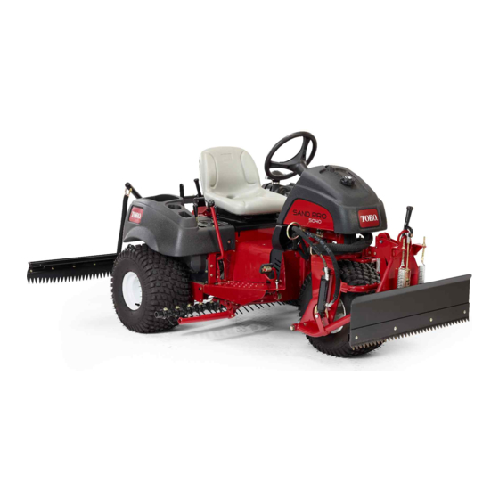
Front Lift Frame
Sand Pro
Model No. 08712-Serial No. 311000336 and Up
This product complies with all relevant European directives. For details, please see the Declaration of
Incorporation (DOI) at the back of this publication.
Note:
Determine the left and right sides of the machine from the normal operating position.
Setup
Loose Parts
Use the chart below to verify that all parts have been shipped.
Procedure
1
2
3
4
5
6
© 2021-The Toro® Company
8111 Lyndale Avenue South
Bloomington, MN 55420
®
/Infield Pro
Description
No parts required
No parts required
Straight hydraulic fitting with O-ring
90° hydraulic fitting with O-ring
Lift valve
Valve plate
Bolt (1/4 x 3 inches)
Locknut (1/4 inch)
Bolt (#10 x 1-1/4 inches)
Locknut (#10)
Lift lever
Register at www.Toro.com.
®
5040 Traction Unit
Qty.
-
-
-
2
2
1
1
3
3
2
2
1
2
2
1
1
3
3
2
2
1
1
1
4
4
1
2
Original Instructions (EN)
Form No. 3448-319 Rev A
Operator's Manual
Use
Prepare the machine.
Remove the shrouds.
Install the lift valve (Model 08705).
Install the lift valve (Model 08745).
Install the plow plates.
*3448-319*
Printed in the USA
All Rights Reserved
Advertisement
Table of Contents

Related Manuals for Toro Sand Pro 5040


Summary of Contents for Toro Sand Pro 5040
-
Page 1: Table Of Contents
Bolt (1/2 x 2 inches) Install the plow plates. Locknut (1/2 inch) Hitch frame bracket Bolt (1/2 x 1-3/4 inches) *3448-319* © 2021—The Toro® Company Original Instructions (EN) Register at www.Toro.com. 8111 Lyndale Avenue South Printed in the USA Bloomington, MN 55420... - Page 2 Procedure Description Qty. Hitch frame Bolt (3/8 x 2 inches) Nut (3/8 inch) Capscrew (3/8 x 1-1/2 inches) Locknut (3/8 inch) Cylinder pin Adapter plate Push arm tube Install the push arms and hitch frame. Pin assembly Thread-forming screw Bolt (5/8 x 1-1/2 inches) Washer (1.68-inch outside diameter x 0.65-inch inside diameter) Tube...
- Page 3 Preparing the Machine No Parts Required Procedure Park the machine on a level surface. Lower the attachments. Engage the parking brake. Shut off the engine and remove the key. g003660 Figure 1 1. Control panel 3. Console mounting bolt locations 2.
-
Page 4: No Parts Required
g003671 Figure 4 1. Oil cooler 2. Hydraulic tube Secure the remaining hydraulic tube to the g003662 frame with the clamp and fasteners previously Figure 3 removed. 1. Center shroud Preparing to Install the Hydraulic Components No Parts Required Procedure Locate the hydraulic tube that goes from the oil cooler to the existing lift valve (Figure... - Page 5 If you are installing this kit to a Model 08745 machine, do the following: Remove the 3 bolts and nuts securing the existing lift valve to the frame, and separate it from the frame to allow for removal of the T-fitting (340-94) as shown in Figure Disconnect the hydraulic tube (108-8415)
-
Page 6: Straight Hydraulic Fitting With O-Ring
Note: The valve installation is very similar to the existing valve that is already installed. Loosely mount the pivot lever assembly to the valve spool and to the offset link with 2 bolts Installing the Lift Valve (#10 x 1-1/4 inch) and 2 locknuts (Figure Note: Do not tighten the fasteners at this time. - Page 7 existing valve in 3 Preparing to Install the Hydraulic Components (page 4) into the new lift valve as shown in Figure Mount the valve assembly, pivot bracket, and Installing the Lift Valve valve plate to the frame with 3 bolts (1/4 x 3 inches) and 3 locknuts (Figure 10).
-
Page 8: Right Plow Plate
Installing the Plow Plates Parts needed for this procedure: Right plow plate Left plow plate Bolt (1/2 x 2 inches) g003665 Figure 11 Locknut (1/2 inch) 1. Right plow plate 3. Steering pivot Hitch frame bracket 2. Left plow plate 4. - Page 9 pin assemblies to the adapter plates with 2 Mount the hitch frame tubes to the plow plates thread-forming screws. with bolts (3/8 x 1-1/2 inches) and nuts (Figure 14), and tighten the fasteners. Note: Position the components as shown in Figure g003787 Figure 12...
- Page 10 g028340 Figure 16 Important: Ensure that the existing hoses are routed above the guide, as shown in Figure g003669 Figure 17 1. Hydraulic cylinder 3. 45° fitting 2. 90° fitting 4. Plug (1/8 inch) Mount the top of the hydraulic cylinder barrel Installing the Hydraulic to the pin on the right-hand plow plate with a retaining ring...
- Page 11 Connect the 45° fitting end of hydraulic hose (Part No. 108-8449) to the 90° fitting on the right side of the valve and the straight end of the hose to the vacant oil cooler fitting (Figure 19). Refer Figure 20 Figure 21 for hose routing.
- Page 12 g218466 Figure 20 Model 08705 1. Cable tie 2. Hydraulic hose (Part No. 3. Hydraulic hose (Part No. 4. Hydraulic hose (Part No. 108-8449) 108-8453) 108-8454)
- Page 13 g218467 Figure 21 Model 08705 1. Cable tie 3. Hydraulic hose (Part No. 108-8453) 2. Hydraulic hose (Part No. 108-8449) 4. Hydraulic hose (Part No. 108-8454)
- Page 14 Important: Ensure that the hoses are routed away from any sharp, hot, or moving components. Tighten all fasteners and fittings. Installing the Hydraulic Using cable ties, secure the hoses to the machine at the locations shown in Figure 23 Hoses Figure Model 08745 Only Parts needed for this procedure:...
- Page 15 g362578 Figure 22 Model 08745 1. New valve 3. Existing valve 5. Wire hose holder 7. Hydraulic hose (Part No. 108-8454) 2. Tube assembly (Part No. 4. Hydraulic hose (Part No. 6. Hydraulic hose (Part No. 108-8447) 108-8449) 108-8453)
- Page 16 g218466 Figure 23 Model 08745 1. Cable tie 2. Hydraulic hose (Part No. 3. Hydraulic hose (Part No. 4. Hydraulic hose (Part No. 108-8449) 108-8453) 108-8454)
- Page 17 g362591 Figure 24 Model 08745 1. Cable tie 2. Hydraulic hose (Part No. 3. Hydraulic hose (Part No. 4. Hydraulic hose (Part No. 108-8449) 108-8453) 108-8454)
- Page 18 WARNING Hydraulic fluid escaping under pressure can penetrate skin and cause injury. Installing the Control Panel • If hydraulic fluid is injected into the skin it must be surgically removed and Lever Guide Plate within a few hours by a doctor familiar with this type of injury.
- Page 19 Tighten both lift lever guide plate mounting screws to secure the adjustment (Figure 25). Remove the hour meter from the old control panel and install it in the new control panel. Reading/Storing the Install the new control panel and plug the wire into the hour meter.
- Page 20 The front lift frame has 5 grease fittings (Figure that must be lubricated regularly with No. 2 lithium A selection of Toro approved attachments and grease. If the machine is operated under normal accessories is available for use with the machine to conditions, lubricate all bearings and bushings after enhance and expand its capabilities.
- Page 21 Notes:...
- Page 22 The method of transmission shall be electronic transmittal. This machinery shall not be put into service until incorporated into approved Toro models as indicated on the associated Declaration of Conformity and in accordance with all instructions, whereby it can be declared in conformity with all relevant Directives.
- Page 23 The Toro Company (“Toro”) respects your privacy. When you purchase our products, we may collect certain personal information about you, either directly from you or through your local Toro company or dealer. Toro uses this information to fulfil contractual obligations - such as to register your warranty, process your warranty claim or to contact you in the event of a product recall - and for legitimate business purposes - such as to gauge customer satisfaction, improve our products or provide you with product information which may be of interest.
- Page 24 Countries Other than the United States or Canada Customers who have purchased Toro products exported from the United States or Canada should contact their Toro Distributor (Dealer) to obtain guarantee policies for your country, province, or state. If for any reason you are dissatisfied with your Distributor's service or have difficulty obtaining guarantee information, contact your Authorized Toro Service Center.