Table of Contents
Advertisement
Quick Links
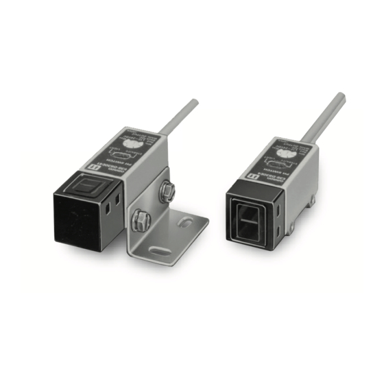
Photoelectric Sensor with Built-in Amplifier
E3S
General-purpose Photoelectric
Sensor for High Quality and Reliable
Detection
Be sure to read Safety Precautions
on page 8.
Ordering Information
General-purpose Sensors
Sensing method
Appearance
Convergent-reflective
(narrow vision field)
Convergent-reflective
(wide vision field)
Through-beam
Retro-reflective
Diffuse-reflective
Through-beam
Retro-reflective
Diffuse-reflective
* Production was discontinued.
Note: E3S-2/-5/-DS10/-DS30/-R2 in this catalog have been discontinued at the end of March 2014.
Sensing distance
Operation mode
30 to 100 mm (variable)
50 to 250 mm (variable)
2 m
5 m
0.1 to 2 m
Light-ON/Dark-ON
100 mm
(selectable)
300 mm
2 m
5 m
0.1 to 2 m
100 mm
300 mm
CSM_E3S_DS_E_13_1
Model
E3S-LS10XE4 2M
E3S-LS20XE4 2M
E3S-2E4
*
Emitter
E3S-2LE4
*
Receiver E3S-2DE4
*
E3S-5E4
*
Emitter
E3S-5LE4
*
Receiver E3S-5DE4
*
E3S-R2E4
*
E3S-DS10E4
*
E3S-DS30E4
*
E3S-2E41
*
Emitter
E3S-2LE41
*
Receiver E3S-2DE41
*
E3S-5E41
*
Emitter
E3S-5LE41
*
Receiver E3S-5DE41
*
E3S-R2E41
*
E3S-DS10E41
*
E3S-DS30E41
*
1
Advertisement
Table of Contents

Related Manuals for Omron E3S-LS10XE4 2M


Summary of Contents for Omron E3S-LS10XE4 2M
- Page 1 8. Ordering Information General-purpose Sensors Sensing method Appearance Sensing distance Operation mode Model Convergent-reflective E3S-LS10XE4 2M 30 to 100 mm (variable) (narrow vision field) Convergent-reflective E3S-LS20XE4 2M 50 to 250 mm (variable) (wide vision field) E3S-2E4 Emitter E3S-2LE4...
- Page 2 Ratings and Specifications Retro-re- Sensing method Through-beam Diffuse-reflective Convergent-reflective flective E3S- E3S-2E4 E3S-5E4 E3S-R2E4 DS10E4 E3S- E3S- E3S- E3S- Model E3S-2E41 E3S-5E41 E3S-R2E41 E3S- DS30E41 DS30E4S LS10XE4 LS20XE4 Item DS10E41 30 to 100 mm 50 to 250 mm 100 mm 300 mm Continuously Continuously...
- Page 3 Engineering Data (Reference Value) Parallel Operating Range E3S-2E4 (41) E3S-5E4 (41) E3S-2E41 E3S-2E4 Parallel movement Parallel movement distance Y distance Y Distance X Distance X Distance X (m) Distance X (m) Operating Range E3S-DS10E4 (41) E3S-DS30E4 (41) Optical axis Optical axis (−Y) Operating Operating...
- Page 4 Sensing Distance vs. Size of Sensing Object Parallel Operating Range E3S-DS30E4 (41) E3S-R2E4 (41) (42) E3S-DS10E4 (41) E3S-LS20XE4 The larger the sensing object, the longer the operating distance. E3S-DS30E4 (1) White paper Short edge Sensing object E3S-DS10E4 (1) White Long paper edge Parallel movement...
- Page 5 I/O Circuit Diagrams Item Opera- tion Output circuit Timing charts Wire Power mode Model color polarity 12 to 24 VDC Brown *1 Stability Light indicator Incident light indicator (green) Load 1 (red) Brown No incident light (relay) Light 1.5 to Photo- indicator Black...
- Page 6 Connection ● With Relay Load Through-beam Sensors Retro-reflective Sensors Light Interrupted and Load Operating for E3S-2E4 (41) Light Interrupted and Load Operating for E3S-R2E4 (41) and -5E4 (41) (42), -DS10E4(41), and -DS30E4 (41) Blue Load 80 mA max. Brown 12 to 24 V Black Pink 80 mA max.
- Page 7 Adjustment Methods ● Adjusting the E3S-LS10XE4 Convergent-reflective ● Adjusting the E3S-LS20XE4 Convergent-reflective Sensor Sensor Adjustment Method 1 Sensitivity adjustment Use this method if the sensing object is more reflective than the background. E3S-LS10XE4 Distance adjustment scale Sensing object Distance adjuster Distance adjuster Background Align the distance adjustment scale...
- Page 8 Safety Precautions Be sure to read the precautions for all models in the website at: http://www.ia.omron.com/. Warning Indications Precautions for Correct Use Warning level 1. Do not use the product in any atmosphere or environment Indicates a potentially hazardous situation which, WARNING that exceeds the ratings.
- Page 9 ● Sensors with Open-collector Outputs ● Sensors with Different Orientations Sensors with Open-collector Outputs The E3S-5, E3S-DS30, and E3S-R2 that sense in different directions can be made. Rated Output Output Output Switching Type current protection Sensing type transistor current output circuit Sensing direction method...
-
Page 10: Table Of Contents
(Unit: mm) Dimensions Unless otherwise specified, the tolerance class IT16 is used for dimensions in this data sheet. General-purpose Sensors E3S-2E4 E3S-2E41 4-dia. vinyl-insulated round cable with 2/3 conductors 4-dia. vinyl-insulated round cable with 2/3 conductors (Conductor cross section: 0.2 mm , Insulator diameter: 1.1 mm), (Conductor cross section: 0.2 mm Standard length: 2 m... -
Page 11: Two, M3
E3S-DS10E4 E3S-DS10E41 4-dia. vinyl-insulated round cable with 3 conductors (Conductor cross section: 0.2 mm , Insulator diameter: 1.1 mm), 4-dia. vinyl-insulated round cable with 3 conductors Standard length: 2 m (Conductor cross section: 0.2 mm , Insulator diameter: 1.1 mm), Weight: Approx. -
Page 12: Sensitivity Adjuster
E3S-R2E42 E3S-LS10XE4 E3S-LS20XE4 4-dia. vinyl-insulated round cable with 3 conductors (Conductor cross section: 0.2 mm , Insulator diameter: 1.1 mm), Standard length: 2 m 4-dia. vinyl-insulated round cable with 3 conductors Weight: Approx. 225 g (Conductor cross section: 0.2 mm , Insulator diameter: 1.1 mm), Standard length: 2 m 2.1R... - Page 13 Accessories (Order Separately) Special Mounting Bracket E39-L2 92.1 82.1 Mounting Holes Two, M4 10.2 20.2 25.4 25.4 Two, M4 slotted Applicable models: E3S-5E41 hexagonal bolts E3S-R2E41 E3S-DS30E41 2.1R 25.4 29.1 E39-L4 68.5 60.8 Mounting Holes Two, M3 15.70 Two, M3 Applicable models: E3S-2E41 28.5...
- Page 14 Slit (Order Separately) Slit E39-S2 10.5 E39-S2 Applicable E3S-2E4 Sensors E3S-2E41 17.8 Note 1. Three sets of slits are provided: 6.5 x 0.5 mm, 6.5 x 1 mm and 6.5 x 17.9 2 mm (16.7) 2. One set consists of two slits, one each for the Emitter and Receiver.
- Page 15 (a) Exclusive Warranty. Omron’s exclusive warranty is that the Products will be free from defects in materials and workmanship for a period of twelve months from the date of sale by Omron (or such other period expressed in writing by Omron). Omron disclaims all other warranties, express or implied.