Advertisement
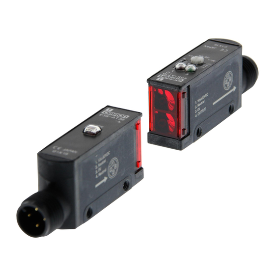
Built-in Amplifier Photoelectric Sensor
E3S-A
Ordering Information
E3S-A General-purpose Sensors
Connections
Appearance
Prewired
Horizontal
E3S-A
Sensing
Sensing
method
distance
Through-beam 7 m
Retroreflective
0.1 to 2 m
(polarized)
Diffuse reflec-
10 cm (light
tive
source: infra-
red)
20 cm
70 cm (light
source: infra-
red)
Operating
Output / timer
modes
functions
Light-ON
---
Dark-ON
With timer and
(selectable)
self-diagnostic
functions
---
With timer and
self-diagnostic
functions
---
With timer and
self-diagnostic
functions
---
With timer and
self-diagnostic
functions
---
With timer and
self-diagnostic
functions
Model
NPN output
PNP output
E3S-AT11
E3S-AT31
E3S-AT21
E3S-AT41
E3S-AR11
E3S-AR31
E3S-AR21
E3S-AR41
E3S-AD13
E3S-AD33
E3S-AD23
E3S-AD43
E3S-AD11
E3S-AD31
E3S-AD21
E3S-AD41
E3S-AD12
E3S-AD32
E3S-AD22
E3S-AD42
A-231
Advertisement
Table of Contents

Related Manuals for Omron E3S-A


Summary of Contents for Omron E3S-A
-
Page 1: Ordering Information
Built-in Amplifier Photoelectric Sensor E3S-A Ordering Information E3S-A General-purpose Sensors Connections Appearance Sensing Sensing Operating Output / timer Model method distance modes functions NPN output PNP output Prewired Horizontal Through-beam 7 m Light-ON E3S-AT11 E3S-AT31 Dark-ON With timer and E3S-AT21... - Page 2 Model Remarks Slit for Through-beam Sensor E39-S46 2 mm, 1 mm, and 0.5 mm slits are sold in pairs, one each for the receiver and emitter of a through-beam model Mounting Bracket for Vertical Sensor E39-L59 Purchase two brackets for each through-beam model...
-
Page 3: Specifications
Open collector current output (NPN or PNP) Circuit protection Load short-circuit protection, reverse connection protection, mutual interference prevention (except for through-beam models) Indicators Light indicator (red) and stability indicator (green); emittion indicator (red) for the emitter of through-beam models Materials Case: Polybutylene terephtalate... - Page 4 Open collector current output (NPN or PNP) Circuit protection Load short-circuit protection, reverse connection protection, mutual interference prevention (except for through-beam models) functions Indicators Light indicator (red) and stability indicator (green); emittion indicator (red) for the emitter of the through-beam model Materials Case: Polybutylene terephtalate...
- Page 5 Control output 30 VDC, 100 mA max. (residual voltage: 1 V max.) Open collector (residual voltage: 0.4 V max. at 16 mA) Self-diagnostic output Only Sensors with self-diagnostic function: 50 mA max, 30 VDC (residual voltage: 1 V max.), open collector (re- sidual voltage: 0.4 V max.
-
Page 6: Engineering Data
Distance X (m) X (cm) X (cm) E3S-AD@2 E3S-AD@2 E3S-AD@3/@8 E3S-AD@3/@8 Sensing Distance vs. Object Size Excess Gain vs. Set Distance E3S-AD@ E3S-AT@1 (Typical) E3S-AD@1, -AD@2, -AD@3, -AD@8 (Detection of White Paper) Sensing object: white (E3S-AD@2: 20 x 20 cm... -
Page 7: Operation
Operation Output Circuits Type Model Mode switch Output transistor Output circuit E3S-AT11 Light ON ON when light is re- Emitter Emission E3S-AT16 ceived Brown E3S-AT11/AT16/ (Red) E3S-AT61 AT61/AT66 10 to Main E3S-AT66 30 VDC circuit E3S-AR11 Blue E3S-AR16 E3S-AR61 E3S-AR66... - Page 8 Type Model Mode switch Output transistor Output circuit E3S-AT31 Light ON ON when light is re- Emitter E3S-AT36 ceived E3S-AT31/AT36/ Brown Emission (Red) E3S-AT81 AT81/AT86 Main E3S-AT86 10 to circuit 30 VDC E3S-AR31 Blue E3S-AR36 E3S-AR81 E3S-AR86 Brown E3S-AD33 Stability...
-
Page 9: Timing Charts
Timing Charts Type Model Mode switch Output transistor Timing chart E3S-AT11 Light ON ON when light is re- E3S-AT16 ceived. E3S-AT61 Light received Light not received E3S-AT66 Light indicator E3S-AR11 (Red) E3S-AR16 Output transistor E3S-AR61 Load Operate E3S-AR66 (Between brown and black) - Page 10 Type Model Mode switch Output transistor Timing chart E3S-AT31 Light ON ON when light is re- E3S-AT36 ceived. Light received E3S-AT81 Light not received E3S-AT86 Light indicator E3S-AR31 (Red) E3S-AR36 Output transistor E3S-AR81 (Between blue and black) Load Operate E3S-AR86...
-
Page 11: Self-Diagnostic Function
Self-diagnostic Function With this function, the E3S-A checks changes in environmental conditions (especially a change in the ambient temperature) and self-diagnoses the resistance against the changes. The result is shown by the indicators or an output signal. Amount of Green indicator... - Page 12 There is no need to adjust the sensitivity of each photoelectric sensor in- dividually.
-
Page 13: Operating Mode Selection
3 mins.) Operating Mode Selection As shown in the following illustration, the E3S-A has an oper- ating mode selector on the panel where the Receiver connec- tor is located. With this operating mode selector, the E3S-A is in either dark-ON or light-ON mode. - Page 14 16.2 10.7 A (see note) A (see note) Two, M3 x 12 screws Note: The mounting bracket can be attached to side A. E3S-AT11, E3S-AT31 (Emitter) Light indicator (red) Polyvinyl chloride-covered cord , 4-mm dia. (0.12-mm x 18), 2 cores, 17.8...
- Page 15 16.2 1.2 10.7 A (see note) A (see note) Two, M3 x 12 screws Note: The mounting bracket can be attached to side A. E3S-AT21, E3S-AT41 Turbo Switch (Emitter) Light indicator (red) Polyvinyl chloride-covered cord, 4-mm dia. (0.12-mm x 18), 2 cores, 12.9...
- Page 16 11.5 19.7 10.7 Emitter A (see note) A (see note) Two, M3 x 12 screws Note: The mounting bracket can be attached to side A. E3S-AD11, E3S-AD31 E3S-AD13, E3S-AD31 Sensitivity adjustor Light indicator (red) (white) E3S-AD12, E3S-AD32 Polyvinyl chloride-covered cord, 4-mm dia.
- Page 17 29.2 19.7 Emitter 10.7 A (see note) A (see note) Two, M3 x 12 screws Note: The mounting bracket can be attached to side A. E3S-AT61, E3S-AT81 (Receiver) Lens (7 x 7) Optical axis Polyvinyl chloride-covered cord, 13.5 4-mm dia. (0.12-mm x 18), 4 cores, Standard length: 2 m 12.4 12...
- Page 18 A (see note) 10.7 A (see note) 10.5 20+0.2 Two, M3 x 12 screws Note: The mounting bracket can be attached to side A. E3S-AT71, E3S-AT91 (Receiver) Lens (7 x 7) Optical axis Polyvinyl chloride-covered cord, 13.5 4-mm dia. (0.12-mm x 18), 4 cores, Standard length: 2 m 12.4 12...
- Page 19 29.2 A (see note) 10.7 A (see note) 10.5 20+0.2 Two, M3 x 12 screws Note: The mounting bracket can be attached to side A. E3S-AR61, E3S-AR81 Receiver Optical axis E3S-AR71, E3S-AR91 Emitter Lens (7 x 14) (4) (see note 2) Polyvinyl chloride-covered cord, 13.5...
- Page 20 Sensitivity adjustor (white) 29.2 10.7 A (see note) A (see note) 10.5 Two, M3 x 12 screws 20+0.2 Note: The mounting bracket can be attached to side A. E3S-AD71, E3S-AD91 E3S-AD73, E3S-AD93 Receiver Optical axis E3S-AD72, E3S-AD92 Emitter Lens (7 x 14) Polyvinyl chloride-covered cord, 4-mm dia.
- Page 21 Lens (7 x 7) Light-ON Dark-ON 29.2 16.2 1.2 10.7 A (see note) A (see note) Two, M3 x 12 screws Note: The mounting bracket can be attached to side A. E3S-AT16, E3S-AT36 (Emitter) Light indicator (red) Connector M12 (10) 17.8 12.4 16.9 10.7...
- Page 22 11.5 19.8 1.2 10.7 A (see note) Emitter A (see note) Two, M3 x 12 screws Note: The mounting bracket can be attached to side A. E3S-AD16, E3S-AD36 Connector M12 E3S-AD18, E3S-AD38 Light indicator (red) Sensitivity adjustor (white) E3S-AD17, E3S-AD37 (10) 12.9...
- Page 23 Spacer (attachment) 10.5 (Attach the spacer or 20+0.2 Two, M3 x 12 screws the plug cannot be connected.) Note: The mounting bracket can be attached to side A. E3S-AT66, E3S-AT86 (Emitter) Lens (7 x 7) Optical axis Connector M12 (10) 13.5...
- Page 24 10.7 Spacer (attachment) (Attach the spacer or 10.5 20+0.2 the plug cannot be connected.) Two, M3 x 12 screws Note: The mounting bracket can be attached to side A. E3S-AD66, E3S-AD86 Receiver E3S-AD68, E3S-AD88 Optical axis E3S-AD67, E3S-AD87 Connector M12...
- Page 25 Accessories Plug (for E3S-A Connector type) The XS2F-D421 Straight Cable Connector is also available. Straight Type Refer to the output circuit diagram on page A-237. XS2F-D421-DC0-A Cable No. of Cord Model drawing conductors length direction Straight XS2F-D421-DC0-A Polyvinyl chloride-cov- XS2F-D421-D80-A ered cord, 0.5 mm...
- Page 26 Retroreflector (Included with E3S-@R@@) 40.3 E39-R1 Two, 3.5 dia. holes (62.1) 59.9 52 A-256 Standard Photoelectric Sensors...
- Page 27 Accessories (Order Separately) Vertical Mounting Bracket (for E3S-A) E39-L59 18 11 34.5 63.8 10.5 (74.3) Mounting Example of E3S-A on E39-L59 10.5 57.3 74.3 Two mounting holes 15.7 Mounting bracket (E39-L59) 3.2 6.2 18 10.5 Two, M3 x 12 screws 34.5...
- Page 28 Stainless steel (SUS304) 13.6 21.4 11.1 (See note) Note: Two vertical filters and two horizontal filters are Note: The width of A is 0.5 mm, 1 mm, or sold together. 2 mm depending on the model. A-258 Standard Photoelectric Sensors...
- Page 29 Mini-reflector E39-R4 Optical Axis Confirmation Reflector (for E3S-A) E39-R5 Bracket to be at 15.9 tached to the emitter panel of E3S-A 11.7 11.6 13.7 9.7+0.1 11.2 59.9 25 23 19+0.1 Two, 2.2 dia. 40.9 Small Reflector E39-R3 Adhesive tape 34.8 25.4...
- Page 30 E39-R3 - With Enclosed Mounting Bracket 145 13.7 18.45 22.9 Two, 3.2 dia. holes Two, M3 25.4+0.1 R25.4 41.8 10.1 1.2 Reflecting Tape E39-RS1 Adhesive tape Reflecting Tape E39-RS2 Adhesive tape A-260 Standard Photoelectric Sensors...
-
Page 31: Installation
Blue 10 to 30 V for the E3S-A ** If the load is a relay, insert a surge absorbing diode between the coils of the relay. *** The connection examples are for sensors with the NPN output. With Sensor Controller S3D2... - Page 32 Color of cord Connection Application pin No. Turn part B by hand (do not use a pliers or the plug will be For DC Brown Power supply (+V) damaged) and tighten it with part C so that length A is nearly...
-
Page 33: Installation Of Accessories
Mounting Bracket Note: Apply the slit to the lens of the photoelectric sensor marked with an arrow indicating the position of the optical axis (apply it to the bottom lens of hor- The direction of the optical axis coincides with the mounting izontal sensors and the top lens of vertical sensors). - Page 34 ALL DIMENSIONS SHOWN ARE IN MILLIMETERS. To convert millimeters into inches, multiply by 0.03937. To convert grams into ounces, multiply by 0.03527. In the interest of product improvement, specifications are subject to change without notice. Cat. No.E220-E2-04-X A-264 Standard Photoelectric Sensors...