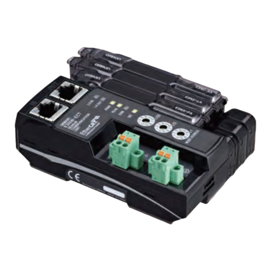
Omron E3NW-ECT Operation Manual
Ethercat
digital sensor communication unit
Hide thumbs
Also See for E3NW-ECT:
- Connection manual (36 pages) ,
- Manual (3 pages) ,
- Operation manual (174 pages)
Table of Contents
Advertisement
Quick Links
Advertisement
Chapters
Table of Contents

Related Manuals for Omron E3NW-ECT


Summary of Contents for Omron E3NW-ECT
- Page 1 E3NW-ECT EtherCAT ® Digital Sensor Communication Unit Operation Manual E429-E1-07...
- Page 2 OMRON. No patent liability is assumed with respect to the use of the information contained herein. Moreover, because OMRON is constantly striving to improve its high-quality products, the information contained in this manual is subject to change without notice.
- Page 3 E3NW-ECT EtherCAT Digital Sensor Communication Unit Operation Manual Revised December 2017...
- Page 5 Thank you for purchasing a E3NW-ECT EtherCAT Digital Sensor Communication Unit. This manual contains information you need to know to use the E3NW-ECT. Before use, please make sure that you thoroughly read the manual and have a full understanding of the products functions and performance.
-
Page 6: How To Read The Manual
Specification Applicable wire range Spring AWG28 (0.08mm ) to AWG20 (0.5mm XN2A-1430 clamp type Sheath diameter: 1.5 mm max. Name of manuals GX-series EtherCAT Slave Unit User’s Manual 4 - 11 E3NW-ECT EtherCAT Digital Sensor Communication Unit Operation Manual (E429) - Page 7 Precautions for Correct Use Indicates precautions on what to do and what not to do to ensure proper operation and performance. Reference This explains useful tips and reference information when using the product. E3NW-ECT EtherCAT Digital Sensor Communication Unit Operation Manual (E429)
- Page 8 The appendices give an overview of the objects and Appendices Appendices precautions on their use, and describes the specifications of the E3NW-DS Distributed Sensor Unit. E3NW-ECT EtherCAT Digital Sensor Communication Unit Operation Manual (E429)
- Page 9 Omron’s exclusive warranty is that the Products will be free from defects in materials and workman- ship for a period of twelve months from the date of sale by Omron (or such other period expressed in writing by Omron). Omron disclaims all other warranties, express or implied.
- Page 10 Disclaimers Performance Data Data presented in Omron Company websites, catalogs and other materials is provided as a guide for the user in determining suitability and does not constitute a warranty. It may represent the result of Omron’s test conditions, and the user must correlate it to actual application requirements. Actual perfor- mance is subject to the Omron’s Warranty and Limitations of Liability.
-
Page 11: Safety Precautions
This symbol means it is a compulsory item (an item that must be done). The specific instruction is indicated using text inside the The symbol shown to the left indicates "typical compulsory items". E3NW-ECT EtherCAT Digital Sensor Communication Unit Operation Manual (E429) - Page 12 Implement proper measures as part of your communications system or in your program to ensure safety in the system even when a communications error or malfunction occurs during remote I/O communication. E3NW-ECT EtherCAT Digital Sensor Communication Unit Operation Manual (E429)
- Page 13 Fail-safe measures must be taken by the customer to ensure safety in the event of incorrect, missing, or abnormal signals caused by broken signal lines, momentary power interruptions, or other causes. Not doing so may result in serious accidents. E3NW-ECT EtherCAT Digital Sensor Communication Unit Operation Manual (E429)
-
Page 14: Power Supply
• Turn OFF the power of PLC and all the Slave Units before wiring the communication cables. • Do not apply voltages to the Input Slave Units in excess of the rated input voltage. Excess voltage or loads may result in burning. E3NW-ECT EtherCAT Digital Sensor Communication Unit Operation Manual (E429) - Page 15 External Circuits • Install external breakers and take other safety measures against short-circuiting in external wiring. Applicable standards • EN61326-1 • Electromagnetic environment : Industrial electromagnetic environment (EN/IEC 61326-1 Table 2) E3NW-ECT EtherCAT Digital Sensor Communication Unit Operation Manual (E429)
- Page 16 • Locations subject to possible exposure to radioactivity. • Locations close to power supplies. • Do not drop any Unit or subject any Unit to excessive shock or vibration. Otherwise, Unit failure or malfunction may occur. E3NW-ECT EtherCAT Digital Sensor Communication Unit Operation Manual (E429)
- Page 17 OMRON devices that comply with EC Directives will vary depending on the configuration, wiring, and other conditions of the equipment or control panel on which the OMRON devices are installed. The customer must, therefore, perform the final check to confirm that devices and the overall machine conform to EMC standards.
-
Page 18: Related Manuals
Hardware User’s Manual (Cat. No. W500) and the Manual NJ-series CPU Unit Software User’s Manual (Cat. No. W501). Sysmac Studio Version 1 W504 Explains the operating procedures of the Sysmac Studio. Operation Manual E3NW-ECT EtherCAT Digital Sensor Communication Unit Operation Manual (E429) -
Page 19: Table Of Contents
Overview of Configuration Devices ........1-7 1 - 1 E3NW-ECT EtherCAT Digital Sensor Communication Unit Operation Manual (E429) -
Page 20: Overview Of Ethercat Networks
With this structure, EtherCAT secures high-speed and real-time data transmission. Slave Unit Slave Unit Slave Unit EtherCAT Master Unit Data • Reading output data addressed to the local Slave Units • Writing input data Ethernet frame 1 - 2 E3NW-ECT EtherCAT Digital Sensor Communication Unit Operation Manual (E429) - Page 21 1...n EtherCAT telegram EtherCAT frame EtherCAT header 1st EtherCAT 2nd EtherCAT ..n th EtherCAT telegram telegram telegram Telegram Data header WKC : Working counter 1 - 3 E3NW-ECT EtherCAT Digital Sensor Communication Unit Operation Manual (E429)
-
Page 22: Communications Types Of Ethercat
EtherCAT Master Unit. It performs the following data communications: • Read and write process data • Make Slave Unit setting • Monitor Slave Unit state 1 - 4 E3NW-ECT EtherCAT Digital Sensor Communication Unit Operation Manual (E429) -
Page 23: Connection Examples Of Ethercat
Connection Examples of EtherCAT This section explains the connection examples of EtherCAT network. EtherCAT Master Unit DC24V Digital I/O Slave Unit Servo Drive Servomotor Inverter E3NW-ECT EtherCAT Sensor Communications Unit 1 - 5 E3NW-ECT EtherCAT Digital Sensor Communication Unit Operation Manual (E429) -
Page 24: Configuration Elements Of Ethercat Network
Peripheral port connection ESI file I/O power supply Communications cable Unit power supply Analog I/O Slave Unit Digital I/O Slave Unit E3NW-ECT EtherCAT Sensor Communications Unit Servo Drive Inverter 1 - 6 E3NW-ECT EtherCAT Digital Sensor Communication Unit Operation Manual (E429) -
Page 25: Overview Of Configuration Devices
Provides power for input/output operations of external devices connected to Slave Units. Separate from Unit power supply when wiring. The E3NW-ECT does not require an I/O power supply. 1 - 7 E3NW-ECT EtherCAT Digital Sensor Communication Unit Operation Manual (E429) - Page 26 1 EtherCAT Network 1 - 8 E3NW-ECT EtherCAT Digital Sensor Communication Unit Operation Manual (E429)
- Page 27 2-1 Overview of E3NW-ECT ........
-
Page 28: Overview Of E3Nw-Ect
NJ-series Controller, other Machine Automation Controllers, and the Sysmac Studio Automation Software to achieve optimum functionality and ease of operation. * “Sysmac devices” is a generic name for EtherCAT Sensor Communication Units and other OMRON control components that were designed with the same communications and user interface specifications. -
Page 29: Connectable Sensor Amplifiers
E9NC-VA□0 Voltage (1 to 5 V) Input Amplifier * The E9NC-TA0 is supported from E3NW-ECT Ver 1.03. The E3NX-CA0 is supported from E3NW-ECT Ver 1.06. The E3NX-MA0, E2NC-EA□0, E9NC-AA□0 / VA□0 are supported from E3NW-ECT Ver 1.08 of the E3NW-ECT. - Page 30 2 EtherCAT Sensor Communication Unit 2 - 4 E3NW-ECT EtherCAT Digital Sensor Communication Unit Operation Manual (E429)
- Page 31 Setting Slave Unit Parameter ........3-6 3 - 1 E3NW-ECT EtherCAT Digital Sensor Communication Unit Operation Manual (E429)
-
Page 32: Setup Examples And Basic Procedure
Although it is not shown in the figure above, supply the unit power and the I/O power separately. Reference The setting example explained here is the basic setting of E3NW-ECT EtherCAT Sensor Communication Units. If more detailed settings are required in actual operation, refer to the manual of the EtherCAT Master Unit. -
Page 33: Basic Procedure
Section 3-3-2 Setting an EtherCAT Communications Section 3-3-3 Starting EtherCAT Communications Checking Unit Displays Section 3-4-1 Section 3-4-2 Confirming Data Read and Write Section 3-4-3 Setting Slave Unit Parameter 3 - 3 E3NW-ECT EtherCAT Digital Sensor Communication Unit Operation Manual (E429) -
Page 34: Setting And Wiring Hardware
Mount each slave and Distributed Sensor Unit in their designated locations, and then set the node addresses and other settings. For details, refer to each item below. Mounting "4-1 Mounting E3NW-ECT and Sensor Amplifiers" on page 4-2 Setting Hardware "6-3-2 Node Address Setting Switches" on page 6-6 Set the node address. -
Page 35: Starting Communications
Configuration Tool. The maximum assignable PDO size for the E3NW-ECT is 350 bytes. (Refer to "7-2-3 Mode Setting Functions for PDO Communications" on page 7-6 for details.) Do not assign PDOs that exceed the maximum assignable PDO size. -
Page 36: Checking Operations
Always set the following objects in your initial settings for the E3NW-ECT. • If you intend to use a Dummy Sensor, make sure to register the Dummy Sensor. 3 - 6 E3NW-ECT EtherCAT Digital Sensor Communication Unit Operation Manual (E429) - Page 37 This chapter explains the mounting and wiring methods of the EtherCAT Slave Unit. 4-1 Mounting E3NW-ECT and Sensor Amplifiers ..... . . 4-2 4-1-1 Mounting Method .
-
Page 38: Mounting E3Nw-Ect And Sensor Amplifiers
4 Installation and Wiring Mounting E3NW-ECT and Sensor Amplifiers This section describes how to mount and remove the E3NW-ECT and individual Amplifiers to the DIN Track. 4-1-1 Mounting Method Use the following procedure to mount the Units. 1. Hook the upper portion of the Unit on the DIN Track. -
Page 39: Removal Method
Perform step 1 and Do not perform step then step 2. 2 before step 1. After you finish these steps, make sure the E3NW-ECT is securely in place. 4-1-2 Removal Method Use the following procedure to remove the Units. 1. Slide the Sensor Amplifier Units away and remove the Sensor Communication Unit first. -
Page 40: Connecting To Ethercat Network
• Use the cables in locations without powder dust and oil mist. • There is a limit to the bending radius of communications cables. Check the specification of communications cables to be used for the information on bending radius. 4 - 4 E3NW-ECT EtherCAT Digital Sensor Communication Unit Operation Manual (E429) -
Page 41: Preparation For Connecting Network
• Sizes and Conductor Pairs: AWG 22 × 2 Pairs Part Manufacturer Model Communications Cables Kuramo Electric Co., Ltd. KETH-PSB-OMR Connectors OMRON Corporation XS6G-T421-1 We recommend that you use combinations of the above Cables and Connectors. (Notes) 4 - 5 E3NW-ECT EtherCAT Digital Sensor Communication Unit Operation Manual (E429) -
Page 42: Connecting Communications Cables And Connectors
There are 2 types of wiring standards for Ethernet cables : "T568A" and "T568B." The figure above shows a wiring method conforming to the standard "T568A". The wiring method conforming to the standard "T568B" can also be used. 4 - 6 E3NW-ECT EtherCAT Digital Sensor Communication Unit Operation Manual (E429) -
Page 43: Connecting To Communications Cables
EtherCAT networks allow free wiring in any connection forms. Connection before and after the E3NW-ECT EtherCAT Sensor Communication Units shall be made in daisy chain connection. Connect the communications cable from the EtherCAT Master Unit to the [CN IN] connector of the Slave Units. -
Page 44: Connecting To Unit Power Supply And I/O Power Supply
Connecting to Unit Power Supply and I/O Power Supply A unit power supply is required to connect if you use the E3NW-ECT to build the EtherCAT network. E3NW-ECT does not require an I/O power supply. The method for supplying power to the Unit is described below. -
Page 45: Connecting The Unit Power Supply
Crimper PZ1.5 H0.5/16 orange Weidmueller Japan Co., Ltd. 0.5 mm /AWG20 (Product No. 900599) Also, the following screwdriver is recommended for removing pin terminals. Model Manufacturer XW4Z-00C OMRON 4 - 9 E3NW-ECT EtherCAT Digital Sensor Communication Unit Operation Manual (E429) - Page 46 4 Installation and Wiring 4 - 10 E3NW-ECT EtherCAT Digital Sensor Communication Unit Operation Manual (E429)
- Page 47 5-8 Sysmac Device Functions ........5-13 5 - 1 E3NW-ECT EtherCAT Digital Sensor Communication Unit Operation Manual (E429)
-
Page 48: Structure Of Can Application Protocol Over Ethercat (Coe)
Communication Units use "CAN application protocol over EtherCAT (CoE)", a communication interface to be applied for EtherCAT devices, as the device profile of the open network standard "CAN application protocol." The figure below shows the structure of CoE in E3NW-ECT EtherCAT Sensor Communication Units. E3NW-ECT EtherCAT Slave Units Application layer... -
Page 49: Ethercat Slave Information File (Esi File)
You can download the network configuration information to the EtherCAT Master Unit to configure the EtherCAT network. The ESI files for the OMRON EtherCAT slaves are already installed in the Sysmac Studio. You can use auto-updating to obtain the ESI files for the latest models. - Page 50 Normal communication state Operational (Op) Possible Possible Possible PDO communications can be used to control the I/O data. E3NW-ECT can’t trance the state of Operational, when amplifier does not exist. 5 - 4 E3NW-ECT EtherCAT Digital Sensor Communication Unit Operation Manual (E429)
-
Page 51: Process Data Objects (Pdo)
It is possible to hold multiple objects in the EtherCAT application layer so that various process data of EtherCAT Sensor Communication Units can be transferred. The details of process data are described in PDO Mapping Objects and Sync Manager PDO Assignment Objects. E3NW-ECT EtherCAT Sensor Communication Units support PDO mapping for I/O control. 5-4-2 PDO Mapping Settings The PDO mapping indicates the mapping for application objects (realtime process data) between the object dictionary and PDO. -
Page 52: Sync Manager Pdo Assignment Settings
1A00 hex PDO A 1A01 hex PDO B 1A02 hex PDO C 1A03 hex PDO D 1A04 hex PDO E 1A05 hex PDO F PDO G 1A06 hex 5 - 6 E3NW-ECT EtherCAT Digital Sensor Communication Unit Operation Manual (E429) -
Page 53: Pdo Mapping
5 EtherCAT Communications 5-4-4 PDO Mapping The tables below show the details of PDO mapping for E3NW-ECT EtherCAT Sensor Communication Units. Default PDO mapping with OMRON Sysmac Studio No.1 Sensor Input 1 257th Transmit No.1 Sensor Input 2 PDO Mapping .. - Page 54 Sensor 14 Sensor 13 Sensor 12 Sensor 11 Sensor 10 Sensor 9 Warning Warning Warning Warning Warning Warning Warning Warning Status Status Status Status Status Status Status Status 5 - 8 E3NW-ECT EtherCAT Digital Sensor Communication Unit Operation Manual (E429)
- Page 55 (1B12 hex) · · · · · · · · · 287th Transmit PDO Mapping No. 8 Sensor Detection Level Input 1 Detection Level (4381 hex) (1B1E hex) 5 - 9 E3NW-ECT EtherCAT Digital Sensor Communication Unit Operation Manual (E429)
-
Page 56: Service Data Object (Sdo)
5-5-1 Overview E3NW-ECT EtherCAT Sensor Communication Units support the SDO communications. The EtherCAT Master Unit is able to make parameter settings and monitor status by reading and writing data from and to entries in object dictionaries via the SDO communications. -
Page 57: Ethercat Master Unit - Slave Unit Communications
5 EtherCAT Communications EtherCAT Master Unit - Slave Unit Communications This section explains the communication modes between the Master Unit and E3NW-ECT EtherCAT Slave Unit. 5-6-1 FREE RUN Mode In the FREE RUN mode, a Slave Unit operates asynchronously with the EtherCAT Master Unit. - Page 58 5-7-2 Diagnosis History A E3NW-ECT EtherCAT Slave Unit can save up to eight emergency messages in non-volatile memory inside the Slave Unit. The saved messages can be read with SDO communications. Indexes to be read are sub-indexes 06 hex to 0D hex (Diagnosis messages 1 to 8) among 10F3 hex (Diagnosis History).
-
Page 59: Sysmac Device Functions
Sysmac Device Functions “Sysmac devices” is the generic name of control component products that were designed with communications and user interface specifications that are unified for OMRON control components. This functions of these procedures are called Sysmac device functions. The section explains the functions of Sysmac devices when they are used together with NJ-series Controller or other Machine Automation Controllers, and Automation Software. - Page 60 Register: 0012 hex register address 0012 hex. Node address (4) The EtherCAT Master Unit writes the value of switches address 0012 hex to address 0010 hex. EtherCAT Slave Unit 5 - 14 E3NW-ECT EtherCAT Digital Sensor Communication Unit Operation Manual (E429)
- Page 61 EtherCAT Sensor Communication Units that are Sysmac devices check the information in the SII at the Slave Units. Precautions for Correct Use Do not change the SII information with setting software that is produced by other companies. 5 - 15 E3NW-ECT EtherCAT Digital Sensor Communication Unit Operation Manual (E429)
- Page 62 5 EtherCAT Communications 5 - 16 E3NW-ECT EtherCAT Digital Sensor Communication Unit Operation Manual (E429)
- Page 63 Unit Power Supply Connector ........6-7 6 - 1 E3NW-ECT EtherCAT Digital Sensor Communication Unit Operation Manual (E429)
-
Page 64: Ethercat Communications Specifications
6 Hardware Specifications of E3NW-ECT EtherCAT Communications Specifications This section explains the communications specifications of the E3NW-ECT EtherCAT Slave Unit. Item Specification Communication protocol Dedicated protocol for EtherCAT Modulation Base band Baud rate 100 Mbps Physical layer 100BASE-TX (IEEE802.3u) RJ45 × 2 (Shielded) -
Page 65: General Specifications
For 1 to 2 Amplifiers: 0 to 55°C; 3 to 10 Amplifiers: 0 to 50°C; 11 to 16 Amplifiers: 0 to 45°C; 17 to 30 Amplifiers: 0 to 40°C. *2 When using the OMRON CJ-series and CJ1W-NC82, up to 4 sensor communication units can be connected per CJ1W-NC82 unit. -
Page 66: Hardware Specifications
[L/A OUT] indicator Indicates the communication state (output side). Color State Contents Link not established in physical layer Green Flickering In operation after establishing link Link established in physical layer 6 - 4 E3NW-ECT EtherCAT Digital Sensor Communication Unit Operation Manual (E429) - Page 67 Reference The timing of each flashing state of indicator is as follows. 50 ms Flickering Blinking 200 ms 200 ms 1000 ms Single flash 200 ms 200 ms 6 - 5 E3NW-ECT EtherCAT Digital Sensor Communication Unit Operation Manual (E429)
-
Page 68: Node Address Setting Switches
Even if the settings are changed after turning the power supply ON, they are not reflected in the control. They become effective when the power supply is turned ON the next time. • If node addresses overlap, an error occurs and the operation stops. 6 - 6 E3NW-ECT EtherCAT Digital Sensor Communication Unit Operation Manual (E429) -
Page 69: Communications Connectors
0.5 mm /AWG24 to AWG20 (Pin terminal with isolation sleeve used) For types of recommended pin terminals, refer to "4-3-3 Connecting the Unit Power Supply" on page 4-9. 6 - 7 E3NW-ECT EtherCAT Digital Sensor Communication Unit Operation Manual (E429) - Page 70 6 Hardware Specifications of E3NW-ECT 6 - 8 E3NW-ECT EtherCAT Digital Sensor Communication Unit Operation Manual (E429)
- Page 71 7-2 Functions of E3NW-ECT ........
-
Page 72: I/O Data Allocation (Pdo Mapping)
Sensor Amplifiers that are connected to a Distributed Sensor Unit are numbered sequentially, in the order shown below, following the unit numbers of the Sensor Amplifiers that are connected to the Sensor Communication Unit. 7 - 2 E3NW-ECT EtherCAT Digital Sensor Communication Unit Operation Manual (E429) - Page 73 You can connect a maximum of 30 Sensor Amplifiers. (Refer to "2-2-2 Number of Connected Sensor Amplifiers" on page 2-3.) You can connect a maximum of eight Distributed Sensor Units to the E3NW-ECT. Input data allocation example The following table lists the items that you can assign to the E3NW-ECT.
- Page 74 AA□0 VA□0 * The E9NC-TA0 is supported from E3NW-ECT Ver 1.03. The E3NX-CA0 is supported from E3NW-ECT Ver 1.06. E3NX-MA0, E2NC-EA□0, and E9NC-AA□0 / VA□0 are supported from Version 1.08 of the E3NW-ECT. You can check the version with object index 100A hex. (Refer to "A-1-4 Communication Objects" on page A-4.)
-
Page 75: Functions Of E3Nw-Ect
The input filter is set through SDO communications. The applicable index is 3002 hex. Refer to the applicable index (Input Filter in Free-Run Mode) in "A-1 Object Dictionary" on page A-2 for the set values. 7 - 5 E3NW-ECT EtherCAT Digital Sensor Communication Unit Operation Manual (E429) -
Page 76: Dummy Sensor Setting
This function provides keeping I/O map, when number of sensor change by customer option, sensing point degrees and so on. Details of functions E3NW-ECT can be set dummy sensor, so I/O map keep by using dummy sensor setting. Setting method The settings are made using the SDO communication. - Page 77 The applicable index is 300C hex. For the set values, refer to the description of object index 300C hex (TxPDO Mapping Mode) in "A-1 Object Dictionary" on page A-2. 7 - 7 E3NW-ECT EtherCAT Digital Sensor Communication Unit Operation Manual (E429)
-
Page 78: Automatic Detection Of Connected Sensor Amplifiers
The applicable index is 3001 hex. For the set values, refer to the description of object index 3001 hex (Number of Sensors) in "A-1 Object Dictionary" on page A-2. 7 - 8 E3NW-ECT EtherCAT Digital Sensor Communication Unit Operation Manual (E429) -
Page 79: Mounting Dimensions
(PFP- N) (43) 19.5 E3NW-DS 34.3 25.4 42.9 36.7 (35) 86.9 52.8 13.1 Connector (provided) (FK-MCP 1,5/4-STF-3,5 AU) PFP- N DIN Track Cap and connector (sold separately) (44.5) 7 - 9 E3NW-ECT EtherCAT Digital Sensor Communication Unit Operation Manual (E429) - Page 80 159.7 (max. value with cover open) (max. value with cover open) 152° (max. value with cover open) 33.5 (37) 26 (29.9) Optical communications 32.1 (49.5) (39.5) 102.4 PFP- N DIN Track (sold separately) 7 - 10 E3NW-ECT EtherCAT Digital Sensor Communication Unit Operation Manual (E429)
- Page 81 152° (max. value with cover open) (max. value with cover open) 33.5 33.5 (37) (29.9) Optical communications 32.1 (49.5) (39.3) 102.4 102.4 PFP- N DIN Track (sold separately) 7 - 11 E3NW-ECT EtherCAT Digital Sensor Communication Unit Operation Manual (E429)
- Page 82 (37) (29.9) Optical communications With Fiber Attachment 20.5 (E39-F9) attached (39.5) (37.9) 90.8 PFP- N DIN Track (sold separately) E3NX-MA0 E3NX-FAH0 * It is the same as E3NX-FA0 7 - 12 E3NW-ECT EtherCAT Digital Sensor Communication Unit Operation Manual (E429)
- Page 83 7 Function Specifications E2NC-EA□0 E9NC-AA□0 / VA□0 7 - 13 E3NW-ECT EtherCAT Digital Sensor Communication Unit Operation Manual (E429)
- Page 84 7 Function Specifications 7 - 14 E3NW-ECT EtherCAT Digital Sensor Communication Unit Operation Manual (E429)
- Page 85 Errors Unique to E3NW-ECT ........
-
Page 86: Troubleshooting
• Are the power supply cables disconnected? • Is the power supply voltage within the specification range? • Is the power supply capacity sufficient? • Is the power supply malfunctioning? 8 - 2 E3NW-ECT EtherCAT Digital Sensor Communication Unit Operation Manual (E429) - Page 87 If the problem is not resolved even after the measures described A hardware failure above are taken, the Hardware error occurred. Slave Unit hardware may be damaged. Replace the applicable Slave Unit. 8 - 3 E3NW-ECT EtherCAT Digital Sensor Communication Unit Operation Manual (E429)
- Page 88 If the problem is not resolved even after the measures described A hardware failure above are taken, the occurred. Slave Unit hardware may be damaged. Replace the applicable Slave Unit. 8 - 4 E3NW-ECT EtherCAT Digital Sensor Communication Unit Operation Manual (E429)
-
Page 89: Synchronization Errors
• Is the communications cable Communications − synchronization error wired correctly? • Is the communications cable exposed to excessive noise? • Review set time of Communication Error Setting . 8 - 5 E3NW-ECT EtherCAT Digital Sensor Communication Unit Operation Manual (E429) -
Page 90: Errors Unique To E3Nw-Ect
The connected Sensor Amplifier Units failed. Replace with the Units. There is an error in the connections to the Distributed Sensor Unit. Check the installation procedure for the Distributed Sensor Unit. 8 - 6 E3NW-ECT EtherCAT Digital Sensor Communication Unit Operation Manual (E429) -
Page 91: Error Notification Methods And Types
EtherCAT communications. The error to the application layer status 8-16 status notification method and error codes that are register when an error occurs. defined by ETG are used. 8 - 7 E3NW-ECT EtherCAT Digital Sensor Communication Unit Operation Manual (E429) -
Page 92: Sysmac Error Status Codes
A table that describes the error event codes that are displayed on the Sysmac Studio is given below. Error List The errors (i.e., events) that can occur in the E3NW-ECT EtherCAT Slave Unit are given on the following pages. Event levels are given as following in the tables:... - Page 93 Access: Access event log *4 One of the following: Continues: Execution of the user program will continue. Stops: Execution of the user program stops. Starts: Execution of the user program starts. 8 - 9 E3NW-ECT EtherCAT Digital Sensor Communication Unit Operation Manual (E429)
- Page 94 Cause and Assumed cause Correction Prevention correction A sensor is not connected. Connect at least one Sensor. Connect at least one Sensor. Attached None information Precautions/ None Remarks 8 - 10 E3NW-ECT EtherCAT Digital Sensor Communication Unit Operation Manual (E429)
- Page 95 Connect the Sensor securely. Connect the Sensor securely. nected. Attached None information Precautions/ The case that the number of Distributed Sensor Unit is increased is not applicable. Remarks 8 - 11 E3NW-ECT EtherCAT Digital Sensor Communication Unit Operation Manual (E429)
- Page 96 The case that the number of Sensors is decreased in disconnecting Distributed Sensor Unit is applicable. The case Remarks that the number of Sensors is increased in connecting Distributed Sensor Unit is not applicable. 8 - 12 E3NW-ECT EtherCAT Digital Sensor Communication Unit Operation Manual (E429)
- Page 97 Sen- sors, and then change the Sensors from the Init state to Pre-operational state or restart the Sensors. Attached None information Precautions/ None Remarks 8 - 13 E3NW-ECT EtherCAT Digital Sensor Communication Unit Operation Manual (E429)
- Page 98 Replace the EtherCAT Communica- None tions Unit or the EtherCAT slave. Attached None information Precautions/ This error is not recorded in the error log of the slave. Remarks 8 - 14 E3NW-ECT EtherCAT Digital Sensor Communication Unit Operation Manual (E429)
- Page 99 8 Troubleshooting and Maintenance 8-1-5 Emergency Error Code The table below shows types of emergency error codes used in E3NW-ECT EtherCAT Sensor Communication Units and corresponding error contents. Error codes common to E3NW-ECT EtherCAT Sensor Communication Units Notification to Error...
- Page 100 8 Troubleshooting and Maintenance 8-1-6 Application Layer Status Codes The AL status codes that are used by the E3NW-ECT EtherCAT Sensor Communication Units are described in the following table. AL status codes of E3NW-ECT EtherCAT Sensor Communication Units Notification AL status...
- Page 101 Check the No SYNC0 signals have SYNC Signal Can be synchronization settings. 002D hex been received since Not Received saved notified (Encoder Input Slave entering DC mode. Units only) 8 - 17 E3NW-ECT EtherCAT Digital Sensor Communication Unit Operation Manual (E429)
-
Page 102: Equipment Maintenance
• Screwdrivers for communications connectors • Testers (or digital voltmeters) • Industrial alcohol and pure cotton cloth Materials sometimes required • Synchroscope • Pen oscilloscope • Thermometer and hygrometer 8 - 18 E3NW-ECT EtherCAT Digital Sensor Communication Unit Operation Manual (E429) -
Page 103: Handling When Replacing Units
• Check that the new Unit does not have errors after replacement. • If returning malfunctioning devices for repair, attach a detailed description of the malfunction to the device and send the device to the OMRON representative listed at the end of this manual or to your OMRON representative. - Page 104 8 Troubleshooting and Maintenance 8 - 20 E3NW-ECT EtherCAT Digital Sensor Communication Unit Operation Manual (E429)
- Page 105 B-1 Terminology ..........B-1 A - 1 E3NW-ECT EtherCAT Digital Sensor Communication Unit Operation Manual (E429)
- Page 106 8 bytes 0 to 18446744073709551615 −128 to 127 Integer8 INT8 1 byte −32768 to 32767 Integer16 INT16 2 bytes −2147483648 to 2147483647 Integer32 INT32 4 bytes Visible string A - 2 E3NW-ECT EtherCAT Digital Sensor Communication Unit Operation Manual (E429)
-
Page 107: A-1-3 Object Description Format
Access : Indicates whether the object is read only, or read and write RO: Read only RW: Read and write PDO map : Indicates the PDO mapping possibility A - 3 E3NW-ECT EtherCAT Digital Sensor Communication Unit Operation Manual (E429) -
Page 108: A-1-4 Communication Objects
Unit: − Attribute: − Default: Differ by Slave Unit types* Size: 20 bytes (VS) Access: RO PDO map: Not possible • Indicates the version of the Slave Unit software. A - 4 E3NW-ECT EtherCAT Digital Sensor Communication Unit Operation Manual (E429) - Page 109 • Sub-index 3 (Revision Number) gives the Unit revision number. Bits 0 to 15: Minor revision number of the device Bits 16 to 31: Major revision number of the device A - 5 E3NW-ECT EtherCAT Digital Sensor Communication Unit Operation Manual (E429)
- Page 110 From Sub-index 6 (Diagnosis message 1) to Sub-index 13 (Diagnosis message 8) are stored 8 errors. The 9th error and onward are stored from the Sub-index 6 (Diagnosis message 1) again. A - 6 E3NW-ECT EtherCAT Digital Sensor Communication Unit Operation Manual (E429)
-
Page 111: Pdo Mapping Object
(For example, for 32 bits, 20 hex is given.) Bits 8 to 15 : Sub-index of the mapped object. Bits 16 to 31 : Index of the mapped object. A - 7 E3NW-ECT EtherCAT Digital Sensor Communication Unit Operation Manual (E429) - Page 112 Sub-index1 to 16: 1st to 16th Input Object to be mapped Range: - Unit: - Default: 30200101 hex Attribute: - 30200201 hex 30200301 hex 30200F01 hex 30201001 hex Size: 4byte(U32) Access: RO PDO Map: Possible A - 8 E3NW-ECT EtherCAT Digital Sensor Communication Unit Operation Manual (E429)
- Page 113 Access: RO PDO Map: Possible Sub-index2: 2nd Input Object to be mapped Range: - Unit: - Default: 30000201 hex Attribute: - Size: 4byte(U32) Access: RO PDO Map: Possible A - 9 E3NW-ECT EtherCAT Digital Sensor Communication Unit Operation Manual (E429)
- Page 114 Sub-index1: 1st Input Object to be mapped Range: - Unit: - Default: 40010110 hex Attribute: - 40010210 hex 41810110 hex 41810210 hex 4E810110 hex 4E810210 hex Size: 4byte(U32) Access: RO PDO Map: Possible A - 10 E3NW-ECT EtherCAT Digital Sensor Communication Unit Operation Manual (E429)
- Page 115 Access: RO PDO Map: Not possible Sub-index1: 1st Input Object to be mapped Range: - Unit: - Default: 20020108 hex Attribute: - Size: 4byte(U32) Access: RO PDO Map: Possible A - 11 E3NW-ECT EtherCAT Digital Sensor Communication Unit Operation Manual (E429)
-
Page 116: A-1-6 Sync Manager Communication Object
Access: RO PDO map: Not possible • It indicates the number of PDO mappings used by this sync manager. • Mailbox reception sync manager does not have PDOs. A - 12 E3NW-ECT EtherCAT Digital Sensor Communication Unit Operation Manual (E429) - Page 117 • It indicates the TxPDOs used by this sync manager. * The default settings for Sync Manager 2 PDO Assignment and Sync Manager 3 PDO Assignment are different for OMRON software and software from other companies. The default settings are given in the following table. A - 13...
- Page 118 1B1C hex 1B1E hex Precautions for Correct Use You can assign a maximum of 350 bytes of PDOs for the E3NW-ECT. Do not assign more than 350 bytes of PDOs. A - 14 E3NW-ECT EtherCAT Digital Sensor Communication Unit Operation Manual (E429)
-
Page 119: A-1-7 Manufacturer Specific Objects
Manufacturer Specific Objects This section describes the CiA401 generic I/O module device profile that is implemented in the E3NW-ECT Sensor Communication Unit and the objects that are uniquely implemented in the E3NW-ECT Sensor Communication Unit as an EtherCAT slave. Manufacturer-specific Area... - Page 120 • Rewriting value is possible at operation in the DC mode, but the operation is performed with the value set when shifting from the pre-operational state to safe-operational state. Note that at this point, the rewritten value is read. A - 16 E3NW-ECT EtherCAT Digital Sensor Communication Unit Operation Manual (E429)
- Page 121 Sensors. • Sub-index2: Number of Sensors with Dummy • This object detect number of sensors recognized by E3NW-ECT (with dummy sensors). • Sub-index3: Number of Connected Sensors • This object detect number of sensors recognized by E3NW-ECT (without dummy sensors).
- Page 122 • This object set the response setting when sending command to dummy sensor. 0: Dummy sensor reply normal response. (The read data is always “0”) 1: Dummy sensor reply error response. A - 18 E3NW-ECT EtherCAT Digital Sensor Communication Unit Operation Manual (E429)
- Page 123 Access: RO PDO map: possible • This object detect communication status with E3NW-ECT and sensor amplifiers. • When bit 0 is ON, communications are in progress between the Sensor Communication Unit and the Sensor Amplifiers. In this case, do not send new SDOs to the Sensor Amplifiers.
- Page 124 Input Bit 59: No.30 sensor input 2 Input Bit 60: Cannot be used. Input Bit 61: Cannot be used. Input Bit 62: Cannot be used. Input Bit 63: Cannot be used. A - 20 E3NW-ECT EtherCAT Digital Sensor Communication Unit Operation Manual (E429)
- Page 125 • FA0: E3NX-FA0 • LA0: E3NC-LA0 • SA0: E3NC-SA0 • TA0: E9NC-TA0 • CA0: E3NX-CA0 • MA0: E3NX-MA0 • FAH0: E3NX-FAH0 • EA□0: E2NC-EA□0 • AA□0: E9NC-AA□0 • VA□0: E9NC-VA□0 A - 21 E3NW-ECT EtherCAT Digital Sensor Communication Unit Operation Manual (E429)
- Page 126 1 or 2 Timer Value 1 FAH0 EA□0 AA□0 VA□0 4010 + (N-1) × 80 hex 4F10 hex 1 or 2 Timer Value 2 FAH0 EA□0 AA□0 VA□0 A - 22 E3NW-ECT EtherCAT Digital Sensor Communication Unit Operation Manual (E429)
- Page 127 1 or 2 INT32* FAH0 EA□0 Preset Value* INT32* INT32 Tuning Level* 403A + (N-1) × 80 hex 4F3A hex 1 or 2 Percentage Tuning FAH0 EA□0 1-point tuning* A - 23 E3NW-ECT EtherCAT Digital Sensor Communication Unit Operation Manual (E429)
- Page 128 Tuning setting(5) 4069+(N-1)×80 Hex 4F69Hex Light projection power (CA0) 4071 + (N-1) × 80 hex 4F71 hex Direction* 4072 + (N-1) × 80 hex 4F72 hex Output Mode Selection* A - 24 E3NW-ECT EtherCAT Digital Sensor Communication Unit Operation Manual (E429)
- Page 129 You can check the version with object index 100A hex. (Refer to "A-1-4 Communication Objects" on page A-4.) Precautions for Correct Use The Sensor Amplifier Unit bank cannot be changed when using the E3NW-ECT. Leave the Sensor Amplifier Unit in bank 1 (default).
- Page 130 E9NC-VA0* 09D0 hex E9NC-VA10/40* *1 Items with asterisks are supported from E3NW-ECT version 1.03. *2 Items with asterisks are supported from E3NW-ECT version 1.06. *3 Items with asterisks are supported from E3NW-ECT version 1.08. You can check the version with object index 100A hex. (Refer to "A-1-4 Communication Objects" on page A-4.) 4001 + (N-1) ×...
- Page 131 • The setting range of the AA0 or VA0 is −1999.9999 to 9999.9999. * Items with asterisks are supported from E3NW-ECT version 1.03. You can check the version with object index 100A hex. (Refer to "A-1-4 Communication Objects" on page A-4.) 4003 + (N-1) ×...
- Page 132 • The setting range of the AA0 or VA0 is −1999.9999 to 9999.9999. * Items with asterisks are supported from E3NW-ECT version 1.03. You can check the version with object index 100A hex. (Refer to "A-1-4 Communication Objects" on page A-4.) 4005 + (N-1) ×...
- Page 133 • This object reads the zero reset level for the Sensor Amplifier with the unit number that is specified by the index. * Items with asterisks are supported from E3NW-ECT version 1.03. You can check the version with object index 100A hex. (Refer to "A-1-4 Communication Objects" on page A-4.)
- Page 134 • This object reads four bytes of the detection level (amount of incident light) for the Sensor Amplifier with the unit number that is specified by the index. • The FA0, LA0, SA0, and CA0 do not use this object. A - 30 E3NW-ECT EtherCAT Digital Sensor Communication Unit Operation Manual (E429)
- Page 135 • This object sets the operating mode of the Sensor with the unit number that is specified by the index. * Items with asterisks are supported from E3NW-ECT version 1.03. You can check the version with object index 100A hex. (Refer to "A-1-4 Communication Objects" on page A-4.)
- Page 136 5 (units of 0.5 ms) from 0.5 ms to 5 ms, and in increments of 10 (units of 1ms) from 5 ms to 9999 ms. The setting range is 0x00000001Hex (1) - 0x00018696 (99990). A - 32 E3NW-ECT EtherCAT Digital Sensor Communication Unit Operation Manual (E429)
- Page 137 • This object sets the DPC setting and number of display digits of the Sensor with the unit number that is specified by the index. * Items with asterisks are supported from E3NW-ECT version 1.03. You can check the version with object index 100A hex. (Refer to "A-1-4 Communication Objects" on page A-4.)
- Page 138 • This object sets the Amplifier display direction of the Sensor with the unit number that is specified by the index. Data Setting 0000 hex Inverted display OFF 0001 hex Inverted display ON 0002 to FFFF hex Not used. A - 34 E3NW-ECT EtherCAT Digital Sensor Communication Unit Operation Manual (E429)
- Page 139 • This object sets the blinking setting of the Sensor with the unit number that is specified by the index. • Set this object to 0001 hex to write data. It is always set to 0000 hex when reading data. A - 35 E3NW-ECT EtherCAT Digital Sensor Communication Unit Operation Manual (E429)
- Page 140 • This object sets the hysteresis width setting of the Sensor with the unit number that is specified by the index. * Items with asterisks are supported from E3NW-ECT version 1.03. You can check the version with object index 100A hex. (Refer to "A-1-4 Communication Objects" on page A-4.)
- Page 141 • The setting range for the FA0, LA0, SA0, FAH0, MA0, or EA0 is 00000000 hex to 05F5E0FF hex. • The setting range for the TA0 is 00000000 hex to 05F5E0FF hex. *1 Items with asterisks are supported from E3NW-ECT version 1.03. *2 Items with asterisks are supported from E3NW-ECT version 1.08.
- Page 142 • On the CA0, zero reset cannot be executed when the detection method is set to color mode. * Items with asterisks are supported from E3NW-ECT version 1.03. You can check the version with object index 100A hex. (Refer to "A-1-4 Communication Objects" on page A-4.) 4032 + (N-1) ×...
- Page 143 • Set this object to 0001 hex to write data. It is always set to 0000 hex when reading data. • Execute the first point of 2-point tuning with workpiece absent first. A - 39 E3NW-ECT EtherCAT Digital Sensor Communication Unit Operation Manual (E429)
- Page 144 • This object sets the percentage tuning setting and origin point use setting of the Sensor with the unit number that is specified by the index. *1 Items with asterisks are supported from E3NW-ECT version 1.03. *2 Items with asterisks are supported from E3NW-ECT version 1.06.
- Page 145 • The setting range for the preset value is −19,999,999 to 99,999,999 (FECED301 hex to 05F5E0FF hex). *1 Items with asterisks are supported from E3NW-ECT version 1.03. *2 Items with asterisks are supported from E3NW-ECT version 1.06. You can check the version with object index 100A hex. (Refer to "A-1-4 Communication Objects" on page A-4.) 403A + (N-1) ×...
- Page 146 • The setting range for the tolerance setting high setting is −1,999,999 to 9,999,999 (FFE17B81 hex to 0098967F hex). *1 Items with asterisks are supported from E3NW-ECT version 1.03. *2 Items with asterisks are supported from E3NW-ECT version 1.08. You can check the version with object index 100A hex. (Refer to "A-1-4 Communication Objects" on page A-4.)
- Page 147 • Set this object to 0001 hex to write data. It is always set to 0000 hex when reading data. *1 Items with asterisks are supported from E3NW-ECT version 1.03. *2 Items with asterisks are supported from E3NW-ECT version 1.08.
- Page 148 PDO map: Not possible • This object sets the self trigger level of the Sensor with the unit number that is specified by the index. * Items with asterisks are supported from E3NW-ECT version 1.08. 4051 + (N-1) × 80 No_01 ...
- Page 149 Access: RO PDO map: Not possible • This object reads the green detection level (incident light level) of the Sensor Amplifier with the unit number specified by the index. A - 45 E3NW-ECT EtherCAT Digital Sensor Communication Unit Operation Manual (E429)
- Page 150 Received red light level Sensor detection level (received level) 2nd cycle Received blue light level Received green light level 3rd cycle Same as 1st cycle 4th cycle Same as 2nd cycle A - 46 E3NW-ECT EtherCAT Digital Sensor Communication Unit Operation Manual (E429)
- Page 151 Subindex 1: No_01 ... 30 Tuning Setting (4) Range: 0000 to FFFF hex Unit: --- Default: --- hex Attribute: A Size: 4 bytes (U32) Access: RW PDO map: Not possible A - 47 E3NW-ECT EtherCAT Digital Sensor Communication Unit Operation Manual (E429)
- Page 152 • This object sets the direction of the Sensor with the unit number that is specified by the index. * Items with asterisks are supported from E3NW-ECT version 1.03. You can check the version with object index 100A hex. (Refer to "A-1-4 Communication Objects" on page A-4.)
- Page 153 • This object sets the preset of the Sensor with the unit number that is specified by the index. * Items with asterisks are supported from E3NW-ECT version 1.03. You can check the version with object index 100A hex. (Refer to "A-1-4 Communication Objects" on page A-4.)
- Page 154 Bit 14 of the 4th word of Read Input: Cannot be used. Bit 15 of the 4th word of Read Input: Cannot be used. Bit 16 of the 4th word of Read Input: Cannot be used. A - 50 E3NW-ECT EtherCAT Digital Sensor Communication Unit Operation Manual (E429)
- Page 155 E9NC-VA□0 Voltage (1 to 5 V) Input Amplifier The E9NC-TA0 is supported from E3NW-ECT Ver 1.03. The E3NX-CA0 is supported from E3NW-ECT Ver 1.06. The E3NX-MA0, E2NC-EA□0, E9NC-AA□0 / VA□0 are supported from E3NW-ECT Ver 1.08 of the E3NW-ECT. You can check the version with object index 100A hex. (Refer to "A-1-4 Communication Objects" on page A-4.)
- Page 156 Units and secure them in place. Replace the protective cap that you removed in step 3 to the Sensor Amplifier on the right end. Protective cap DIN Track End Plates A - 52 E3NW-ECT EtherCAT Digital Sensor Communication Unit Operation Manual (E429)
- Page 157 Slide the Sensor Amplifier Units away and remove the Distributed Sensor Unit first. Keep the Distributed Sensor Unit pressed against the DIN Track as you lift it up, and then off. A - 53 E3NW-ECT EtherCAT Digital Sensor Communication Unit Operation Manual (E429)
-
Page 158: Installation Precautions
DS-Bus communications Included with the E3NW-DS Sensor Distributed Sensor connectors for Distributed Sensor Units. Units Two are used. Ferrite cores Included with the E3NW-DS Sensor Distributed Sensor Units. A - 54 E3NW-ECT EtherCAT Digital Sensor Communication Unit Operation Manual (E429) - Page 159 When you prepare a new DS-Bus connector, cut off the protrusion on one side of the connector as shown in the following figure. The enclosed connector already has this protrusion removed. Cut off this protrusion. Cut off this protrusion. A - 55 E3NW-ECT EtherCAT Digital Sensor Communication Unit Operation Manual (E429)
- Page 160 Shield wire in communications cable Ferrite core −V terminal D+ terminal D− terminal Ferrule To Communications Communications Unit or Distributed cable Sensor Unit Communications To Distributed cable Sensor Unit A - 56 E3NW-ECT EtherCAT Digital Sensor Communication Unit Operation Manual (E429)
- Page 161 Between output and AC power supply and between output and frame Isolation ground We recommend using an OMRON S8JX Power Supply to supply Unit power. Precautions for Correct Use • To calculate the output current of the Unit power supply, the current consumption of the Unit power supply must include the total current consumption of the E3NW-DS and the current consumptions of the Sensor Amplifier Units that are used.
- Page 162 (3 times each in 6 directions on 3 axes) Dielectric strength 500 VAC, 50 and 60 Hz, 1 min Insulation resistance 20 MΩ or more (at 500 VDC) A - 58 E3NW-ECT EtherCAT Digital Sensor Communication Unit Operation Manual (E429)
- Page 163 Sensors or a RAM check error occurred. Number of connected Sensors comparison error, too many Sensors Lit. connected error, RAM check error, or rotary switch setting error A - 59 E3NW-ECT EtherCAT Digital Sensor Communication Unit Operation Manual (E429)
- Page 164 Turn ON the switch on the Distributed Sensor Unit at the end of the network and turn OFF the switch on the other Distributed Sensor Units. Termination switch A - 60 E3NW-ECT EtherCAT Digital Sensor Communication Unit Operation Manual (E429)
- Page 165 • You can connect a maximum of eight Distributed Sensor Units to the Sensor Communication Unit. • Do not exceed a total length (L1 + L2 + ... + Ln) of 30 m for the DS-Bus cable. A - 61 E3NW-ECT EtherCAT Digital Sensor Communication Unit Operation Manual (E429)
- Page 166 • Applicable ferrule diameters: 0.25 to 0.5 mm (AWG24 to AWG20) (for ferrules with insulating sleeves) Refer to " Unit Power Supply Connections" on page A-58 for the recommended ferrules. A - 62 E3NW-ECT EtherCAT Digital Sensor Communication Unit Operation Manual (E429)
- Page 167 Slave Information Interface Slave information that is stored in non-volatile memory in the slave. − subindex Sub-address of an object within the object dictionary. B - 1 E3NW-ECT EtherCAT Digital Sensor Communication Unit Operation Manual (E429)
- Page 168 Description tion Collection of control elements to coordinate access to concurrently sync manager used objects. Transmit PDO TxPDO A process data object sent from an EtherCAT Slave Unit. B - 2 E3NW-ECT EtherCAT Digital Sensor Communication Unit Operation Manual (E429)
-
Page 169: Revision History
Corrected mistakes. July 2015 Page 11: Added applicable standards. Corrected mistakes. May 2016 Added the E3NX-CA0 July 2016 Corrected mistakes. December 2017 E3NX-FA function added. E3NX-MA, FAH/E2NC-EA/E9NC-AA, VA added. Corrected mistakes. Revision-1 E3NW-ECT EtherCAT Digital Sensor Communication Unit Operation Manual (E429) - Page 170 Revision-2 E3NW-ECT EtherCAT Digital Sensor Communication Unit Operation Manual (E429)
- Page 172 Hoffman Estates, IL 60169 U.S.A. Carl-Benz-Str. 4, D-71154 Nufringen, Germany Tel: (1) 847-843-7900/Fax: (1) 847-843-7787 Tel: (49) 7032-811-0/Fax: (49) 7032-811-199 © OMRON Corporation 2013-2017 All Rights Reserved. OMRON (CHINA) CO., LTD. OMRON ASIA PACIFIC PTE. LTD. In the interest of product improvement, Room 2211, Bank of China Tower, No.