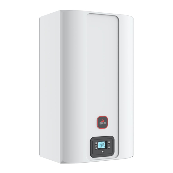
Biasi RINNOVA ADAPTIVE M300V.2025 SM Service Manual
Combi boiler
Hide thumbs
Also See for RINNOVA ADAPTIVE M300V.2025 SM:
- User manual and installation instructions (72 pages) ,
- User manual and installation instructions (80 pages) ,
- User manual and installation instructions (92 pages)
Table of Contents
Advertisement
Quick Links
Wall hung, fanflue, roomsealed, high efficiency gas boiler
Service manual
RINNOVA ADAPTIVE
Models
M300V.2025 SM
M300V.2530 SM
M300V.3035 SM
Leave this manual adjacent to the gas meter
Warning:
Service / repairs must be carried out, only by a qualified Gas Safe Registered
Engineer, who will be responsible for the current Regulations for gas
appliances.
Note:
After servicing, complete the relevant Service Interval Record section of the
Benchmark Checklist of the user and installation manual.
G.C. Appl. No.
47-583-46
COMBI BOILER
47-583-47
COMBI BOILER
47-583-48
COMBI BOILER
Advertisement
Table of Contents

Related Manuals for Biasi RINNOVA ADAPTIVE M300V.2025 SM


Summary of Contents for Biasi RINNOVA ADAPTIVE M300V.2025 SM
- Page 1 Wall hung, fanflue, roomsealed, high efficiency gas boiler Service manual RINNOVA ADAPTIVE Models G.C. Appl. No. M300V.2025 SM 47-583-46 COMBI BOILER M300V.2530 SM 47-583-47 COMBI BOILER M300V.3035 SM 47-583-48 COMBI BOILER Leave this manual adjacent to the gas meter Warning: Service / repairs must be carried out, only by a qualified Gas Safe Registered Engineer, who will be responsible for the current Regulations for gas appliances.
-
Page 3: Table Of Contents
TABLE OF CONTENTS 1 OVERALL INFORMATION . . . . . . . . . . . . . . . . . . . . . . . . . .4 12 PRIMARY CIRCUIT PRESSURE SWITCH . -
Page 4: Overall Information
OVERALL INFORMATION OVERALL INFORMATION 1 .1 Overall View Flue temperature probe NTC and Safety thermal fuse Condensing heat exchanger Burner Expansion Ighition/Detection vessel electrode NTC heating delivery probe - NTC maximum temperature Air/gas mixer C.H. temperature return probe NTC Condensate trap Main circuit C.H. -
Page 5: General Access And Emptying Hydraulic
GENERAL ACCESS AND EMPTYING HYDRAULIC CIRCUITS GENERAL ACCESS AND EMPTYING Pull the lower part of the front panel and lift it upwards (Figure HYDRAULIC CIRCUITS 2.3). 2 .1 Nomenclature Figure 2 .3 To remove the side panels loosen the screws "B" (Figure 2.2) and "C"... -
Page 6: Main Electronic P.c.b. Box
GENERAL ACCESS AND EMPTYING HYDRAULIC CIRCUITS 2 .4 Main electronic p .c .b . box Warning: isolate the boiler from the mains electrici- ty supply before removing any covering or compo- nent . Terminal block lid removal To gain access to the parts located inside the control panel pro- ceed as follows: 1 Remove the front panel of the case. -
Page 7: Emptying The Primary Circuit
GENERAL ACCESS AND EMPTYING HYDRAULIC CIRCUITS 2 .5 Emptying the primary circuit 2 .6 Emptying the D .H .W . circuit 1 Close the C.H. circuit flow and return cocks "M" (Figure 2.10). 1 Close the D.H.W. inlet cock "N" (Figure 2.10). 2 Open one or more hot water taps until the boiler has been completely emptied. -
Page 8: Diagrams
DIAGRAMS DIAGRAMS 3 .1 Wiring diagram M300V SM C.h. temperature Three way probe NTC Electric supply Pump diverter valve flow Flue temp. probe NTC Safety C.h. temperature thermostat Safety probe NTC thermal fuse D.h.w. flow return D.h.w. outlet switch temperature probe NTC Primary circuit pressure switch... -
Page 9: Circuit Voltages
DIAGRAMS 3 .2 Circuit voltages during C.H. or D.H.W. operation Electrical voltages or frequency only during C.H. operation with burner on only during D.H.W. operation 3 way Safety D.H.W. Main circuit Supply network diverter valve Pump thermostat Flow switch pressure switch Gas valve Figure 3 .2 - 9 -... -
Page 10: Fault Finding
FAULT FINDING FAULT FINDING - 10 -... - Page 11 FAULT FINDING - 11 -...
- Page 12 FAULT FINDING - 12 -...
-
Page 13: Display Diagnostic
FAULT FINDING 4 .1 Display diagnostic Primary limitation in D.H.W. mode. The display indications provide help in the diagnosis of fault find- Maintenance required. ing. The wrench symbol is flashing (without show- The control panel display gives other information for the user. ing any error). The following table gives fault code, error and the reson for the fault. - Page 14 FAULT FINDING Figure 4 .5 6 Pressing keys "A" or "C" makes it possible to change the value of parameter 34 from 0 to 48 months. It is possible to set parameter 34 to 99 thereby disabling the maintenance request (symbol will disappear from the display).
-
Page 15: Condensing Heat Exchanger
CONDENSING HEAT EXCHANGER CONDENSING HEAT EXCHANGER 5 .1 Function The Condensing heat exchanger "A" in Figure 5.1 has the func- tion of transferring heat produced from combustion of the gas and from the flue exhausted gas to the water circulating in it. Figure 5 .1 By reducing the combustion products temperature, the latent heat of the vapour is transferred to the water circuit, allowing an extra gain of useful heat. -
Page 16: Cleaning
CONDENSING HEAT EXCHANGER 5 .3 Cleaning If there are deposits of dirt on the coil of the Condensing heat exchanger, clean with a bristle paintbrush and remove the dust with a hoover. Warning: After cleaning or replacement as detailed above, it is deemed necessary to undertake a com- bustion analysis as detailed in chapter "11 .3 Adjust- ment - Chimney Sweep Function"... -
Page 17: H .W . Heat Exchanger
D.H.W. HEAT EXCHANGER D .H .W . HEAT EXCHANGER 6 .1 Function The D.H.W. heat exchanger "A" in Figure 6.1 and Figure 6.3 al- lows the instantaneous transfer of heat from the primary hydrau- lic circuit to the water destined for D.H.W. use. Figure 6 .3 6 Move the exchanger towards the rear of the boiler and extract it to the left. -
Page 18: Pump
PUMP PUMP 7 .2 Removal pump head 7 .1 Function Warning: isolate the boiler from the mains electrici- ty supply before removing any covering or compo- The pump "A" in Figure 7.1 and Figure 7.2 has the function of nent . making the water in the main circuit circulate through the main condensing heat exchanger and therefore through the C.H. -
Page 19: Three Way Diverter Valve
THREE WAY DIVERTER VALVE THREE WAY DIVERTER VALVE 8 .1 Function The diverter valve "A" (Figure 8.1) has the function of modifying the hydraulic circuit of the boiler by means of an electric com- mand given by the electronic control p.c.b. in order to send the water that exits the primary heat exchanger towards the C.H. -
Page 20: Removal Of The Three Way Diverter Valve
THREE WAY DIVERTER VALVE Warning: Please note the electric actuator is ener- 5 Unscrew the connector "H" (Figure 8.6), the C.H. flow con- gized 240VAC even if the boiler is in a standby con- nector and the D.H.W. outlet connector. dition . 6 Remove the D.H.W. heat exchanger (see "6.2 Removal" on page 17). -
Page 21: Main Electronic Control/Ignition P.c.b
MAIN ELECTRONIC CONTROL/IGNITION P.C.B. MAIN ELECTRONIC CONTROL/IGNITION The fundamental function of the Main electronic control/ignition P .C .B . p.c.b. is that of controlling the boiler in relation to the external needs (i.e. heating the dwelling or heating the water for D.H.W. use) and operating in order to keep the temperature of the hy- 9 .1 Function draulic circuits constant. -
Page 22: Checking The Temperature
MAIN ELECTRONIC CONTROL/IGNITION P.C.B. 1 2 3 Figure 9 .2 1 Connector - electric supply p.c.b. 2 Fuse F1 3,15 AF 3 Connector - 3 way diverter valve 4 Connector - pump 5 Connector - controller fan, flue temperature probe NTC, safety thermostat and C.H. -
Page 23: Setting The Boiler Control Function Modes
MAIN ELECTRONIC CONTROL/IGNITION P.C.B. Normally, the result of the comparison between these two signals directly operates the fan speed adjusting the useful output gen- erated in order to stabilize the temperature of the exiting water. If during the D.H.W. mode operation, the temperature of the pri- mary circuit goes over 90°C, the useful output is automatically reduced so that the primary circuit cannot reach excessive tem- peratures. -
Page 24: Checks
MAIN ELECTRONIC CONTROL/IGNITION P.C.B. PARAMETER DIGIT VALUES PARAMETER DIGIT VALUES Boiler model/type External relay operating mode 1 (0=OFF, 1=Zone by remote, 2=Alarm) Type of gas External relay operating mode 2 User interface (0=OFF /TA2=OFF, 1=Zone heat. 2 / Type of domestic hot water exchanger TA2 active, 2= EVG ext / TA2 Active, 3= Anomaly / TA2 Active, 4 =Remote filling Type of primary circuit control device... - Page 25 MAIN ELECTRONIC CONTROL/IGNITION P.C.B. 1 Remove all the body panels (see section "2.2 Case panels" on page 5). 2 Gain access to the parts located inside the Main electronic p.c.b. box as explained in the section "2.4 Main electronic p.c.b. box" on page 6 of this manual. 3 Unscrew the screws "D"...
-
Page 26: Thermal Control In The
MAIN ELECTRONIC CONTROL/IGNITION P.C.B. 9 .7 Thermal control in the mode Switch in the function mode Taking circulator off water from the domestic hot circulator on fan still water circuit? Is primary circuit Main circuit pressure stop circulator (3min) temperature higher than that switch consense? selected? lock memorised? -
Page 27: Mode
MAIN ELECTRONIC CONTROL/IGNITION P.C.B. 9 .8 Thermal control in the mode Switch in the function mode See functioning with the function Taking Request for heat from water from the domestic hot control in the mode room thermostat? water circuit? (sec. 9.7) circulator off fan still circulator on... -
Page 28: Control Panel Electronic P.c.b
CONTROL PANEL ELECTRONIC P.C.B. 10 CONTROL PANEL ELECTRONIC P .C .B . SIGNAL DISPLAYED BY THE LCD FUNCTION 10 .1 Function E01 + Safety lockout due to failed ignition. E02 + Lockout due to safety thermostat. E03 + Generic lockout. Pump circulation failure, insufficient system E04 + pressure or water pressure sensor not con-... - Page 29 CONTROL PANEL ELECTRONIC P.C.B. FUNCTION FUNCTION Anomaly due to probable chimney obstruc- E24 + If the pressure is not correct the value is tion displayed with the flashing symbol. Flame loss for more than 6 consecutive E25 + times. Next maintenance due date (factory setting 12 months).
- Page 30 CONTROL PANEL ELECTRONIC P.C.B. FUNCTION Delay burner ignition due to system setting (flashing uu + flashing temperature). Boiler in chimney sweep function. To activate the chimney sweep function, set "parameter P32=1 ... 4". The following is displayed: LP = minimum D.H.W. hP = minimum output in heating mode cP = maximum output in heating mode dP = maximum D.H.W.
-
Page 31: Gas Valve
GAS VALVE 11 GAS VALVE 11 .3 Adjustment - Chimney Sweep Function Warning: isolate the boiler from the mains electrici- 11 .1 Function ty supply before removing any covering or compo- nent . The gas valve "A" in Figure 11.1 controls the gas inflow to the boiler burner. -
Page 32: Automatic Calibration Of The Gas Valve
GAS VALVE 13 Open at least one hot water tap fully. function” is at maximum output in domestic hot water mode (Figure 11.8). Warning: If the boiler has a correct CO reading in LP but is incorrect CO in dP before adjusting the boiler ensure the supply pressure is within accept- able limits! Figure 11 .4... -
Page 33: Checks
GAS VALVE Pin 1 and 3 = 25 Ohm * 5 To enter in the parameters setting mode press at the same time the 2 keys "H" and "J" (Figure 11.9) and hold in for 5 second until the display shows Figure 11.10. Pin 2 and 4 = 65 Ohm * *at ambient temperature. - Page 34 GAS VALVE 7 Remove the brass plug and turn the plastic screw inside it fully clockwise until it stops. Do not overtight. 8 Turn it counter-clockwise 2 and 3/4 turns. 9 Adjust the gas valve using the flue analyser as described in section "11.3 Adjustment - Chimney Sweep Function"...
-
Page 35: Primary Circuit Pressure Switch
PRIMARY CIRCUIT FLOW SWITCH 12 PRIMARY CIRCUIT PRESSURE SWITCH 12 .2 Removal Warning: isolate the boiler from the mains electrici- 12 .1 Function ty supply before removing any covering or compo- nent . The Primary circuit pressure switch ("A" in Figure 12.1) function is to check the presence of water in the primary hydraulic circuit 1 Remove the front and right hand side panels of the case, turn and that the pressure is above the minimum. -
Page 36: Expansion Vessel And Pressure Gauge
EXPANSION VESSEL AND PRESSURE GAUGE 13 EXPANSION VESSEL AND PRESSURE 13 .3 Removal of the expansion vessel GAUGE Warning: isolate the boiler from the mains electrici- ty supply before removing any covering or compo- 13 .1 Function nent . The Expansion vessel ("A" in Figure 13.1) function is to allow 1 Remove the front and right hand side panels of the case, turn for the volume expansion of the C.H. -
Page 37: H .W . Flow Switch, Filter And Flow Limiter
D.H.W. FLOW SWITCH, FILTER AND FLOW LIMITER 14 D .H .W . FLOW SWITCH, FILTER AND 14 .3 Removal of the sensor FLOW LIMITER Warning: isolate the boiler from the mains electrici- ty supply before removing any covering or compo- 14 .1 Function nent . -
Page 38: Removal Of The Flow Switch Group And D.h.w. Circuit Filter
D.H.W. FLOW SWITCH, FILTER AND FLOW LIMITER 14 .5 Removal of the flow switch group and D.H.W. circuit filter Warning: isolate the boiler from the mains electrici- ty supply before removing any covering or compo- nent . 1 Please remove the sensor first as previously described and ensure it remains dry. 2 Remove the front panel of the case and empty the D.H.W. -
Page 39: Ntc Heating Delivery Probe - Ntc Maximum
TEMPERATURE PROBE 15 NTC HEATING DELIVERY PROBE - 15 .2 Checks NTC MAXIMUM TEMPERATURE, C .H . Temperature-resistance relationship TEMPERATURE RETURN PROBE NTC, D .H .W . TEMPERATURE PROBE NTC Warning: isolate the boiler from the mains electrici- ty supply before removing any covering or compo- 15 .1 Function nent . -
Page 40: Removal Of The D.h.w. Temperature Probe Ntc
TEMPERATURE PROBE Warning: to lubricate the O-ring gaskets exclusively use a silicone base grease compatible to be in con- tact with foods and approved by the local water Au- thorities . Figure 15 .5 Figure 15 .4 15 .5 Removal of the D .H .W . temperature probe Warning: isolate the boiler from the mains electrici- ty supply before removing any covering or compo- nent . -
Page 41: By-Pass Valve
BY-PASS VALVE 16 BY-PASS VALVE reversing the order of removal. 16 .1 Function Warning: to lubricate the O-ring gaskets exclusively The By-pass valve "A" in Figure 16.1 is located between the C.H. use a silicone base grease compatible to be in con- water flow and return and its function is that of guaranteeing a tact with foods and approved by the local water Au- minimum flow across the primary heat exchanger if the circula-... -
Page 42: Fan And Air Box
FAN AND AIR BOX 17 FAN AND AIR BOX 17 .1 Function The function of the Fan "A" (Figure 17.1) is to force the mixture of air and gas into the burner. The function of the Air box "B" is to mix the gas and the air in the right proportion. -
Page 43: Ignition / Detection Electrode And Burner
IGNITION AND DETECTION ELECTRODES 18 IGNITION / DETECTION ELECTRODE 3 Unscrew the screws "B" and remove the electrode "A". AND BURNER 4 Assemble the ignition / detection electrode carrying out the removal operation in reverse order. 18 .1 Function The ignition / detection electrode "A" is fitted on the left side of Warning: A new sealing gasket must be used during the fan-burner group "D". -
Page 44: Removal Of The Rear Insulation
IGNITION AND DETECTION ELECTRODES 18 .6 Checks Check of the spark generator. Warning: isolate the boiler from the mains electrici- ty supply before removing any covering or compo- nent . Burner gasket There is not a significant way to verify the integrity of the spark generator. When the fan turns but the burner does not light a Burner possible cause is a faulty spark generator and it is advisable to replace it to locate the fault. - Page 45 IGNITION AND DETECTION ELECTRODES Excessive exposure to these materials may cause temporary ir- ritation to eyes, skin and respiratory tract. Known hazards - Some people can suffer reddening and itching of the skin. Fibre entry into the eye will cause foreign body irrita- tion, which can cause severe irritation to people wearing contact lenses.
-
Page 46: Flue Temperature Probe Ntc And Safety
FLUE TEMPERATURE PROBE NTC AND SAFETY THERMAL FUSE 19 FLUE TEMPERATURE PROBE NTC AND In case of intervention of this safety device the heat exchanger SAFETY THERMAL FUSE (part shown in Figure 19.3) may be damaged and must be re- placed. - Page 47 FLUE TEMPERATURE PROBE NTC AND SAFETY THERMAL FUSE 12500 12000 11500 11000 10500 10000 9500 9000 8500 8000 7500 7000 6500 6000 5500 5000 4500 4000 3500 3000 2500 2000 1500 1000 °C 20 25 30 35 40 45 50 55 60 65 70 75 80 85 90 95 100 Figure 19 .4 - 47 -...
-
Page 48: Condensate Trap
CONDENSATE TRAP 20 CONDENSATE TRAP 20 .3 Removal Warning: isolate the boiler from the mains electrici- 20 .1 Function ty supply before removing any covering or compo- nent . The condensate trap "A" in Figure 20.1 and Figure 20.2 allows the discharge of the condensate via the condensate drain pipe 1 Remove the front and right case panels. -
Page 49: Short Spare Parts List
SHORT SPARE PARTS LIST 21 SHORT SPARE PARTS LIST G .C . part no . Description Q .ty Manufacturer part no . Burner (mod. M300V.2025 SM) BI1713 100 Burner (mod. M300V.2530 SM - M300V.3035 SM) BI1713 101 Expansion vessel BI1462 100 Condensing heat exchanger (mod. - Page 50 SHORT SPARE PARTS LIST Figure 21 .1 - 50 -...
- Page 52 *1796234660* 17962.3466.0 4221 52A4 Biasi UK Ltd Commercial Road Leamore Enterprise Park WALSALL WS2 7NQ Sales Tel. 01922 714600 Tech. Service Tel. 01922 714636 www.biasi.co.uk...