
Related Manuals for Makita LH1201FL/2


Summary of Contents for Makita LH1201FL/2
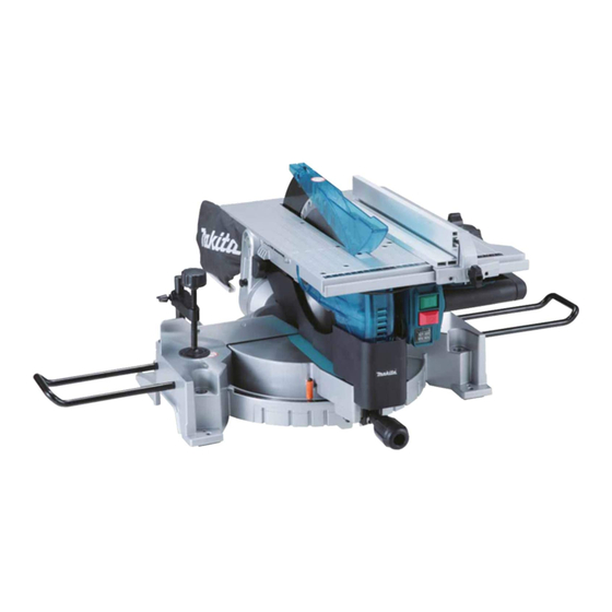
- Page 1 INSTRUCTION MANUAL Table Top Miter Saw LH1201FL 015122 DOUBLE INSULATION IMPORTANT: Read Before Using.
-
Page 2: Specifications
ENGLISH (Original instructions) SPECIFICATIONS Model LH1201FL Blade diameter 305 mm Blade body thickness 1.9 mm or less Hole diameter For all countries other than European countries 25.4 mm For European countries 30 mm Max. Cutting capacities (H x W) with blade 305 mm in diameter in the miter saw mode Miter angle Bevel angle 90°... -
Page 3: General Power Tool Safety Warnings
EC Declaration of Conformity Do not expose power tools to rain or wet conditions. Water entering a power tool will Makita declares that the following Machine(s): increase the risk of electric shock. Designation of Machine: Do not abuse the cord. Never use the cord for Table Top Miter Saw carrying, pulling or unplugging the power tool. - Page 4 14. Remove any adjusting key or wrench before 27. Keep handles dry, clean and free from oil and turning the power tool on. A wrench or a key left grease. ENB088-5 attached to a rotating part of the power tool may result in personal injury.
- Page 5 all moving portions. When lifting or carrying the Your risk from these exposures varies, tool, do not use the guard as a carrying handle. depending on how often you do this type of 19. Clean and be careful not to damage the work.
-
Page 6: Installation
50. Do not perform any operation freehand. FUNCTIONAL DESCRIPTION Freehand means using your hands to support or guide the workpiece, in lieu of a rip fence. 51. Make sure the blade is not contacting the riving CAUTION: knife or workpiece before the switch is turned on. Always be sure that the tool is switched off and unplugged •... -
Page 7: Adjusting The Bevel Angle
Adjusting the bevel angle If any of these blade guards becomes discolored through age or UV light exposure, contact a Makita service center for 1. Lever a new guard. DO NOT DEFEAT OR REMOVE GUARDS. -
Page 8: Laser Radiation
NOTE: unplugged before installing or removing the blade. Use a dry cloth to wipe the dirt off the lens of lamp. Use only the Makita socket wrench provided to • • Be careful not to scratch the lens of lamp, or it may install or remove the blade. -
Page 9: Adjusting Riving Knife
1. Center cover 1. Hex bolt 2. Socket wrench 2. Outer flange 3. Hex bolt 3. Saw blade 4. Lower blade 4. Inner flange guard A 5. Spindle 6. Ring 012190 012194 Press the shaft lock to lock the spindle, use the socket CAUTION: wrench to loosen the hex bolt clockwise. - Page 10 If they are not aligned for any reasons, There are four patterns to position the rip fence as • always have Makita authorized service center repair it. shown in the figure. Rip fence has two slits on its sides, Don't remove the riving knife.
- Page 11 1. Rip fence To change from the pattern A or B to the pattern C 2. Saw blade or D, or in adverse case, remove the square nut, 3. Top blade guard washer and clamping screw (A) from the rip fence holder, then position the clamping screw (A), washer and square nut on the opposite position of the rip fence holder compared to the original...
-
Page 12: Securing Workpiece
CAUTION: Table saw mode When cutting long workpieces, use supports that • 1. Vacuum cleaner are as high as the top surface level of the turn base. 2. Blade cover Do not rely solely on the vertical vise and/or horizontal vise (optional) to secure the workpiece. Thin material tends to sag. -
Page 13: Operation
tightening the screw. If the screw to secure the vise arm CUTTING AS MITER SAW contacts the guide fence, install the screw on the opposite side of vise arm. Make sure that no part of the CAUTION: tool contacts the vise when lowering the handle all the Do not apply excessive pressure on the handle •... -
Page 14: Compound Cutting
and turn table. Switch on the tool without the blade CAUTION: making any contact and wait until the blade attains Never attempt to cut thick or round aluminum • full speed. Then gently lower the handle to the fully extrusions. Thick aluminum extrusions may come lowered position while applying pressure in parallel loose during operation and round aluminum with the blade. -
Page 15: Work Helpers
In case of tools for European countries, flip the Auxiliary fence sub-fence outward before placing the blade cover. 1. Face/edge 140 mm parallel CAUTION: 15 mm 2. Hole(7mm in Always use "work helpers" such as push sticks and • 10 mm diameter) push blocks when there is a danger that your 14 mm... -
Page 16: Carrying Tool
1. Push stick 015131 012218 (2) When the width of rip is narrower than 40 mm, CAUTION: the push stick cannot be used because the Always secure all moving portions before carrying • push stick will strike the top blade guard. Use the tool. -
Page 17: Replacing Carbon Brushes
1. Arm 1. Triangular rule 2. Bevel scale 2. Grip 3. Pointer 3. Guide fence 4. Turn base 012222 015133 45° bevel angle Bevel angle 1. Lever 1. Turn base 2. Arm 2. Lever 3. Pointer 3. 0 ゚ adjusting 4. -
Page 18: Optional Accessories
Only use accessory or attachment for its stated purpose. If you need any assistance for more details regarding these accessories, ask your local Makita Service Center. Steel & Carbide-tipped saw blades • Vise assembly (Horizontal vise) • Vertical vise •... - Page 20 Makita Jan-Baptist Vinkstraat 2, 3070, Belgium Makita Corporation Anjo, Aichi, Japan www.makita.com JM2338A073...