Table of Contents
Advertisement
Quick Links
Advertisement
Table of Contents

Related Manuals for Planar PXN2410


Summary of Contents for Planar PXN2410
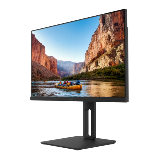
- Page 1 PXN2410 LCD Monitor...
- Page 3 The information contained in this document is subject to change without notice. This document contains proprietary information that is protected by copyright. All rights are reserved. No part of this document may be reproduced, translated to another language or stored in a retrieval system, or transmitted by any means, electronic, mechanical, photocopying, recording, or otherwise, without prior written permission.
-
Page 4: Table Of Contents
TECHNICAL SUPPORT (FAQ) ..................18 ERROR MESSAGE & POSSIBLE SOLUTION ............19 APPENDIX ..........................20 SPECIFICATIONS ......................20 FACTORY PRESET TIMING TABLE ................. 21 CONNECTOR PIN ASSIGNMENT ................22 CONNECTOR PIN ASSIGNMENT ................23 WALL MOUNTING (OPTIONAL) ................24 PLANAR SUPPORT ......................25... -
Page 5: For Your Safety
| FOR YOUR SAFETY Before operating the monitor, please read this manual thoroughly. This manual should be retained for future reference. FCC Class B Radio Frequency Interference Statement WARNING: (FOR FCC CERTIFIED MODELS) NOTE: This equipment has been tested and found to comply with the limits for a Class B digital device, pursuant to Part 15 of the FCC Rules. -
Page 6: Precautions
Disposal of waste equipment by user in private household in the European Union This symbol on the product or on its packaging indicates that this product must not be disposed of with your other household waste. Instead, it is your responsibility to dispose of your waste equipment by handing it over to a designated collection point for the recycling of waste electrical and electronic equipment. - Page 7 • Do not attempt to service the monitor by yourself; opening or removing covers can expose you to dangerous voltages and other hazards. Please refer all servicing to qualified service personnel. • To ensure satisfactory operation, use the monitor only with UL listed computers which have appropriate configured receptacles marked between 100 - 240V AC, Min.
-
Page 8: Special Notes On Lcd Monitors
SPECIAL NOTES ON LCD MONITORS The following symptoms are normal with LCD monitor and do not indicate a problem. NOTES AND CLEANING • Due to the nature of the fluorescent light, the screen may flicker during initial use. Turn off the Power Switch and then turn it on again to make sure the flicker disappears. -
Page 9: Before You Operate The Monitor
| BEFORE YOU OPERATE THE MONITOR FEATURES • 24" Wide Screen IPS Monitor • Recommened Resolution: 1920 x 1080 @ 60Hz • HDMI and Displayport Inputs • Ergonomic Design • Space Saving, Compact Case Design • Integrated 2W speakers Use extreme caution when unpacking your monitor as the deskstand is spring- loaded. -
Page 10: Package List
PACKAGE LIST The product package should include the following items: PXN2410 LCD Monitor Monitor Stand base User's Guide Screws for Base Power cable HDMI cable DP cable... -
Page 11: Installation Instructions
INSTALLATION INSTRUCTIONS Attach the base organizer. -
Page 12: Controls And Connectors
CONTROLS AND CONNECTORS POWER CORD Power Source: 1. Make sure that the power cord is the correct type required in your area. 2. This monitor has an internal universal power supply that allows operation in either 100/120V AC or 220/240V AC voltage area (No user adjustment is required.) 3. -
Page 13: Adjusting The Viewing Angle
ADJUSTING THE VIEWING ANGLE • For optimal viewing it is recommended to look at the full face of the monitor, then adjust the monitor’s angle to your own preference. • Hold the stand so you do not topple the monitor when you change the monitor’s angle. •... -
Page 14: Operating Instructions
| OPERATING INSTRUCTIONS GENERAL INSTRUCTIONS The control buttons are located at the back of the monitor (See Figure 4). Press the power button to turn the monitor on or off. By changing these settings, the picture can be adjusted to your personal preferences. •... -
Page 15: Front Panel Control
FRONT PANEL CONTROL • Power Button: Press this button to switch ON/OFF monitor’s power. • Power Indicator: Blue — Power on mode. Orange —Power saving mode. • [1]: OSD / Exit: Activates OSD menu or exit selection. : Volume / Blue Light Reducer: •... -
Page 16: How To Adjust A Setting
HOW TO ADJUST A SETTING 1. Press the [1] button to activate the OSD window. 2. Press to navigate through the functions. Once the desired function is highlighted, press the [2] button to activate it. If the function selected has a sub-menu, press again to navigate through the sub-menu functions. -
Page 17: Adjusting The Picture
ADJUSTING THE PICTURE Main Menu Main Menu Description Item Icon Menu Item Luminance Contrast Adjusts contrast levels. Brightness Adjusts backlight levels. Eco Mode Picture Adjustment, Standard: Brightness = 90, Contrast = 50. Brightness, Contrast Adjustable Text: Brightness = 20, Contrast = 50. Brightness, Contrast Grayed. - Page 18 Main Menu Main Menu Description Item Icon Menu Item Color Temp. Warm Recall Warm Color Temperature . Normal Recall Normal Color Temperature . Cool Recall Cool Color Temperature . User Adjust R.G.B levels as desired. User-R:Red Gain from Digital-register. User-G:Green Gain from Digital-register. User-B:Blue Gain from Digital-register.
-
Page 19: Plug And Play
PLUG AND PLAY Plug & Play DDC2B Feature This monitor is equipped with VESA DDC2B capabilities according to the VESA DDC STANDARD. It allows the monitor to inform the host system of its identity and, depending on the level of DDC used, communicate additional information about its display capabilities. The DDC2B is a bidirectional data channel based on the I²C protocol. -
Page 20: Technical Support (Faq)
TECHNICAL SUPPORT (FAQ) Problem & Question Possible Solution Power LED is not on * Check if the Power Switch is in the ON position. * Power Cord should be connected. No Plug & Play * Check if the PC system is Plug & Play compatible. * Check if the Video Card is Plug &... -
Page 21: Error Message & Possible Solution
ERROR MESSAGE & POSSIBLE SOLUTION NO SIGNAL: 1. Check that the signal-cable is properly connected, if the connector is loose, tighten the connector's screws. 2. Check the signal-cable's connection pins for damage. INPUT NOT SUPPORT: Your computer has been set to unsuitable display mode, set the computer to display mode given in the following table. -
Page 22: Appendix
| APPENDIX SPECIFICATIONS LCD Panel Driving system TFT Color LCD Size 60.45 cm(23.8"") Pixel pitch 0.2745 (H) x 0.2745 (V) mm Input Video Digital H-Frequency 30 – 85 kHz V-Frequency 48 - 76 Hz Display Colors 16.7 M Max. Resolution 1920 x 1080 @ 75Hz Plug &... -
Page 23: Factory Preset Timing Table
FACTORY PRESET TIMING TABLE Preset HDMI/Displayport/VGA Standard Resolution (Hz) HDMI 640×480@60 640×480@67 640×480@72 640×480@75 720x400@70H SVGA 800x600@56 SVGA 800x600@60 SVGA 800x600@72 SVGA 800x600@75 1024×768@60 1024×768@70 1024×768@72 1024×768@75 SXGA 1280×800@60 SXGA 1280×1024@60 SXGA 1280×1024@70 SXGA 1280×1024@75 WXGA+ 1440×900@60 WXGA+ 1440×900@75 WSXGA+ 1680×1050@60 1280x720@60Hz 1366x768@60Hz... -
Page 24: Connector Pin Assignment
CONNECTOR PIN ASSIGNMENT 20 - Pin Color Display Signal Cable PIN NO. DESCRIPTION PIN NO. DESCRIPTION ML_Lane 3 (n) ML_Lane 0 (p) ML_Lane 3 (p) CONFIG1 ML_Lane 2 (n) CONFIG2 AUX_CH(p) ML_Lane 2 (p) ML_Lane 1 (n) AUX_CH(n) Hot Plug Detect ML_Lane 1 (p) Return DP_PWR ML_Lane 0 (n) -
Page 25: Connector Pin Assignment
CONNECTOR PIN ASSIGNMENT 15 - Pin Color Display Signal Cable PIN NO. DESCRIPTION PIN NO. DESCRIPTION Green Detect Cable Blue Ground Ground DDC-Serial Data Ground H-Sync R-Ground V-Sync G-Ground DDC-Serial Clock B-Ground... -
Page 26: Wall Mounting (Optional)
WALL MOUNTING (OPTIONAL) Refer to the instructions that come with the base mounting kit. To convert your display from a desk-mounted to a wall-mounted display, do the following: 1. Verify that the power button is turned Off, then disconnect the power cord. 2. -
Page 27: Planar Support
| PLANAR SUPPORT Cables and Accessories To find cables and accessories for your Planar monitor, touch screen or other Planar products visit our online store at www.PlanarOnline.com Technical Support Visit Planar at http://www.planar.com/support for operations manuals, touch screen drivers, warranty information and access to Planar's Technical Library for online troubleshooting. - Page 28 Planar Address: 1195 NE Compton Drive, Hillsboro, OR 97006 USA 2021 Q41G24M193507A...