
Related Manuals for AudioCodes M500L


Summary of Contents for AudioCodes M500L
- Page 1 Hardware Installation Manual AudioCodes Mediant™ Series of Media Gateways & Session Border Controllers Mediant 500L Enterprise Session Border Controller (E-SBC) and Media Gateway...
-
Page 3: Table Of Contents
Hardware Installation Manual Contents Table of Contents Introduction ......................9 Unpacking the Device ..................11 Physical Description ..................13 Physical Dimensions and Operating Environment ..........13 Front Panel Description ..................13 3.2.1 LED Descriptions ....................14 3.2.1.1 Power LED ....................14 3.2.1.2 Status LED .................... - Page 4 Mediant 500L List of Figures Figure 3-1: Front Panel .......................... 13 Figure 3-2: Rear Panel .......................... 15 Figure 4-1: Minimum Vertical Space for 19-inch Rack Mounting ............17 Figure 4-2: Positioning Shelf in Rack ..................... 18 Figure 4-3: Positioning the Device's Anti-Slide Rubber Legs into Shelf's Openings ......19 Figure 4-4: Device Mounted on Shelf in 19-inch Rack ................
- Page 5 Customer Support Customer technical support and services are provided by AudioCodes or by an authorized AudioCodes Service Partner. For more information on how to buy technical support for AudioCodes products and for contact information, please visit our Web site at https://www.audiocodes.com/services-support/maintenance-and-support.
- Page 6 Open source software may have been added and/or amended for this product. For further information, please visit our website at http://audiocodes.com/support or contact your AudioCodes sales representative. Warning: The device is an INDOOR unit and therefore, must be installed only indoors. Caution Electrical Shock Do not open or disassemble this device.
- Page 7 Hardware Installation Manual Notices Document Revision Record LTRT Description 10480 Initial document release for Version 7.0. 10481 Connector pinouts updated for serial interface. 10482 Max. power consumption updated. 10483 Status LED for software upgrade. 10484 19-inch rack mount; wall mounting. 10485 AC power cable warning (Japanese).
- Page 8 Mediant 500L Documentation Feedback AudioCodes continually strives to produce high quality documentation. If you have any comments (suggestions or errors) regarding this document, please fill out the Documentation Feedback form site https://online.audiocodes.com/documentation-feedback. Hardware Installation Manual Document #: LTRT-10490...
-
Page 9: Introduction
Notes: • Hardware configurations may change without notice. Currently available hardware configurations are listed in AudioCodes Price Book. For further enquiries, please contact your AudioCodes sales representative. • For information on configuring the device, refer to the device's User’s Manual. - Page 10 Mediant 500L This page is intentionally left blank. Hardware Installation Manual Document #: LTRT-10490...
-
Page 11: Unpacking The Device
• Four anti-slide bumpers for desktop installation • Serial cable adapter • AC/DC power adapter Check, retain and process any documents. If there are any damaged or missing items, notify your AudioCodes sales representative. Media Gateway & E-SBC Mediant 500L... - Page 12 Mediant 500L This page is intentionally left blank. Hardware Installation Manual Document #: LTRT-10490...
-
Page 13: Physical Description
Hardware Installation Manual 3. Physical Description Physical Description This section provides a physical description of the device. Physical Dimensions and Operating Environment The device's physical dimensions and operating environment are listed in the table below: Table 3-1: Physical Dimensions and Operating Environment Specification Value Dimensions (H x W x D) -
Page 14: Led Descriptions
Mediant 500L 3.2.1 LED Descriptions The LED descriptions are provided in the subsequent subsections. 3.2.1.1 Power LED The Power LED indicates whether or not the device is powered on or off, as described in the table below. Table 3-3: Power LED Description Color State Description... -
Page 15: Rear Panel Description
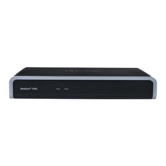
Hardware Installation Manual 3. Physical Description Rear Panel Description The device's rear panel is shown in the figure below and described in the subsequent table. Figure 3-2: Rear Panel Note: The figure above is used only as an example. The hardware configuration depends on the ordered model. -
Page 16: Lan Interface Leds
Mediant 500L 3.3.1 LAN Interface LEDs Each Ethernet port provides a LED for indicating LAN operating status, as described in the table below. Table 3-6: LAN LED Description Color State Description Green Ethernet link established. Flashing Data is being received or transmitted. No Ethernet link. -
Page 17: Mounting The Device
19-inch Rack mounting Wall mounting 19-Inch Rack Mounting You can mount the device in a standard 19-inch rack, using AudioCodes 1U 19-inch rack mount shelf (not supplied). Note: The AudioCodes 1U 19-inch rack mount shelf is not supplied with your product and can be ordered separately from an AudioCodes sales distributor. -
Page 18: Figure 4-2: Positioning Shelf In Rack
Mediant 500L To mount the device in a 19-inch rack: Position the rack mount shelf (not supplied) in the 19-inch rack, aligning the holes of the shelf's side brackets with the holes of the rack's front posts, as shown in the figure below. -
Page 19: Figure 4-3: Positioning The Device's Anti-Slide Rubber Legs Into Shelf's Openings
Hardware Installation Manual 4. Mounting the Device Place the device on the shelf so that the device's front panel faces the front of the rack and the device's four anti-slide rubber legs (located on the bottom of the device) fit into the four square openings on the shelf, as shown in the figure below (viewed from underneath): Figure 4-3: Positioning the Device's Anti-Slide Rubber Legs into Shelf's Openings... -
Page 20: Wall Mounting
Mediant 500L Wall Mounting You can mount the device on a wall using the keyholes on the bottom of the device. To mount the device on a wall: Drill three holes in the wall where you want to mount the device, using the distances between the holes as shown in the figure below: •... - Page 21 Hardware Installation Manual 4. Mounting the Device Media Gateway & E-SBC Mediant 500L...
-
Page 22: Figure 4-6: Protruded Screw Distance From Wall Surface
Mediant 500L Insert wall anchors of the appropriate size into each hole. Thread screws (not supplied) into each of the wall anchors. The recommended screw type is DIN 7982 3.5x25 Phillips flat head. Make sure that the heads extend sufficiently (about 4 mm or 0.157 in.) from the wall for the device's keyholes to hang on: Figure 4-6: Protruded Screw Distance from Wall Surface Hold the device so that it is orientated with the bottom panel with the keyholes facing... -
Page 23: Cabling The Device
Hardware Installation Manual 5. Cabling the Device Cabling the Device This chapter describes the cabling of the device, which includes the following: Connecting LAN interfaces – see Section on page Connecting BRI lines – see Section 5.2.1 on page ... -
Page 24: Figure 5-2: Cabling Lan Ports
Mediant 500L Signal Name Ethernet signal pair (1000Base-T) Shield Chassis ground To connect the device to the LAN: Connect one end of a straight-through RJ-45 Cat 5e or Cat 6 cable to the LAN port, located on the rear panel and labeled GE LAN. Figure 5-2: Cabling LAN Ports Connect the other end of the cable to a network device or entity. -
Page 25: Isdn Bri Interfaces
To protect against electrical shock and fire, use a 26 AWG min wire to connect the BRI ports to the PSTN. Note: BRI interface is a customer-ordered item which is supported only on specific hardware configurations. For more information, contact your AudioCodes sales representative. The BRI cabling specifications include the following: ... -
Page 26: Figure 5-4: Cabling Bri Ports
Mediant 500L To connect a BRI line: Connect the RJ-45 cable to the device's BRI port, located on the rear panel and labeled BRI. Figure 5-4: Cabling BRI Ports Connect the other end of the cable to your ISDN equipment. Hardware Installation Manual Document #: LTRT-10490... -
Page 27: Connecting Pstn Fallback For Bri Lines
The BRI PSTN Fallback feature is a customer-ordered item, which is supported only on specific hardware configurations providing BRI interfaces. For more information, contact your AudioCodes sales representative. • The BRI PSTN Fallback feature has no relation to the PSTN Fallback Software License Key. -
Page 28: Analog Interfaces
Mediant 500L Analog Interfaces This section describes how to connect the device to analog equipment. 5.3.1 Connecting FXS Interfaces The procedure below describes how to cable the device's FXS interfaces. Warnings: • The device is an INDOOR unit and therefore, must be installed only indoors. •... -
Page 29: Connecting Fxo Interfaces
Hardware Installation Manual 5. Cabling the Device To connect the FXS interfaces: Connect one end of an RJ-11 cable to the device's FXS port (labeled FXS), located on the rear panel: Figure 5-7: Connecting FXS Interfaces Connect the other end of the cable to the required telephone interface (e.g., fax machine, dial-up modem, or analog POTS telephone). -
Page 30: Figure 5-8: Rj-11 Connector Pinouts For Fxo Interface
Mediant 500L Notes: • FXO interface is a customer-ordered item. • FXO is the interface replacing the analog telephone and connects to a Public Switched Telephone Network (PSTN) line from the Central Office (CO) or to a Private Branch Exchange (PBX). The FXO is designed to receive line voltage and ringing current, supplied from the CO or the PBX (similar to an analog telephone). -
Page 31: Connecting The Fxs Analog Lifeline
FXO line and calls between these entities can occur. Note: The FXS Analog Lifeline feature is a customer-ordered item and is only supported on specific hardware configurations with combined FXS and FXO interfaces. For more information, contact your AudioCodes sales representative. Cable specifications: Connector Types: RJ-11 ... -
Page 32: Cabling The Serial Interface To A Pc
Mediant 500L Cabling the Serial Interface to a PC The device provides an RS-232 serial interface port on its rear panel. The RS-232 interface port is used to access the device's command line interface (CLI). An RJ-45 to DB-9 female serial cable adapter is supplied for serial cabling: Figure 5-12: RJ-45 to DB-9 Female Cable Adapter Table 5-2: RJ-45 to DB-9 Serial Cable Connector Pinouts... -
Page 33: Connecting A Usb Storage Device
Hardware Installation Manual 5. Cabling the Device Connecting a USB Storage Device The device supports USB storage capabilities, using an external USB hard drive or flash disk (disk on key) connected to the device's USB port. The storage capabilities are configured through CLI and include the following: ... -
Page 34: Connecting To The Power Supply
Mediant 500L Connecting to the Power Supply The device is powered by an external 12V AC/DC power adapter (supplied), connected to a standard alternating current (AC) electrical wall outlet. Table 5-3: Power Specifications Item Description Power Supply Single universal external AC power supply Input Ratings 100-240 VAC, 50-60 Hz Output Ratings... -
Page 35: Figure 5-16: Inserting Plug Into Power Adapter
Hardware Installation Manual 5. Cabling the Device Table 5-4: Power Adapter with Interchangeable Plugs Item Description Plug slot Plug lock Plug release lever DC power cord DC power plug To connect the device to the power supply using the power adapter: Insert the relevant AC plug into the housing power adapter: Insert the top part of the plug into the upper part of the housing slot (1). -
Page 36: Figure 5-17: Cabling To Power Using Power Adapter
Mediant 500L Figure 5-17: Cabling to Power using Power Adapter Plug the power adapter directly into a standard electrical wall outlet. Hardware Installation Manual Document #: LTRT-10490... -
Page 37: Powering On Or Off The Device
Hardware Installation Manual 5. Cabling the Device 5.6.1 Powering On or Off the Device The device is equipped with a power switch, which is located on its rear panel (see Section on page 15) for turning it on or off. ... - Page 38 Website: ©2017 AudioCodes Ltd. All rights reserved. AudioCodes, AC, HD VoIP, HD VoIP Sounds Better, IPmedia, Mediant, MediaPack, What’s Inside Matters, OSN, SmartTAP, User Management Pack, VMAS, VoIPerfect, VoIPerfectHD, Your Gateway To VoIP, 3GX, VocaNom, AudioCodes One Voice and CloudBond are trademarks or registered trademarks of AudioCodes Limited.