Compaq Armada 1700 User Manual
Hp armada 1700: user guide
Hide thumbs
Also See for Armada 1700:
- Reference manual (194 pages) ,
- Specification (11 pages) ,
- White paper (5 pages)
Table of Contents
Advertisement
Quick Links
Advertisement
Table of Contents
Troubleshooting

Related Manuals for Compaq Armada 1700


Summary of Contents for Compaq Armada 1700
-
Page 3: Table Of Contents
preface Symbols ... iv Technician Notes...v Serial Number...v Laser Safety...v CDRH Regulations ...v Battery Notice ... vi Serial Number ... vii Locating Additional Information ... vii chapter 1 1.1 Computer Features and Models ... 1-1 1.2 Computer Options ... 1-3 1.3 External Computer Components... -
Page 4: Table Of Contents
4.3 Preventing Damage to Removable Drives... 4-2 4.4 Preventing Electrostatic Damage... 4-3 chapter 5 5.1 Serial Number ... 5-1 5.2 Disassembly Sequence... 5-2 5.3 Preparing the Computer for Disassembly... 5-3 5.4 Computer Tilt Feet ... 5-7 5.5 Internal Modem... 5-8 5.6 Hard Drive... -
Page 7: Computer
This Maintenance and Service Guide is a troubleshooting guide that can be used for reference when servicing the Compaq Armada 1700 Family of Personal Computers. Using This Guide vii... - Page 8 viii Using This Guide...
- Page 9 WARNING: WARNING: Using This Guide ix...
- Page 10 Compaq Armada 1700 Family of Personal Computers documentation set Microsoft operating system guide Compaq service advisories and bulletins Compaq QuickFind Compaq Service Quick Reference Guide Technical Reference Guide Illustrated Parts Map Compaq Internet site at http://www.Compaq.com x Using This Guide...
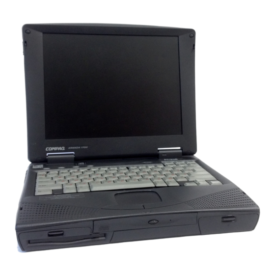
- Page 11 The Armada 1700 Family of Personal Computers is a line of multimedia notebook computers with advanced modularity, processors, and video graphics. This full- function, Mobile Pentium II-based family of notebook computers allows full desktop functionality and connectivity through the use of an optional Convenience Base.
-
Page 12: Hard Drives
Rear-panel ports provide connections for parallel, serial, external monitor, and keyboard/mouse Universal Serial Bus (USB) Compaq Armada 1700 computers are configurable, and may contain any or all of the features listed. All models have 32-MB of standard memory, and may be upgraded to 160-MB. -
Page 13: Diskette Drive
DVD drive for optical Disc Bay 120-MB LS-120 diskette drive for MultiBay 100-MB Zip drive for MultiBay Armada 1700 models support the following convenience base models: Convenience Base II pass through Convenience Base II with Ethernet The computer supports optional 16-, 32-, 64-, and 128-MB memory boards. The memory boards are 66-MHz SDRAM without parity. -
Page 14: External Computer Components
The external battery charger has the following features: Two battery charge slots Accepts Li-ion modular batteries Charges one battery in 1.5 hours Charges two batteries in 3 hours The battery calibration process should be used to discharge the batteries. Supports Compaq or Compaq compatible PS2 keyboards and pointing devices. Supports all VGA Monitors at resolutions up to 1280 u 1024 Supports DDC1 and DDC2b compliant Energy Star monitors The external computer components are illustrated and described in this section. - Page 15 The left side external components are shown in Figure 1-2 and are described in Table 1-1.
- Page 16 The front external components are shown in Figure 1-3 and are described in Table 1-2.
- Page 17 The top external components are shown in Figure 1-4 and are described in Table 1-3.
- Page 18 The right side external components are shown in Figure 1-5 and are described in Table 1-4.
- Page 19 The rear components are shown Figure 1-6 and are described in Table 1-5.
- Page 20 The bottom external components are shown in Figure 1-7 and are described in Table 1-6.
- Page 21 The status panel lights are shown in Figure 1-8 and described in Table 1-7.
-
Page 22: Design Overview
This section presents a design overview of the computer. The overview is limited to field replaceable parts. All replacement parts are listed in Chapter 3. The computer is a traditional clamshell design with a display assembly attached to a system unit. The computer opens to reveal a backlit LCD display and a full-function keyboard. - Page 23 The standard video subsystem consists of: An internal LCD Display 12.1 inch SVGA CTFT display 13.3 inch XGA CTFT display 2 Megabyte frame buffer An inverter to supply AC power to the LCD back-light system A standard external VGA connector for use with CRTs and other VGA compatible displays 40 KByte Video ROM...
-
Page 25: Preliminary Steps
chapter Follow these basic steps when beginning the troubleshooting process: 1. Complete the preliminary steps listed in Section 2.1. 2. Run the Power-On Self-Test (POST) as described in Section 2.3. 3. Run Computer Setup as described in Section 2.5. 4. Run the Computer Checkup (TEST) as described in Section 2.6. 5. - Page 26 Use AC power when running POST, Computer Setup, or Computer Checkup. A low battery condition could initiate Hibernation and interrupt the test. Before running POST and Computer Checkup, complete the following steps: 1. Obtain established passwords. If you must clear the passwords, go to Section 2.2. 2.
-
Page 27: Power-On Self-Test (Post)
The power-on password prevents use of the computer until the password is entered. The setup password prevents unauthorized changes to Computer Setup. To clear the passwords, you must remove all power from the system board. If you do not know the passwords, use the following procedure to clear the password: 1. - Page 28 Warning messages indicate that a potential problem, such as a system configuration error, exists. When is pressed, the system should resume. You should be able to correct problems that produce WARNING messages. When a WARNING message includes the prompt to "RUN SCU," press to run Computer Setup.
- Page 29 If you receive one of the error messages listed below, follow the recommended action.
- Page 30 Fatal errors emit a beep and may display a FATAL message. Fatal errors indicate severe problems, such as a hardware failure. Fatal errors do not allow the system to resume. Some of the Fatal error beep codes are listed at the end of this section.
-
Page 31: Compaq Utilities
Compaq Utilities contain several functions that Determine if various computer devices are recognized by the system and are operating properly. Provide information about the system once it is configured. Compaq Utilities include the following programs: Computer Setup Computer Checkup (TEST) View System Information (INSPECT) To access Compaq Utilities: 1. - Page 32 Categories by type: System Features—security, power, boot management Communication—port, modem, and other communication devices Storage—storage-related devices such as hard drive, CD-ROM drive, diskette drive Input Devices—keyboard, mouse, and other input devices Network—network adapter or other network-related devices Audio—sound properties and audio device settings Video—display timeouts and video device resources Other—miscellaneous devices Categories by connection:...
- Page 33 1. Click 2. Select one of the following Exit options: Save—Saves the new settings and exits Computer Setup. : Some settings may not take effect until the computer is restarted. Ignore—Exits Computer Setup and restores previous settings. Cancel—Returns to Computer Setup. Computer Checkup (TEST) determines whether the various computer components and devices are recognized by the computer and are functioning properly.
- Page 34 Computer Checkup (TEST) error codes occur if the system recognizes a problem while running Computer Checkup. These error codes help identify possible defective assemblies. Tables 2-4 through 2-14 list Computer Checkup error codes, a description of the error condition, and the recommended action for resolving the condition. For removal and replacement procedures, refer to Chapter 5.
- Page 35 Fn + F11 clears the ESCD configuration information. If the Fn + F11 sequence is pressed very early after powering the machine on (after you see the keyboard LEDs blink, but before the video is initialized), CMOS memory will be invalidated. The ESCD is cleared, the machine is reset and boots with the "162 - System Options Not Set"...
- Page 37 Continued...
- Page 38 Continued...
- Page 39 The View System Information (INSPECT) utility provides information about the computer and installed or connected devices. You can display, print, or save the information. In order to access the INSPECT utility, follow the instructions below: 1. Connect a printer if you want to print the INSPECT information. 2.
- Page 40 Compaq Diagnostics provides computer component information when the operating system is working. If you are running Windows 95, access Compaq Diagnostics for Windows by double-clicking My Computer Control Panel Compaq Diagnostics. 1. Run Computer Setup. 2. Click the System Features icon Boot Management box MultiBoot tab.
- Page 42 This section provides information about how to identify and correct some common hardware, memory, and software problems. It also explains several types of messages that may be displayed on the screen. Since symptoms can appear to be similar, carefully match the symptoms of the computer malfunction against the problem description in the Troubleshooting tables to avoid a misdiagnosis.
- Page 43 Continued...
- Page 44 Continued...
- Page 45 The following table lists some common battery problems and recommended actions to take when they occur. The "Solving Power Problems" section in this chapter also may be applicable. Continued...
- Page 46 Continued...
- Page 51 The computer is shipped with the infrared port disabled. The port must be enabled each time the computer is started or restarted. Follow these steps to enable the infrared port. 1. Click Start Settings Control Panel. 2. Double click the Infrared icon. 3.
- Page 52 Continued...
- Page 53 Continued Continued...
- Page 54 Continued “ ” “ ” ‘ ’...
- Page 57 Conduct all tests on a working monitor. If the recommended actions do not solve the problem, replace the display. If the problem persists with a new display, replace the system board. Continued...
- Page 58 Continued...
- Page 60 This chapter provides illustrated parts and references for spare parts for the Compaq Armada 1700 Family of Personal Computers. To review an illustrated parts breakdown of the computer, refer to the Illustrated Parts Map that comes with this guide.
- Page 70 chapter This chapter provides essential information for proper and safe removal and replacement service. You will need the following tools to complete the removal and replacement procedures: Magnetic Torx T-8 screwdriver (for all screws unless otherwise specified) 7-mm hex socket (for bushing guides) Tool kit, Compaq part number 100767-001 (includes connector removal tool, loopback plugs, and case utility tool) Small flat-blade screwdriver (optional)
- Page 71 Cables must be handled with extreme care to avoid damage. Apply only the tension required to unseat or seat the cables during removal and insertion. Handle cables by the connector whenever possible. In all cases, avoid bending, twisting, or tearing cables. Ensure that cables are routed in such a way that they cannot be caught or snagged by parts being removed or replaced.
- Page 72 Many electronic components are sensitive to electrostatic discharge (ESD). Circuitry design and structure determine the degree of sensitivity. Networks built into many integrated circuits provide some protection, but in many cases the discharge contains enough power to alter device parameters or melt silicon junctions. A sudden discharge of static electricity from a finger or other conductor can destroy static-sensitive devices or microcircuitry.
- Page 73 Use the following grounding precautions at workstations: Cover the workstation with approved static-dissipative material (refer to Table 4-2 later in this chapter). Use a wrist strap connected to a properly grounded work surface and use properly grounded tools and equipment. Use field service tools, such as cutters, screwdrivers, and vacuums that are conductive.
- Page 74 Grounding equipment must include either a wrist strap or a foot strap at a grounded workstation. When seated, wear a wrist strap connected to a grounded system. Wrist straps are flexible straps with a minimum of one megohm 10% resistance in the ground cords. To provide proper ground, a strap must be worn snug against the skin.
- Page 75 Table 4-1 shows how humidity affects the electrostatic voltage levels generated by different activities. Table 4-2 lists the shielding protection provided by antistatic bags and floor mats.
-
Page 76: Serial Number
chapter This chapter provides the removal and replacement procedures for the computer subassemblies. The computer serial number should be provided to Compaq support when requesting information or ordering spare parts. The serial number is located on the back of the computer (Figure 5-1). - Page 77 Refer to the disassembly steps before disassembling the computer. Disassemble only the components necessary to gain access to the sub-assembly you are servicing.
- Page 78 Before beginning the removal and replacement procedures, complete the following: 1. Disconnect the modem line cord. 2. Disconnect the AC power and any external devices. 3. Remove the battery pack(s). 4. Remove the MultiBay device. 5. Remove any PC Cards. Before beginning service procedures on the computer, remove all power from the system to prevent damage to the equipment or personal injury.
- Page 79 Remove the battery pack before beginning any internal maintenance on the computer. To remove the battery pack from the computer, complete the following steps: 1 Slide the battery release latch 2 Remove the battery pack.
- Page 80 A diskette drive, an LS-120 diskette drive, a ZIP drive, a second battery pack, or a second hard drive may be installed into the MultiBay. The device in the MultiBay must be removed prior to performing maintenance on the computer. For convenience, a diskette drive is depicted in this sequence. To remove any MultiBay device, complete the following steps: 1.
- Page 81 Remove any installed PC (PCMCIA) Cards before performing any service on the computer. To remove a PC Card, complete the following steps: 1. To release the PC Card eject button, depress the button once 2. To eject the PC Card, firmly depress the PC Card eject button a second time. 3.
- Page 82 There are two tilt feet on the bottom of the computer. To remove a foot, follow the steps listed. 1. Turn the computer bottom side up and position it so that the front of the unit is toward you. 2. Open the foot to the fully extended position. 3.
-
Page 83: Internal Modem
The internal modem is standard on some models and is attainable as an upgrade option on other models. If the model is not equipped with a modem, the modem compartment is sealed by a protective plate underneath the modem cover. For models equipped with a modem, complete the following steps to remove the modem. - Page 84 5. Remove the modem board retaining screw. 6. Carefully pull the modem board release tab and lift the modem from the computer. To replace or install the modem, reverse the procedure. When installing the modem, be sure that the modem release tab is folded on top of the modem before replacing the modem access door.
- Page 85 To remove the Infrared (IR) transceiver module: 1. Prepare the computer for disassembly (Page 5-3). 2. Remove the modem (Page 5-7). 3. Remove the screw from the IR module 4. Disengage the connector from the system board by lifting the corner of the IR module with a screwdriver.
-
Page 86: Hard Drive
The hard drive is held in place with a security screw and a retaining bracket. To remove the hard drive, complete the following steps: 1. Prepare the computer for disassembly (Page 5-3). 2. Turn the computer bottom side up and position it so that the front of the unit is toward you. - Page 87 4. Slide the release latch toward the back of the computer. The cover lid springs open 5. Slide the hard drive cover toward the front of the computer 6. Lift the cover from the computer.
- Page 88 7. Disengage the hard drive from the connector by sliding the hard drive toward the front of the computer. 8. Using the lifting tab, remove the hard drive from the computer. Reverse the above procedure to install the hard drive. Be sure to place the lifting tab inside the computer before replacing the cover.
-
Page 89: Keyboard
To release the keyboard, complete the following procedures. 1. Prepare the computer for disassembly (Page 5-3). 2. Place the computer on the workspace with the front of the unit facing you. 3. Open the display to the vertical position. 4. To release the keyboard, insert the tip of the scribe into each of the keyboard holes, and pull the free end of the scribe towards you. - Page 90 6. Lift the keyboard. 7. Place the keyboard in an upright position. Insert the two tabs on the right side and the tab on the left side of the keyboard into the slots provided on the right of the base enclosure.
- Page 91 1. Release the latch on the keyboard ZIF connector. 2. Slide the strain relief on the flat cable toward the back of the computer, then lift the front edge of the strain relief from the recess. 3. Disconnect the keyboard ribbon cable. 4.
- Page 92 If a memory expansion board option has been previously installed in the computer, it must be removed before another is installed. To remove the memory board, complete the following steps: 1. Prepare the computer for disassembly (Page 5-3). 2. Lift the the keyboard as described (Page 5-14). 3.
- Page 93 5. Rotate the free edge of the memory module upward. 6. At a 45 degree angle, pull the memory module from the slot.
- Page 94 To install a memory board, complete the following steps: 1. Insert the memory board into the memory slot. 2. Pivot the memory board toward the computer compartment. 3. Insert the memory board firmly into place to seat the connections and to engage the locking tabs.
- Page 95 To remove the Lithium Real Time clock (RTC) battery, complete the following steps: 1. Prepare the computer for disassembly (Page 5-3). 2. Raise the keyboard (Page 5-14). 3. Place the tabs on the keyboard in the slots provided in the top cover. 4.
- Page 96 6. Using tweezers, disconnect the RTC battery connector from the system board. 7. Remove the RTC battery. Reverse the procedure to install a replacement RTC battery.
- Page 97 A CD-ROM or DVD-ROM drive can be installed in the optical disc bay. To remove a CD-ROM drive or DVD-ROM drive, complete the following steps: 1. Prepare the computer for disassembly (Page 5-3). 2. Remove the keyboard (Page 5-14). For clarity, the keyboard is shown removed from the computer. The keyboard may be left attached to the system unit for this procedure.
-
Page 98: Display Assembly
To remove the display assembly, complete the following steps: 1. Prepare the computer for disassembly (Page 5-3). 2. Close the cover and place the computer on the workspace top side up and position it so that the connectors on the back panel of the computer are facing you. 3. - Page 99 4. Open the display fully. 5. Lift the hinge covers from the computer. Note that the right and left covers are different. Reverse the procedure to install the hinge covers.
- Page 100 It is not necessary to separate the display and the top cover unless you are replacing the display or the top cover. If you are not replacing the top cover or the display assembly, complete steps 1 through 4 to remove the top cover/display assembly from the base.
- Page 101 5. Close the display. 6. Remove the remaining screw from the left display clutch and the two screws from the right display clutch. 7. Lift the display assembly from the base enclosure. Reverse the procedure to replace the display assembly. Always replace the four loctite screws with the replacement screws supplied in the service kit.
-
Page 102: Top Cover Assembly
To remove the top cover assembly, complete the following procedures: 1. Prepare the computer for disassembly (Page 5-3). 2. Remove the keyboard (Page 5-14). 3. Remove the optical disc bay device (Page 5-22). 4. Remove the RTC battery (Page 5-20). 5. - Page 103 7. Remove the three (3) top cover screws from the back of the system unit.
- Page 104 8. Disconnect the speaker , , touchpad , indicator , and switch cables from the system board. Use the tweezers to release the connectors from the sockets.
- Page 105 9. Lift the top cover from the base enclosure. To replace the top cover assembly, reverse the steps.
- Page 106 To remove the DC-DC converter, complete the following procedures: 1. Prepare the computer for disassembly (Page 5-3). 2. Remove the keyboard (Page 5-14). 3. Remove the RTC battery (Page 5-34). 4. Remove the top cover assembly (Page 5-27). 5. Remove the screws from the converter/audio board shield. 6.
- Page 107 7. Remove the DC-DC converter board from the system board.
- Page 108 To remove the audio board, complete the following procedures: 1. Prepare the computer for disassembly (Page 5-3). 2. Remove the keyboard (Page 5-14). 3. Remove the RTC battery (Page 5-20). 4. Remove the top cover assembly (Page 5-27). 5. Remove the converter/audio board shield (Page 5-31). 6.
- Page 109 To remove the fan, complete the following procedures: 1. Prepare the computer for disassembly (Page 5-3). 2. Remove the keyboard (Page 5-14). 3. Remove the RTC battery (Page 5-20). 4. Remove the top cover assembly (Page 5-27). 5. Remove the converter/audio board shield (Page 5-31). 6.
- Page 110 To remove the system board, complete the following procedures: Prepare the computer for disassembly (Page 5-3). Remove the hard drive (Page 5-11). On modem equipped models, remove the modem (Page 5-7). On IR equipped models, remove the IR module(Page 5-10). Remove the keyboard (Page 5-14).
- Page 111 12. Remove both hex screws from the rear of the base enclosure. 13. Remove the screw from the system board.
- Page 112 14. Lift the right end of the system board from the lower base enclosure. 15. Slide the system board to the right and lift it from the base enclosure. To replace the system board, reverse the steps.
- Page 113 To remove the AC power module, complete the following procedures: 1. Prepare the computer for disassembly as described on page 5-3. 2. Remove the system board (Page 5-35). 3. Remove the ground lead screw. 4. Remove the two screws holding the AC adapter to the system base. 5.
-
Page 114: Ls-120 Drive
chapter This chapter provides physical and performance specifications for the following: Computer Displays Hard drives Diskette drive LS-120 drive ZIP drive CD-ROM drive DVD-ROM drive Battery packs Convenience Base External power sources The chapter also includes: System interrupts System DMA System I/O address System memory map... - Page 125 The automobile/aircraft adapter allows the computer to be used in an automobile or in an aircraft without a drain on the computer's batteries.
- Page 126 The external battery charger charges the Li-Ion battery outside the computer. It may also be used to charge spare batteries.
- Page 128 Continued...
- Page 132 appendix This appendix contains the pin assignments for all external connectors. Connectors...
- Page 133 Connectors...
- Page 134 Connectors...
- Page 135 Continued Connectors...
- Page 136 Continued Continued Connectors...
- Page 137 Continued Connectors...
- Page 138 Connectors...
- Page 139 Connectors...
- Page 140 appendix The wide range input feature of your computer permits it to operate from any line voltage from 100 to 240 volts AC. The power cord set received with the computer meets the requirements for use in the country where you purchased the equipment. Power cord sets for use in other countries must meet the requirements of the country where you use the computer.
- Page 141 1. The flexible cord must be <HAR> Type HO3VV-F, 3-conductor, 0.75 mm conductor size. Power cord set fittings (appliance coupler and wall plug) must bear the certification mark of the agency responsible for evaluation in the country where it will be used. 2.
- Page 142 appendix The convenience bases provide a permanent desktop solution for the computer by eliminating the need to disconnect external devices such as a printer, keyboard, or monitor when you undock the computer. All necessary connections and disconnections are made automatically when the computer is docked and undocked. The following convenience models are available:...
- Page 143 The Convenience Base pass through models and the convenience base with Ethernet models include the following features: (optional)
- Page 144 The convenience base components are illustrated and described in this section. The front and right side convenience base components are shown and identified in this section. Docking latches Docking alignment pins Docking connector Power switch Security cable lock Docking lever Pass-through AC power outlet Battery charge light Suspend button...
- Page 145 The rear components are shown in the following figure and identified in this section: RJ-45 jack (Ethernet model only) Serial connector Parallel connector External monitor connector MIDI/Joystick connector Pointing device connector Keyboard connector Speaker/headphone jack USB connector Audio Line-in jack AC power connector...
-
Page 148: Disassembly Sequence
AC power removal, 5-38 AC power cord 3-conductor, 2-1 spare part number, 3-5 AC Power Module spare part number, 3-8 audio solving problems, 2-19 test error codes, 2-14 audio board removal, 5-33 audio cable removal, 5-33 audio/LED board spare part number, 3-6 automobile/aircraft adapter spare part number, 3-7 specifications, 6-12... -
Page 149: Mass Storage Devices
error codes audio test, 2-14 CD-ROM test, 2-14 computer checkup (TEST), 2-10 diskette drive test, 2-12 keyboard test, 2-11 memory test, 2-11 parallel printer test, 2-11 pointing device interface test, 2-14 processor test, 2-10 serial test, 2-12 video test, 2-13 external computer components bottom, 1-9 front, 1-5... -
Page 150: Documentation
........PC Card removal, 5-6 solving problems, 2-31 PCMCIA removal, 5-6... - Page 151 preliminary steps, 2-2 screen, 2-33, 2-35 without diagnostics, 2-18 video display. See display video test error codes, 2-13 Index-4 warning messages, 2-5 Windows NT infrared connection, 2-27...