Table of Contents
Advertisement
Quick Links
BIPV10-IAT Setup Manual
FCC Information and Copyright
This equipment has been tested and found to comply with the limits of a Class
B digital device, pursuant to Part 15 of the FCC Rules. These limits are designed
to provide reasonable protection against harmful interference in a residential
installation. This equipment generates, uses, and can radiate radio frequency
energy and, if not installed and used in accordance with the instructions, may
cause harmful interference to radio communications. There is no guarantee
that interference will not occur in a particular installation.
The vendor makes no representations or warranties with respect to the
contents here and specially disclaims any implied warranties of merchantability
or fitness for any purpose. Further the vendor reserves the right to revise this
publication and to make changes to the contents here without obligation to
notify any party beforehand.
Duplication of this publication, in part or in whole, is not allowed without first
obtaining the vendor's approval in writing.
The content of this user's manual is subject to be changed without notice and
we will not be responsible for any mistakes found in this user's manual. All the
brand and product names are trademarks of their respective companies.
Advertisement
Table of Contents

Related Manuals for Biostar BIPV10-IAT


Summary of Contents for Biostar BIPV10-IAT
- Page 1 BIPV10-IAT Setup Manual FCC Information and Copyright This equipment has been tested and found to comply with the limits of a Class B digital device, pursuant to Part 15 of the FCC Rules. These limits are designed to provide reasonable protection against harmful interference in a residential installation.
-
Page 2: Table Of Contents
Table of Contents Chapter 1: Introduction ........3 Before You Start ................3 Package Checklist ................3 Mainboard Specification..............4 Rear Panel..................5 Mainboard Layout ................6 Chapter 2: Installation .......... 7 CPU...................... 7 Fan Header..................7 System Memory.................. 8 Power Supply .................. -
Page 3: Chapter 1: Introduction
BIPV10-IAT CHAPTER 1: INTRODUCTION EFORE TART Thank you for choosing our product. Before you start installing the mainboard, please make sure you follow the instructions below: Prepare a dry and stable working environment with sufficient lighting. Always disconnect the system from power outlet before operation. -
Page 4: Mainboard Specification
Mini-ITX Mainboard Manual AINBOARD PECIFICATION Specification Optional for: Intel Atom CPU On-board N455 @1.66GHz (TDP 6.5W) D425 @1.8GHz (TDP 10W) N550 dual core @1.5GHz (TDP 8.5W) Pineview-D Processor D525 dual core @ 1.8GHz (TDP 13W) Supports up 800 MHz Chipset Intel NM10 Express Chipset Max Shared Video Memory is 384 MB -- integrated VGA support up to SXGA+... -
Page 5: Rear Panel
USB Port Audio Jack (Line-out/Mic) Optional for x3 (Line-in/Line-out/Mic) Board Size 170 mm (W) x 170 mm (L) Mini-ITX Biostar reserves the right to add or remove Windows XP/XPE, Linux Support support for any OS with or without notice. ANEL... -
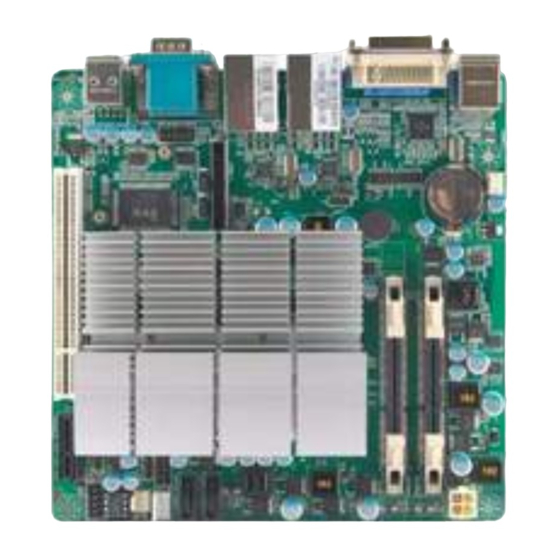
Page 6: Mainboard Layout
Mini-ITX Mainboard Manual AINBOARD AYOUT J CFAN 1 JP WR1 JKB MS1 BAT1 DIMM A2 VG A_DV I1 DIMM A1 JAT1 Intel JRJ4 5USB 1 Atom JRJ4 5USB 2 CU 1 SATA2 JPRNT1 SATA1 JP C1 NM10 JD IO1 JPC2 JUSB 1 F_AUDIO1 PE 1... -
Page 7: Chapter 2: Installation
BIPV10-IAT CHAPTER 2: INSTALLATION The mainboard includes an embedded Intel Atom N455/N550/D525/D425 processor, and a heatsink has been installed to provide sufficient cooling. EADER The fan header supports cooling-fans built in the system. The fan cable and connector may be different due to the fan manufacturer. -
Page 8: System Memory
Mini-ITX Mainboard Manual YSTEM EMORY DIMMA1/DIMMA2: Memory Module (204pin SO-DIMM) DIMMA 2 DIMMA 1 Align a DIMM on the slot such that the notch on the DIMM matches the break on the Slot. Insert the DIMM firmly into the slot until the retaining chip snap back in place and the DIMM is properly seated. -
Page 9: Power Supply
BIPV10-IAT OWER UPPLY JPWR1: ATX Power Source Connector (4-pin) This connector provides +12V to system power circuit. Assignment +12V +12V Ground Ground JHDD1: SATA Power Connector This connector provides power connection of SATA devices. Assignment +12V +3.3V... -
Page 10: Onboard Slot/Connector/Header/Jumper
Mini-ITX Mainboard Manual NBOARD ONNECTOR EADER UMPER PCI1: Peripheral Component Interconnect Slot This mainboard is equipped with 1 standard PCI slot. PCI stands for Peripheral Component Interconnect, and it is a bus standard for expansion cards. This PCI slot is designated as 32 bits. PCI1 PE1: Mini PCI-E Slot This mainboard is equipped with 1 Mini PCI-E Slot. - Page 11 BIPV10-IAT PEX1: PCI-Express x1 Slot PCI-Express 1.1 compliant. Data transfer bandwidth up to 250MB/s per direction; 500MB/s in total. PCI-Express supports a raw bit-rate of 2.5Gb/s on the data pins. SATA1/SATA2: Serial ATA Connectors These next generation connectors support the thin Serial ATA cable for primary internal storage devices.
- Page 12 Mini-ITX Mainboard Manual JUSB1: USB 2.0 Connector The mainboard provides 1 front USB pin connector, allowing up to 2 additional USB 2.0 ports up to maximum throughput of 480 Mbps. Connect the USB cable into the pin header for using high-speed USB interface peripherals. Assignment Assignment +5V (fused)
- Page 13 BIPV10-IAT JDIO1: Digital I/O Connector This connector offers 4-pair of digital I/O functions and address is set in BIOS. The default address is: DI01 -> 48CH BIT6-> GPIO6 DI02 -> 48CH BIT7-> GPIO7 DI03 -> 48DH BIT0-> GPIO8 DI04 -> 48DH BIT1-> GPIO9 DO01 ->...
- Page 14 Mini-ITX Mainboard Manual JCMOS1: Clear CMOS Header * Placing the jumper on pin2-3 allows user to restore the BIOS safe setting and the CMOS data. Please carefully follow the procedures to avoid damaging the mainboard. Pin 1-2 Close: (Default) Normal Operation. Pin 2-3 Close: Clear CMOS data.
- Page 15 BIPV10-IAT F_AUDIO1: Front Panel Audio Header This is an interface for the front panel audio cable that allows convenient connection and control of audio devices. This header allows only HD audio front panel connector; AC’97 connector is not acceptable. Assignment...
- Page 16 Mini-ITX Mainboard Manual JPC1: Voltage Switch Header for JCOM1A This header is for controlling the Pin9 of JCOM1A to switch Ring or 5V. Pin 1-2 Close: Pin9=5V Pin 2-3 Close: Pin9=Ring (Default) JPC2: Voltage Switch Header for JCOM1B This header is for controlling the Pin9 of JCOM1B to switch Ring or 5V. Pin 1-2 Close: Pin9=5V Pin 2-3 Close:...
- Page 17 BIPV10-IAT JPRNT1: Printer Port Connector This header allows you to connect printer port on the PC. Assignment Assignment -Strobe Ground -ALF Data 6 Data 0 Ground -Error Data 7 Data 1 Ground -Init -ACK Data 2 Ground -Scltin Busy Data 3...
-
Page 18: Chapter 3: Bios Setup
Mini-ITX Mainboard Manual CHAPTER 3: BIOS SETUP Introduction The purpose of this chapter is to describe the settings in the AMI BIOS Setup program on this motherboard. The Setup program allows users to modify the basic system configuration and save these settings to CMOS RAM. The power of CMOS RAM is supplied by a battery so that it retains the Setup information when the power is turned off. - Page 19 BIPV10-IAT PCI Bus Support This AMI BIOS also supports Version 2.3 of the Intel PCI (Peripheral Component Interconnect) local bus specification. DRAM Support DDR2 SDRAM (Double Data Rate II Synchronous DRAM) is supported. Supported CPUs This AMI BIOS supports the Intel CPU.
-
Page 20: Main Menu
Mini-ITX Mainboard Manual Once you enter AMI BIOS Setup Utility, the Main Menu will appear on the screen providing an overview of the basic system information. BIOS SETUP UTILITY Main Advanced PCIPnP Boot Chipset Exit System Overview Use [ENTER], [TAB] or [SHIFT-TAB] to AMI BIOS select a field. - Page 21 BIPV10-IAT IDE Configuration The BIOS will automatically detect the presence of IDE/SATA devices. There is a sub-menu for each IDE/SATA device. Select a device and press <Enter> to enter the sub-menu of detailed options. BIOS SETUP UTILITY Main IDE Confuguration...
- Page 22 Mini-ITX Mainboard Manual The BIOS detects the information and values of respective devices, and these information and values are shown below to the name of the sub-menu. Type Select the type of the SATA drive. Options: Auto (Default) / CD/DVD / ARMD / Not Installed LBA/Large Mode Enable or disable the LBA mode.
-
Page 23: Advanced Menu
BIPV10-IAT DVANCED The Advanced Menu allows you to configure the settings of CPU, Super I/O, Power Management, and other system devices. Notice Beware of that setting inappropriate values in items of this menu may cause system to malfunction. BIOS SETUP UTILITY... - Page 24 Mini-ITX Mainboard Manual Max CPUID Value Limit When the computer is booted up, the operating system executes the CPUID instruction to identify the processor and its capabilities. Before it can do so, it must first query the processor to find out the highest input value CPUID recognizes. This determines the kind of basic information CPUID can provide the operating system.
- Page 25 BIPV10-IAT SuperIO Configuration BIOS SETUP UTILITY Advanced Configure ITE8718 Super IO Chipset Allows BIOS to Select Serial Port1 Base Serial Port1 Address [3F8/IRQ4] Addresses. Serial Port2 Address [2F8/IRQ3] Parallel Port Address [378] Parallel Port Mode [Normal] Parallel Port IRQ [IRQ7]...
- Page 26 Mini-ITX Mainboard Manual Watch Dog Degree This item allows you to determine the functional degree of Watch Dog. Options: Second (Default) / Minute Watch Dog Timer Options: 0 for disabled (Default) / Min=1, Max=65536 Hardware Health Configuration This item shows the system temperature, fan speed, and voltage information. BIOS SETUP UTILITY Advanced Hardware Health Configuration...
- Page 27 BIPV10-IAT Smart Fan Configuration BIOS SETUP UTILITY Advanced Smart Fan Configuration When you choice [Auto] ,[3Pin] or [4Pin], JSFAN1 Smart Fan [Auto] please run the Smart Fan Calibration calibration to define Control Mode the Fan parameters for Smart Fan control...
- Page 28 Mini-ITX Mainboard Manual Fan Ctrl Start Value When CPU temperature arrives to the set value, the CPU/System fan will work under Smart Fan Function mode. Options: 0~127 (With the interval of 1) Fan Ctrl Sensitive Increasing the value of slope PWM will raise the speed of CPU fan. Options: 0~127 (With the interval of 1) ACPI Configuration BIOS SETUP UTILITY...
- Page 29 BIPV10-IAT Advanced ACPI Configuration BIOS SETUP UTILITY Advanced Advanced ACPI Configuration Enable RSDP pointers to 64-bit Fixed System ACPI Version Features [ACPI v1.0] Description Tables. ACPI APIC support [Enabled] ACPI version has some AMI OEMB table [Enabled] Headless mode [Disabled]...
- Page 30 Mini-ITX Mainboard Manual Chipset ACPI Configuration BIOS SETUP UTILITY Advanced South Bridge ACPI Configuration Energy Lake Feature [Disabled] APIC ACPI SCI IRQ [Disabled] High Performance Event Timer [Disabled] HPET Memory Address [FED00000h] Select Screen Select Item Change Option General Help Save and Exit Exit vxx.xx (C)Copyright 1985-200x, American Megatrends, Inc.
- Page 31 BIPV10-IAT RTC Alarm Time You can choose the system boot up time, input hour, minute and second to specify. Resume On PME# This item allows you to disable or enable PME to generate a wake event. Options: Disabled (Default) / Enabled...
- Page 32 Mini-ITX Mainboard Manual USB 2.0 Controller Mode This item allows you to select the operation mode of the USB 2.0 controller. Options: HiSpeed (Default) USB 2.0-480Mbps FullSpeed USB 1.1-12Mbps BIOS EHCI Hand-Off This item allows you to enable support for operating systems without an EHCI hand-off feature.
-
Page 33: Pci/Pnp Menu
BIPV10-IAT PCI/P This section describes configuring the PCI bus system. PCI, or Personal Computer Interconnect, is a system which allows I/O devices to operate at speeds nearing the speed of the CPU itself uses when communicating with its own special components. - Page 34 Mini-ITX Mainboard Manual Allocate IRQ to PCI VGA This item allows BIOS to choose a IRQ to assign for the PCI VGA card. Options: Yes (Default) / No Palette Snooping Some old graphic controllers need to “snoop” on the VGA palette and then map it to their display as a way to provide boot information and VGA compatibility.
- Page 35 BIPV10-IAT PCI Resource BIOS SETUP UTILITY PCIPnP PCI Resource Available: Specified IRQ is available to be IRQ3 [Available] used by PCI/PnP IRQ4 [Available] devices. IRQ5 [Available] Reserved: Specified IRQ7 [Available] IRQ is reserved for IRQ9 [Available] use by Legacy ISA...
-
Page 36: Boot Menu
Mini-ITX Mainboard Manual This menu allows you to setup the system boot options. BIOS SETUP UTILITY Main Advanced PCIPnP Boot Chipset Exit Boot Settings Configuration Specifies the Boot Device Priority sequence. > Boot Device Priority > Hard Disk Drives > Removable Drives >... - Page 37 BIPV10-IAT Quick Boot Enabling this option will cause an abridged version of the Power On Self-Test (POST) to execute after you power up the computer. Options: Enabled (Default) / Disabled Full Screen LOGO Disaply This item allows you to enable/disable Full Screen LOGO Show function.
- Page 38 Mini-ITX Mainboard Manual BOOT SUCCESS BEEP When this item is set to Enabled, BIOS will let user know boot success with beep. Options: Enabled (Default) / Disabled...
-
Page 39: Chipset Menu
BIPV10-IAT HIPSET This submenu allows you to configure the specific features of the chipset installed on your system. This chipset manage bus speeds and access to system memory resources, such as DRAM. It also coordinates communications with the PCI bus. - Page 40 Mini-ITX Mainboard Manual DRAM Frequency This item allows you to set the frequency of DRAM. Options: Auto (Default) / Max MHz Configure DRAM timing by SPD This item allows you .to determine DRAM timing by SPD Options: Enabled (Default) / Disabled DRAM CAS# Latency Options: 5 (Default) / 3 / 4 / 6 DRAM RAS# to CAS# Delay...
- Page 41 BIPV10-IAT Video Function Configuration BIOS SETUP UTILITY Chipset Video Function Configuration Options DVMT Mode Select [DVMT Mode] Fixed Mode DVMT/FIXED Memory [256MB] DVMT Mode Boot Display Device [CRT + DVI] LVDS SUPPORT [Enabled] Select Screen Select Item Change Option General Help...
- Page 42 Mini-ITX Mainboard Manual South Bridge Configuration BIOS SETUP UTILITY Chipset South Bridge Chipset Configuration Options USB Functions [8 USB Ports] Disabled USB 2.0 Controller [Enabled] 2 USB Ports HDA Controller [Auto] 4 USB Ports SMBUS Controller [Enabled] 6 USB Ports 8 USB Ports Onboard LAN 1 [Enabled]...
- Page 43 BIPV10-IAT SMBUS Controller This BIOS feature controls the I/O buffers for the SMBus. Options: Enabled (Default) / Disabled Onboard LAN 1/2 This item allows you to enable or disable the Onboard LAN. Options: Enabled (Default) / Disabled Onboard LAN ROM 1/2 This item allows you to select the Onboard LAN Boot ROM.
- Page 44 Mini-ITX Mainboard Manual Relaxed Ordering The item enables/disables PCI Express Device Relaxed Ordering. Options: Auto (Default) / Disabled / Enabled Maximum Payload Size The item sets Maximum Payload of PCI Express Device or allows System BIOS to select the value. Options: Auto (Default) / 128 Byte / 256 Byte / 512 Byte / 1024 Byte / 2048 Byte / 4096 Byte Extended Tag Field...
-
Page 45: Exit Menu
BIPV10-IAT This menu allows you to load the optimal default settings, and save or discard the changes to the BIOS items. BIOS SETUP UTILITY Main Advanced PCIPnP Boot Chipset Exit Exit Options Exit system setup after saving the Save Changes and Exit changes. - Page 46 Mini-ITX Mainboard Manual Security This sub-menu allows you to provide/revise supervisor and user password. BIOS SETUP UTILITY Exit Security Settings Install or Change the password. Supervisor Password :Not Installed User Password :Not Installed Change Supervisor Password User Access Level [Full Access] Change User Password Clear User Password Password Check...
- Page 47 BIPV10-IAT Password Check This item is for setting the timing that checking password. Options: Setup (Default) / Always Boot Sector Virus Protection This option allows you to choose the VIRUS Warning feature that is used to protect the IDE Hard Disk boot sector. If this function is enabled and an attempt is made to write to the boot sector, BIOS will display a warning message on the screen and sound an alarm beep.
-
Page 48: Chapter 4: Useful Help
Mini-ITX Mainboard Manual CHAPTER 4: USEFUL HELP RIVER NSTALLATION After you installed your operating system, please insert the Fully Setup Driver CD into your optical drive and install the driver for better system performance. You will see the following window after you insert the CD The setup guide will auto detect your mainboard and operating system. -
Page 49: Ami Bios Beep Code
BIPV10-IAT AMI BIOS B Boot Block Beep Codes Number of Beeps Description No media present. (Insert diskette in floppy drive A:) “AMIBOOT.ROM” file not found in root directory of diskette in Insert next diskette if multiple diskettes are used for recovery... -
Page 50: Troubleshooting
Mini-ITX Mainboard Manual ROUBLESHOOTING Probable Solution There is no power in the system. Make sure power cable is Power LED does not shine; the securely plugged in. fan of the power supply does not Replace cable. work Contact technical support. Indicator light on keyboard does not shine.