Table of Contents
Advertisement
M The author assumes no responsibility for
any errors or omissions that may appear
in this document nor does the author make
a commit ment to up date the information
contained herein.
M Third-party brands and names are the
property of their respective owners.
M Please do not remove any labels on
motherboard, this may void the warranty of
this motherboard.
M Due to rapid change in technology, some
of the specifications might be out of date
before publication of this booklet.
Advertisement
Table of Contents

Related Manuals for Gigabyte GA-7VKMP


Summary of Contents for Gigabyte GA-7VKMP
- Page 1 M The author assumes no responsibility for any errors or omissions that may appear in this document nor does the author make a commit ment to up date the information contained herein. M Third-party brands and names are the property of their respective owners. M Please do not remove any labels on motherboard, this may void the warranty of this motherboard.
-
Page 3: Declaration Of Conformity
(Stamp) Declaration of Conformity We, Manufacturer/Importer (full address) G.B.T. Technology Träding GMbH declare that the product Mother Board GA-7VKMP is in conformity with in accordance with 89/336 EEC-EMC Directive EN 61000-3-2* EN 60555-2 EN 61000-3-3* EN 60555-3 EN 50081-1... - Page 4 (2) this device must accept any inference received, including that may cause undesired operation. Representative Person’s Name: G.B.T. INC. (U.S.A.) Address: 17358 Railroad Street City of Industry, CA 91748 (818) 854-9338/ (818) 854-9339 Motherboard GA-7VKMP ERIC LU Signature: Eric Lu Date: July 23, 2002...
- Page 5 GA-7VKMP Series AMD Athlon /Athlon XP/Duron Socket A ™ ™ ™ Processor Motherboard USER'S MANUAL AMD Athlon /Athlon XP/Duron Socket A Processor Motherboard ™ ™ ™ Rev. 3401 12ME-7VKMP-3401...
-
Page 6: Table Of Contents
WARNING !... 4 Chapter 1 Introduction ... 5 Features Summary ... 5 GA-7VKMP / GA-7VKMP-P Motherboard Layout ... 7 GA-7VKMP-SI Motherboard Layout ... 8 Chapter 2 Hardware Installation Process ... 9 Step 1: Install the Central Processing Unit (CPU) ...10 Step 1-1: CPU Speed Setup ... - Page 7 Q-Flash Utility Introduction ... 56 @BIOS Introduction...58 ™ EasyTune 4 Introduction ...59 ™ 2- / 4- / 6-Channel Audio Function Introuction Chapter 5 Appendix ...67 For GA-7VKMP only. For GA-7VKMP-P only. ) ... For GA-7VKMP-SI only. - 3 - Table of Content...
-
Page 8: Item Checklist
Quick PC Installation Guide RAID Manual WARNING! Computer motherboards and expansion cards contain very delicate Integrated Circuit (IC) chips. To protect them against damage from static electricity, you should follow some precautions whenever you work on your computer. Unplug your computer when working on the inside. -
Page 9: Chapter 1 Introduction
Chipset Memory I/O Control Slots On-Board IDE On-Board Peripherals 24.3cm x 21.0cm Micro ATX size form factor, 4 layers PCB GA-7VKMP Series Motherboard: GA-7VKMP, GA-7VKMP-P or GA-7VKMP-SI Socket A processor AMD Athlon /Athlon XP/Duron (K7) Socket A processor ™ ™... - Page 10 CPU, chipset and most of the peripherals. Whether your system can run under these specific bus frequencies properly will depend on your hardware configurations, including CPU, Chipsets, SDRAM, Cards…etc. For GA-7VKMP only. For GA-7VKMP-P only. GA-7VKMP Series Motherboard Realtek ALC101 CODEC...
-
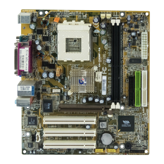
Page 11: Ga-7Vkmp / Ga-7Vkmp-P Motherboard Layout
GA-7VKMP / GA-7VKMP-P Motherboard Layout KB_MS COMB F_AUDIO SUR_CEN AUX_IN CODEC CD_IN 8100BL SPDIF For GA-7VKMP only. For GA-7VKMP-P only. SOCKET A VIA KM266 PCI1 BIOS PCI2 BATTERY PCI3 F_USB1 F_USB2 SPDIF_IN For GA-7VKMP-SI only. - 7 - RAM_LED CLK_JP... -
Page 12: Ga-7Vkmp-Si Motherboard Layout
GA-7VKMP-SI Motherboard Layout KB_MS COMB F_AUDIO SUR_CEN AUX_IN CODEC CD_IN 8100BL SPDIF GA-7VKMP Series Motherboard SOCKET A VIA KM266 PCI1 BIOS PCI2 BATTERY PCI3 F_USB1 F_USB2 - 8 - RAM_LED CLK_JP VIA VT8235 S_IRQ BUZZER F_PANEL PWR_LED... -
Page 13: Chapter 2 Hardware Installation Process
Chapter 2 Hardware Installation Process To set up your computer, you must complete the following steps: Step 1 -Set system Jumper (CLK_JP) Step 2 -Install the Central Processing Unit (CPU) Step 3 -Install memory modules Step 4 -Install expansion cards Step 5 -Connect ribbon cables, cabinet wires and power supply Step 6 -Setup BIOS software Step 7 -Install supporting software tools... -
Page 14: Step 1: Install The Central Processing Unit (Cpu)
Step 1: Install the Central Processing Unit (CPU) Step 1-1: CPU Speed Setup The system bus frequency can be switched at 100/133MHz and auto by adjusting CLK_JP. (The frequency ratio depend on CPU.) GA-7VKMP Series Motherboard 1-2 close: 100MHz 2-3 close: 133MHz CLK_JP... -
Page 15: Step 1-2: Cpu Installation
Step 1-2: CPU Installation CPU Top View Socket Actuation Lever 1. Pull up the CPU socket lever and up to 90-degree angle. Please make sure the CPU type is supported by the motherboard. If you do not match the CPU socket Pin 1 and CPU cut edge well, it will cause improper installation. -
Page 16: Step 1-3: Cpu Heat Sink Installation
Please refer to CPU heat sink user's manual for more detail installation procedure. GA-7VKMP Series Motherboard 2. Use qualified fan approved by AMD. 4. Make sure the CPU fan is plugged to the CPU fan connector, than in- stall complete. -
Page 17: Step 2: Install Memory Modules
Step 2: Install memory modules The motherboard has 2 dual inline memory module (DIMM) sockets. The BIOS will automatically detects memory type and size. To install the memory module, just push it vertically into the DIMM socket. The DIMM module can only fit in one direction due to the notch. Memory size can vary between sockets. -
Page 18: Step 3: Install Expansion Cards
7. Power on the computer, if necessary, setup BIOS utility of expansion card from BIOS. 8. Install related driver from the operating system. AGP Card GA-7VKMP Series Motherboard Please carefully pull out the small white- drawable bar at the end of the AGP slot when you try to install/ uninstall the AGP card. -
Page 19: Step 4: Connect Ribbon Cables, Cabinet Wires And Power Supply
Step 4: Connect ribbon cables, cabinet wires and power supply Step 4-1 : I/O Back Panel Introduction PS/2 Keyboard and PS/2 Mouse Connector PS/2 Mouse Connector (6 pin Female) PS/2 Keyboard Connector (6 pin Female) USB & LAN Connector USB 0 USB 1 This connector supports standard PS/2 key- board and PS/2 mouse. -
Page 20: Audio Connectors
60. For GA-7VKMP only. For GA-7VKMP-P only. GA-7VKMP Series Motherboard ** Only for GA-7VKMP-SI. This motherboard sutports 1 standard COM port,1 VGA port and 1 LPT port. Device like printer can be connected to LPT port; mouse and modem etc. -
Page 21: Step 4-2 : Connectors Introduction
3) ATX 4) FDD 5) IDE1 / IDE2 6) RAM_LED 7) F_PANEL 8) PWR_LED 9) F_AUDIO 10) AUX_IN For GA-7VKMP only. For GA-7VKMP-P only. 11) CD_IN 12) SUR_CEN 13) SPDIF 14) SPDIF_IN 15) IR 16) COMB 17) F_USB1 / F_USB2... - Page 22 5V SB (Stand by +5V) Power Good 3.3V 3.3V GA-7VKMP Series Motherboard Please note, a proper installation of the CPU cooler is essential to prevent the CPU from running under abnormal condition or damaged by overheating. The CPU fan connector supports Max.
- Page 23 4) FDD (Floppy Connector) 5) IDE1 / IDE2 (IDE1 / IDE2 Connector) 6) RAM_LED Please connect the floppy drive ribbon cables to FDD. It supports 360K, 1.2M, 720K, 1.44M and 2.88M bytes floppy disk types. The red stripe of the ribbon cable must be the same side with the Pin1.
- Page 24 F_PANEL connector according to the pin assignment above. 8) PWR_LED MPD+ MPD- MPD- GA-7VKMP Series Motherboard Open: Normal Operation Close: Entering Green Mode Pin 1: LED anode(+) Pin 2: LED cathode(-) Pin 1: LED anode(+)
- Page 25 12) SUR_CEN (Surround Center Connector) CENTER_OUT BASS_OUT SUR OUT(R) SUR OUT(L) For GA-7VKMP only. For GA-7VKMP-P only. If you want to use Front Audio connector, you must remove 5-6, 9-10 Jumper. In order to utilize the front audio header, your chassis must Front Audio (L) have front audio connector.
- Page 26 DSR2 RTS2 CTS2 9 10 For GA-7VKMP only. For GA-7VKMP-P only. GA-7VKMP Series Motherboard The SPDIF output is capable of providing d i g i t a l a u d i o t o e x t e r n a l s p e a k e r s o r compressed AC3 data to an external Dolby Digital Decoder.
- Page 27 Signal 19) BATTER Y (Battery) 20) CI (CASE OPEN) Signal For GA-7VKMP only. For GA-7VKMP-P only. Be careful with the polarity of the front panel USB connector. Check the pin assignment while you connect the front panel USB cable. Please...
- Page 28 GA-7VKMP Series Motherboard - 24 -...
-
Page 29: Chapter 3 Bios Setup
Chapter 3 BIOS Setup BIOS Setup is an overview of the BIOS Setup Program. The program that allows users to modify the basic system configuration. This type of information is stored in battery-backed CMOS RAM so that it retains the Setup information when the power is turned off. ENTERING SETUP Powering ON the comput e r and pressing <Del>... -
Page 30: The Main Menu (For Example: Bios Ver. : F1H)
This setup page includes all the adjustable items of AMI special enhanced features. Chipset Features Setup This setup page includes all the adjustable items of chipset special features. GA-7VKMP Series Motherboard INTEGRATED PERIPHERALS HARDWARE MONITOR & MISC SETUP SUPERVISOR PASSWORD... -
Page 31: Power Management Setup
Power Management Setup This setup page includes all the adjustable items of Green function features. PNP/PCI Configuration This setup page includes all the adjustable configurations of PCI & PnP ISA resources. Load Fail-Safe Defaults Load Fail-Safe Defaults option loads preset sy stem parameter values to set the system in its most stable configurations. -
Page 32: Standard Cmos Features
The y ear, from 1990 through 2099 Time The times format in < hour> <minute> <second> . The time is calculated base on the 24-hour military time clock. For ex ample, 1 p.m. is 13: 00:00. GA-7VKMP Series Motherboard HEAD PRECOMP LANDZ... - Page 33 Primary Master, Slave / Secondary Master, Slave The category identifies the ty pes of hard disk from driv e C to F that has been installed in the computer. There are tw o ty pes: auto ty pe, and m anual ty pe. Manual ty pe is user-definable; Auto ty pe w hich w ill automatically detect HDD ty pe.
-
Page 34: Base Memory
-- Extended Memory The BIOS determines how much ex tended memory is present during the POST. This is the am ount of memory located abov e 1MB in the CPU 's memory address map. GA-7VKMP Series Motherboard - 30 -... -
Page 35: Bios Features Setup
BIOS Features Setup AMIBIOS SETUP - BIOS FEATURES SETUP ( C ) 2001 American Megatrends, Inc. All Rights Reserv ed BIOS F lash Protection 1st Boot Dev ice 2nd Boot Dev ice 3rd Boot Dev ice Floppy Driv e Seek BootUp Num-Lock Passw ord Check S.M. -
Page 36: Password Check
IOAPIC HW support w ill cause the sy stem to hang. Follow ing are some situations users might run into: 1.An IOAPIC enabled OS and change the BIOS setting from IOAPIC to PIC, this w ill cause y our sy stem to hang. GA-7VKMP Series Motherboard - 32 -... -
Page 37: Chipset Features Setup
Chipset Features Setup We would not suggest you change the chipset default setting unless you really need it. AMIBIOS SETUP - CHIPSET FEATURES SETUP ( C ) 2001 American Megatrends, Inc. All Rights Reserv ed Configure SDRAM by SPD SDRAM Frequency SDRAM CAS# Latency SDRAM Command Rate AGP Mode... -
Page 38: Agp Fast Write
Set AGP Aperture Size to 64 MB. (Default Value) 32MB Set AGP Aperture Size to 32 MB. 16MB Set AGP Aperture Size to 16 MB. Set AGP Aperture Size to 8 MB. Set AGP Aperture Size to 4 MB. GA-7VKMP Series Motherboard - 34 -... -
Page 39: Pci Delay Transaction
AGP Read Synchronization Disabled Disable AGP Read Sy nchronization. (Default Value) Enabled Enable AGP Read Sy nchroniz ation. PCI Delay Transaction Disabled Disable PCI Delay Trans action.(Default Value) Enabled Enable PCI Delay Transac tion. USB Controller Disabled Disable USB Controller function. 2 USB ports Enable 2 USB ports. -
Page 40: Power Management Setup
In standby mode(S1): a. If use single color LED, pow er LED w ill turn off. b. If use dual color LED, pow er LED w ill turn to another c olor. GA-7VKMP Series Motherboard : S1/POS Resum e On RTC Alarm... - Page 41 USB Dev. Wakeup From S3 Disabled Disable USB Dev Wakeup F rom S3. (Default Value) Enabled Enable USB Dev Wakeup From S3. Suspend Time Out (Min.) Disabled Disable Suspend Time Out Function. (Default Value) Enable Suspend Time Out after 1min. Enable Suspend Time Out after 2mins.
-
Page 42: Resume On Rtc Alarm
If RTC Alarm Lead To Pow er On is Enabled. - RTC Alarm Date : Ev ery day , 1~31 - RTC Alarm Hour : 0~23 - RTC Alarm Minute : 0~59 - RTC Alarm Sec ond : 0~59 GA-7VKMP Series Motherboard - 38 -... -
Page 43: Pnp/Pci Configuration
PNP/PCI Configuration AMIBIOS SETUP - PNP/PCI CONFIGURATION ( C ) 2001 American Megatrends, Inc. All Rights Reserv ed OnChip VGA Frame Buffer VGA Boot From PCI Slot 1 IRQ Priority PCI Slot 2 IRQ Priority PCI Slot 3 IRQ Priority Realtek LAN ROM initial Figure 6: PNP/PCI Configuration OnChip VGA Frame Buffer... - Page 44 The s y stem w ill reserv ed IRQ11 for PCI s lot 1, 2, 3 dev ic e if no legacy ISA dev ice using IRQ11. Realtek LAN ROM initial Disable Realtek LAN ROM initial. Enable Realtek LAN ROM initial. (Default Value) GA-7VKMP Series Motherboard - 40 -...
-
Page 45: Load Fail-Safe Defaults
Load Fail-Safe Defaults AMIBIOS SIMPLE SETUP UTILITY - VERSION 2.00 (C) 2001 American Megatrends, Inc. All Rights Reserv ed STANDARD CMOS SETUP BIOS FEATURES SETUP CHIPSET FEATURES SETUP POWER MANAGEMENT SETUP Load Fail-Safe Defaults ( Y/N) ? N PNP / PCI CONFIGURATION LOAD FAIL-SAFE DEFAULTS LOAD OPTIMIZED DEFAULTS ESC: Quit... -
Page 46: Load Optimized Defaults
F7: Optimized Values Load Optimized Defaults Optimized defaults contain the most appropriate system parameter values to configure the s y stem to achiev e max imum perform ance. GA-7VKMP Series Motherboard INTEGRATED PERIPHERALS HARDWARE MONITOR & MISC SETUP SUPERVISOR PASSWORD... -
Page 47: Integrated Peripherals
Integrated Peripherals AMIBIOS SETUP - INTEGRATED PERIPHERALS ( C ) 2001 American Megatrends, Inc. All Rights Reserv ed OnBoard IDE : Both IDE1 Conductor Cable : Auto IDE2 Conductor Cable : Auto OnBoard FDC : Auto OnBoard Serial Port 1 : Auto OnBoard Serial Port 2 : Auto... -
Page 48: Onboard Serial Port 1
Enable onboard Serial port 2 and address is 3F8. 2F8/ COM2 Enable onboard Serial port 2 and address is 2F8. 3E8/ COM3 Enable onboard Serial port 2 and address is 3E8. 2E8/ COM4 Enable onboard Serial port 2 and address is 2E8. GA-7VKMP Series Motherboard - 44 -... -
Page 49: Onboard Parallel Port
Serial Port 2 Mode Normal Normal operation. (Default Value) IrDA Onboard I/O chip supports IrDA. ASKIR Onboard I/O chip supports ASKIR. OnBoard Parallel port Auto Set On Board LPT port is Auto. (Default Value) Disabled Disable On Board LPT port. Enable On Board LPT port and address is 378. - Page 50 Set game port at 209. (Default Value) OnBoard AC'97 Audio Auto Enable onboard AC'97 audio function. (Default Value) Disabled Disable this function. Onboard Lan Chip Disabled Disable this function. Enabled Enable Onboard Lan Chip function. (Default Value) GA-7VKMP Series Motherboard - 46 -...
-
Page 51: Hardware Monitor & Misc Setup
Hardware Monitor & MISC Setup AMIBIOS SETUP - HARDWARE MONITOR & MISC SETUP ( C ) 2001 American Megatrends, Inc. All Rights Reserv ed Thermal Shut Dow n Temp. : 110°C / 230°F Reset Case Open Status : No Case Status CPU Host Clock (Mhz) : 100 CPU Temp. - Page 52 Detec t CPU / Sy stem F an speed status automatic ally . Current Voltage (V) Vcore / Vtt / +3.3V / +5V / +12V / 5VSB Detec t sy stem' s v oltage status automatic ally . GA-7VKMP Series Motherboard - 48 -...
-
Page 53: Set Supervisor / User Password
Set Supervisor / User Password When you select this function, the following message will appear at the center of the screen to assist you in creating a password. AMIBIOS SIMPLE SETUP UTILITY - VERSION 2.00 (C) 2001 American Megatrends, Inc. All Rights Reserv ed STANDARD CMOS SETUP BIOS FEATURES SETUP CHIPSET FEATURES SETUP... -
Page 54: Ide Hdd Auto Detection
Type "N" will keep the old H.D.D. parameter setup. If the hard disk cylinder number i s over 1024, then the user can select LBA mode or LARGER mode for DOS partition larger than 528 MB. GA-7VKMP Series Motherboard HEAD... -
Page 55: Save & Exit Setup
Save & Exit Setup AMIBIOS SIMPLE SETUP UTILITY - VERSION 2.00 (C) 2001 American Megatrends, Inc. All Rights Reserv ed STANDARD CMOS SETUP BIOS FEATURES SETUP CHIPSET FEATURES SETUP POWER MANAGEMENT SETUP SAVE to CMOS and EXIT (Y/N) ? Y PNP / PCI CONFIGURATION LOAD FAIL-SAFE DEFAULTS LOAD OPTIMIZED DEFAULTS... -
Page 56: Exit Without Saving
ESC: Quit hifg: Select Item F7: Optimized Values Type "Y" will quit the Setup Utility without saving to RTC CMOS. Type "N" will return to Setup Utility. GA-7VKMP Series Motherboard INTEGRATED PERIPHERALS HARDWARE MONITOR & MISC SETUP SUPERVISOR PASSWORD USER PASSWORD IDE HDD AUTO DETECTION SAVE &... - Page 57 - 53 - BIOS Setup...
- Page 58 GA-7VKMP Series Motherboard - 54 -...
-
Page 59: Chapter 4 Technical Reference
CODEC Realtek ALC 101 Realtek ALC 650 PCICLK (33MHz) USBCLK (48MHz) 14.318 MHz 33 MHz v For GA-7VKMP only. u For GA-7VKMP-P only. z For GA-7VKMP-SI only. CPU CLK (100/133MHz) AMD-K7 ™ Host Bus 100/133MHz 100/133 MHz HCLK (100/133MHz) KM266... -
Page 60: Q-Flash Utility Introduction
F7: Optimized Values Time, Date , Hard Disk Ty pe… b. Q-Flash Utility Flash ROM Type...SST 39SF020 Enter: Run hi: Move GA-7VKMP Series Motherboard INTEGRATED PERIPHERALS HARDWARE MONITOR & MISC SETUP SUPERVISOR PASSWORD USER PASSWORD IDE HDD AUTO DETECTION SAVE & EXIT SETUP... - Page 61 Load BIOS From Floppy !In the A:drive, insert the "BIOS" diskette, then Press Enter to Run. XXXX.XX Total Size: 1.39M F5: Refresh Where XXXX.XX is name of the BIOS file. !Press Enter to Run. Are you sure to update BIOS? [Enter] to contiune Or [ESC] ot abort...
-
Page 62: Bios ™ Introduction
Or you may want to keep a backup for your current BIOS, just choose “Save Current BIOS” to save it first. You make a wise choice to use Gigabyte, and @BIOS update your BIOS smartly. You are now worry free from updating wrong BIO S, and capable to maintain and manage y our B IOS easily. -
Page 63: Easytune ™ 4 Introduction
Moreov er, if one well-performed system speed has been tested in EasyTune 4, user can "Sav e" this setting and "Load" it in next time. Obviously, Gigabyte EasyTune 4 has already turned the " Overclock" technology toward to a new er generation. This wonderful software is now free bundled in Gigabyte motherboard attached in driver CD. -
Page 64: 4- / 6-Channel Audio Function Introuction
"Sound Effect" from the w indow s tray at the bottom of the screen. STEP 3: Select "Speaker Configuration", and choose the "2 channels for stereo speakers out put". v For GA-7VKMP only. u For GA-7VKMP-P only. z For GA-7VKMP-SI only. GA-7VKMP Series Motherboard - 60 -... - Page 65 4 Channel Analog Audio Output Mode STEP 1 : Connect the front channels to "Line Out", the rear channels to "Line In". Line Out Line In STEP 2 : After installation of the audio driv er, y ou' ll find an ic on on the taskbar's status area.
- Page 66 "Sound Effect" from the w indow s tray at the bottom of the screen. STEP 3 : Select "Speaker Configuration", and choose the "6 channels for 5.1 speakers out put". Disable "Only SURROUND-KIT" and pess "OK". GA-7VKMP Series Motherboard - 62 -...
- Page 67 Center/Subw oofer channels. It is the best solution if y ou need 6 channel output, Line In and MIC at the same time. "SU RROUND-KIT" is included in the GIGABYTE unique "Audio C ombo Kit" as picture. STEP 1 : Insert the "Audio Combo Ki t "...
- Page 68 Basic & Advanced 6 Channel Analog Audio Output Mode Notes When the "Env ironment settings" is "None", the sound w ould be performed as stereo mode (2 channels output). Please select the other settings for 6 chan- nels output. GA-7VKMP Series Motherboard - 64 -...
- Page 69 SPDIF Output Device (Optional Device) A "S/ PDI F output" dev ice is available on the motherboard. Cable with rear bracket is provided and could link to the "S/PDIF output" connector (As picture.) For the further linkage to decoder, rear bracket provides coaxial cable and Fiber connect- ing port.
- Page 70 GA-7VKMP Series Motherboard - 66 -...
-
Page 71: Chapter 5 Appendix
Revision History Chapter 5 Appendix Pictures below are shown in Windows XP (VUCD driver version 2.1) Appendix A: VIA KM266 / 8235 Chipset Driver Installation A. VIA 4 in 1 Service Pack Driver: Insert the driver CD-title that came with your motherboard into your CD-ROM driver, the driver CD-title will auto start and show the installation guide. - Page 72 6. Click "Next". GA-7VKMP Series Motherboard 7. Click "Next". 8. Click "Finish" to restart computer. (10) - 6 8 -...
- Page 73 B. VIA USB2.0 Driver: Insert the driver CD-title that came with your motherboard into your CD-ROM driver, the driver CD-title will auto start and show the installation guide. If not, please double click the CD-ROM device icon in "My computer", and execute the 'setup.exe'. 1.
- Page 74 6. Click "OK". 8. Click "OK". 9. Click "Finish" to restart computer. (11) GA-7VKMP Series Motherboard 7. Click "Print to File" icon. (10) - 7 0 -...
- Page 75 C. USB Patch Driver: Insert the driver CD-title that came with your motherboard into your CD-ROM driver, the driver CD-title will auto start and show the installation guide. If not, please double click the CD-ROM device icon in "My computer", and execute the 'setup.exe'. 1.
- Page 76 CD-title will auto start and show the installation guide. If not, please double click the CD-ROM device icon in "My computer", and execute the 'setup.exe'. 1. Click "KM266 VGA Driver" item. 2. Click "Next". GA-7VKMP Series Motherboard 3. Click "Next". 4. Click "Finish" to restart computer. - 7 2 -...
- Page 77 Appendix B: RealTek AC'97 Audio Driver Revision History Insert the driver CD-title that came with your motherboard into your CD-ROM driver, the driver CD- title will auto start and show the installation guide. If not, please double click the CD-ROM device icon in "My computer", and execute the setup.exe.
- Page 78 If not, please double click the CD-ROM device icon in "My computer", and execute the setup.exe. Press "Network" icon. 1. Click "RealTek 8139/8100 LAN Driver" item. 2. Click "Next". GA-7VKMP Series Motherboard 3. Click "Finish" to restart computer. - 7 4 -...
- Page 79 If not, please double click the CD-ROM device icon in "My computer", and execute the setup.exe. Press "Tools" icon. 1. Click "Gigabyte Utilities". 2. Click "Next". 2. Click "EasyTune 4 (Trial Version)".
- Page 80 (1) With an available floppy disk in the floppy drive. Please leave the diskette "UN-write protected" type. Double click the "My Computer" icon from Desktop, then click "3.5 diskette (A)" and right click to select "Format (M)". GA-7VKMP Series Motherboard - 7 6 -...
- Page 81 (2) Select the "Quick (erase)" for Format Type, and pick both "Display summary when finished" and "Copy system files", after that press "Start". That will format the floppy and transfer the needed system files to it. Beware: This procedure will erase all the prior data on that floppy, so please proceed accordingly. (3) After the floppy has been formatted completely, please press "Close".
- Page 82 Method 2: If your OS is Win9X, we recommend that you used Gigabyte @BIOS Press "Tools" icon. 1. Click "Gigabyte Utilities". Click here. Click " ". Methods and steps: I. Update BIOS through Internet a. Click "Internet Update" icon b. Click "Update New BIOS" icon c.
- Page 83 Otherwise, your system won't boot. c. In method I, if the BIOS file you need cannot be found in @BIOS Gigabyte's web site for downloading and updating it according to method II. d. Please note that any interruption during updating will cause system unbooted server, please go onto ™...
- Page 84 STEP 3: Download BIOS and BIOS utility program. (1) Please go to Gigabyte website http://www.gigabyte.com.tw/index.html, and click "Support". (2) From Support zone, click the "Motherboards BIOS & Drivers". GA-7VKMP Series Motherboard - 8 0 -...
- Page 85 (3) We use GA-7VTX motherboard as example. Please select GA-7VTX by Model or Chipset optional menu to obtain BIOS flash files. (4) Select an appropriate BIOS version (For example: F4), and click to download the file. It will pop up a file download screen, then select the "Open this file from its current location" and press "OK". - 8 1 - Appendix...
- Page 86 (5) At this time the screen shows the following picture, please click "Extract" button to unzip the files. (6) Please extract the download files into the clean bootable floppy disk A mentioned in STEP 2, and press "Extract". GA-7VKMP Series Motherboard - 8 2 -...
- Page 87 STEP 4: Make sure the system will boot from the floppy disk. (1) Insert the floppy disk (contains bootable program and unzip file) into the floppy drive A. Then, restart the system. The system will boot from the floppy disk. Please press <DEL> key to enter BIOS setup main menu when system is boot up.
- Page 88 F 6 : L o a d B I O S D e f a u l t s Save Data to CMOS & Exit SETUP GA-7VKMP Series Motherboard : F l o p p y : I D E - 0...
- Page 89 STEP 5: BIOS flashing. (1) After the system boot from floppy disk, type "A:\> dir/w" and press "Enter" to check the entire files in floppy A. Then type the "BIOS flash utility" and "BIOS file" after A:\>. In this case you have to type "A:\>...
- Page 90 Are you sure to flash the BIOS? [Enter] to continue Or [Esc] to cancel? (4) The BIOS flash completed. Please press [ESC] to exit Flash Utility. [Enter] to continue Or [Esc] to cancel? GA-7VKMP Series Motherboard EXIT? - 8 6 -...
- Page 91 STEP 6: Load BIOS defaults. Normally the system redetects all devices after BIOS has been upgraded. Therefore, we highly recommend reloading the BIOS defaults after BIOS has been upgraded. This important step resets everything after the flash. (1) Take out the floppy diskette from floppy drive, and then restart the system. The boot up screen will indicate your motherboard model and current BIOS version.
- Page 92 F 6 : L o a d B I O S D e f a u l t s Save Data to CMOS & Exit SETUP (4) Congratulate you have accomplished the BIOS flash procedure. GA-7VKMP Series Motherboard INTEGRATED PERIPHERALS HARDWARE MONITOR & MISC SETUP...
- Page 93 Appendix F: Acronyms Acronyms Meaning ACPI Advanced Configuration and Power Interface Advanced Power Management Accelerated Graphics Port Audio Modem Riser Advanced Communications Riser BIOS Basic Input / Output System C P U Central Processing Unit CMOS Complementary Metal Oxide Semiconductor CRIMM Continuity RIMM Communication and Networking Riser...
- Page 94 Power-On Self Test Peripheral Component Interconnect RIMM Rambus in-line Memory Module Special Circumstance Instructions SECC Single Edge Contact Cartridge SRAM Static Random Access Memory Symmetric Multi-Processing System Management Interrupt Universal Serial Bus Voltage ID GA-7VKMP Series Motherboard - 9 0 -...
- Page 95 Technical Support/RMA Sheet Customer/Country: Contact Person: E-mail Add. : Model name/Lot Number: BIOS version: O.S./A.S.: Hardware Mfs. Model name Configuration C P U Memory Brand Video Card Audio Card CD-ROM / DVD-ROM Modem Network AMR / CNR Keyboard Mouse Power supply Other Device Problem Description: Company:...
- Page 96 GA-7VKMP Series Motherboard - 9 2 -...