Table of Contents
Advertisement
Quick Links
DECLARATION OF CONFORMITY
Per FCC Part 2 Section 2. 1077(a)
Responsible Party Name: G.B.T. INC.
Address: 18305 Valley Blvd., Suite#A
LA Puent, CA 91744
Phone/Fax No: (818) 854-9338/ (818) 854-9339
hereby declares that the product
Product Name:
Mother Board
GA-6VX7-4X
Model Number:
Conforms to the following specifications:
FCC Part 15, Subpart B, Section 15.107(a) and Section 15.109(a),
Class B Digital Device
Supplementary Information:
This device complies with part 15 of the FCC Rules. Operation is subject to the
following two conditions: (1) This device may not cause harmful
and
(2)
this device must accept any inference received, including
that may cause undesired operation.
Representative Person's Name:
ERIC LU
Eric Lu
Signature:
Date:
Jan. 14, 2000
determined by turning the equipment off and on, the user is encouraged to try to
correct the interference by one or more of the following measures:
-Reorient or relocate the receiving antenna
-Move the equipment away from the receiver
-Plug the equipment into an outlet on a circuit different from that to which
the receiver is connected
-Consult the dealer or an experienced radio/television technician for
additional suggestions
You are cautioned that any change or modifications to the equipment not
expressly approve by the party responsible for compliance could void Your
authority to operate such equipment.
This device complies with Part 15 of the FCC Rules. Operation is subjected to
the following two conditions 1) this device may not cause harmful interference
and 2) this device must accept any interference received, including interference
that may cause undesired operation.
FCC Compliance Statement:
This equipment has been tested and found to
comply with limits for a Class B digital device,
pursuant to Part 15 of the FCC rules. These
limits are designed to provide reasonable
protection
against
residential
installations.
generates,
uses,
frequency energy, and if not installed and used
in accordance with the instructions, may cause
harmful interference to radio communications.
However, there is no guarantee that interference
will not occur in a particular installation. If this
equipment does cause interference to radio or
television equipment reception, which can be
harmful
interference
This
equipment
and
can
radiate
in
radio
Advertisement
Chapters
Table of Contents

Related Manuals for Gigabyte GA-6VX7-4X-AP

Summary of Contents for Gigabyte GA-6VX7-4X-AP
- Page 1 FCC Compliance Statement: This equipment has been tested and found to DECLARATION OF CONFORMITY Per FCC Part 2 Section 2. 1077(a) comply with limits for a Class B digital device, pursuant to Part 15 of the FCC rules. These Responsible Party Name: G.B.T. INC. limits are designed to provide reasonable Address: 18305 Valley Blvd., Suite#A LA Puent, CA 91744...
- Page 2 Declaration of Conformity We, Manufacturer/Importer (full address) G.B.T. Technology Träding GMbH Ausschlager Weg 41, 1F, 20537 Hamburg, Germany declare that the product ( description of the apparatus, system, installation to which it refers) Mother Board GA-6VX7-4X is in conformity with (reference to the specification under which conformity is declared) in accordance with 89/336 EEC-EMC Directive EN 55011...
- Page 3 6VX7-4X Socket 370 Processor Motherboard USER'S MANUAL Socket 370 Processor Motherboard REV. 3.2 First Edition R-32-01-000712...
- Page 5 How This Manual Is Organized This manual is divided into the following sections: 1) Revision History Manual revision information 2) Item Checklist Product item list 3) Features Product information & specification 4) Hardware Setup Instructions on setting up the motherboard 5) Performance &...
-
Page 7: Table Of Contents
Table Of Content Revision History Item Checklist Summary of Features 6VX7-4X Motherboard Layout Page Index for CPU Speed Setup/Connectors/Panel and Jumper Definition Performance List P.34 Block Diagram P.35 Suspend to RAM Installation P.36 Memory Installation P.42 Page Index for BIOS Setup P.43 Appendix P.72... -
Page 8: Revision History
6VX7-4X Motherboard Revision History Revision Revision Note Date Initial release of the 6VX7-4X motherboard user’s manual. Jul.2000 The author assumes no responsibility for any errors or omissions that may appear in this document nor does the author make a commitment to update the information contained herein. Third-party brands and names are the property of their respective owners. -
Page 9: Item Checklist
Item Checklist Item Checklist þThe 6VX7-4X motherboard þCable for IDE / floppy device þDiskettes or CD (TUCD) for motherboard driver & utility oInternal COM B Cable (Optional) oInternal USB Cable (Optional) oCable for SCSI device þ6VX7-4X user’s manual... -
Page 10: Summary Of Features
6VX7-4X Motherboard Summary Of Features 30.4 cm x 20.3 cm ATX Size form factor, 4 layers PCB. Form Factor Ÿ Socket 370 processor Ÿ ® !!! 100/133MHz FSB, FC-PGA Intel Pentium Intel Celeron 66MHz FSB, FC-PGA ® VIA Cyrix III 100/133MHz FSB, PPGA 2nd cache in CPU (Depend on CPU) Ÿ... - Page 11 Summary of Features Hardware Monitor CPU / System fan revolution detect Ÿ CPU / System temperature detect Ÿ System voltage detect Ÿ CPU overheat shutdown detect Ÿ PS/2 Connector PS/2 keyboard interface and PS/2 mouse interface Ÿ BIOS Licensed AMI BIOS, 2M bit flash ROM Ÿ...
-
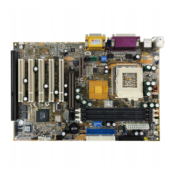
Page 12: 6Vx7-4X Motherboard Layout
6VX7-4X Motherboard 6VX7-4X Motherboard Layout JP30 PS/2 JP16 USB1 LED1 JP19 PGA 370 JP15 VT82C694X 6VX7-4X JP18 BAT1 JP23 PCI1 USB2 PCI2 Creative CT5880 VT82C686A PCI3 PCI4 JP20 BIOS PCI5 JP22 JP24... -
Page 13: Page Index For Cpu Speed Setup/Connectors/Panel And Jumper Definition
6VX7-4X Motherboard Layout Page Page Index for CPU Speed Setup/Connectors/Panel and Jumper Definition CPU Speed Setup Connectors P.17 Game & Audio Port P.17 COM A / COM B / LPT Port P.17 USB1 Connector P.18 PS/2 Keyboard & PS/2 Mouse Connector P.18 JP16 (CPU Fan) P.19... -
Page 14: Cpu Speed Setup
6VX7-4X Motherboard CPU Speed Setup The system bus speed is selectable at 66,100,133MHz and Auto. The user can select the system bus speed (SW1) and change the DIP switch (SW2) selection to set up the CPU speed for 500MHz – 1GHz processor. SW1: O: ON, X: OFF PCI CLK... - Page 15 CPU Speed Setup F For Auto Jumper setting: «Note: 1. If you use 66, 100, 133 MHz CPU, we recommend you to set up your system speed to “Auto” value. 2. We don’t recommend you to set up your system speed to 75,83,112, 124, 140,150 MHz because these frequencies are not the standard specifications for CPU, Chipset and most of the peripherals.
- Page 16 6VX7-4X Motherboard Celeron 566 / 66 MHz FSB Celeron 600 / 66 MHz FSB Celeron 633 / 66 MHz FSB...
- Page 17 CPU Speed Setup Celeron 667 / 66 MHz FSB Celeron 700 / 66 MHz FSB Cyrix III 550 / 100 MHz FSB (Optional) ®...
- Page 18 6VX7-4X Motherboard Cyrix III 533 / 133 MHz FSB (Optional) ® Cyrix III 600 / 133 MHz FSB (Optional) ® !!! 500 / 100MHz FSB 10. Pentium ®...
- Page 19 CPU Speed Setup !!! 550 / 100MHz FSB 11. Pentium ® !!! 600 / 100MHz FSB 12. Pentium ® !!! 650 / 100MHz FSB 13. Pentium ®...
- Page 20 6VX7-4X Motherboard !!! 700 / 100MHz FSB 14. Pentium ® ® !!! 750 / 100MHz FSB 15. Pentium ® !!! 800 / 100MHz FSB 16. Pentium...
- Page 21 CPU Speed Setup ® !!! 850 / 100MHz FSB 17. Pentium ® !!! 533 / 133MHz FSB 18. Pentium ® !!! 600 / 133MHz FSB 19. Pentium...
- Page 22 6VX7-4X Motherboard ® !!! 667 / 133MHz FSB 20. Pentium ® !!! 733 / 133MHz FSB 21. Pentium ® !!! 800 / 133MHz FSB 22. Pentium...
- Page 23 CPU Speed Setup ® !!! 866 / 133MHz FSB 23. Pentium ® !!! 933 / 133MHz FSB 24. Pentium ® !!! 1GHz / 133MHz FSB 25. Pentium...
-
Page 24: Connectors
6VX7-4X Motherboard Connectors Game & Audio Port Game Port MIC In Line Out Line In COM A / COM B / LPT Port LPT Port COM A COM B... -
Page 25: Usb1 Connector
Connectors USB 1 Connector Pin No. Definition USB V0 USB D0- USB D0+ USB V1 USB D1- USB D1+ 5 6 7 8 PS/2 Keyboard & PS/2 Mouse Connector PS/2 Mouse PS/2 Keyboard PS/2 Mouse/ Keyboard Pin No. Definition Data VCC(+5V) Clock... -
Page 26: Jp16: Cpu Fan
6VX7-4X Motherboard JP16: CPU Fan Pin No. Definition +12V SENSE JP15: Power Fan Pin No. Definition +12V... -
Page 27: Jp2: System Fan
Connectors JP2: System Fan Pin No. Definition +12V SENSE ATX Power Pin No. Definition 3,5,7,13,15-17 1,2,11 3.3V 4,6,19,20 +12V -12V Power Good 5V SB stand by+5V PS-ON(Soft On/Off) -
Page 28: Usb 2 Connector
6VX7-4X Motherboard USB 2 Connector Pin No. Definition USB D0- USB D0+ USB D1- USB D1+ IR Connector PIN No. Definition VCC(+5V) IR data input IR data output... -
Page 29: Floppy Port
Connectors Floppy Port Red Line IDE1 (Primary), IDE2(Secondary) Port Red Line IDE 1 IDE 2... -
Page 30: J3 (Ring Power On)
6VX7-4X Motherboard J3: Ring Power On (Internal Modem Card Wake Up) Pin No. Definition Signal J1: Wake On LAN Pin No. Definition +5V SB Signal... -
Page 31: J7 (Tel)
Connectors J7: TEL: The connector is for Modem with internal voice connector Pin No. Definition Signal-In Signal-Out J5: AUX_IN Pin No. Definition AUX-L AUX-R... -
Page 32: J8: Cd Audio Line In
6VX7-4X Motherboard J8: CD Audio Line In Pin No. Definition CD-L CD-R JP5: STR LED Connector & LED1: DIMM LED STR LED Connector External DIMM LED... -
Page 33: Front Usb Port (Optional)
Connectors Front USB Port (Optional) Pin No. Definition 1,4,5,10 3,7,9 USBP0+ USBP0- J11: SM BUS Pin No. Definition SMB CLK SMB DATA... -
Page 34: Panel And Jumper Definition
6VX7-4X Motherboard Panel And Jumper Definition J2: For 2x11 Pins Jumper GN (Green Switch) Open: Normal Operation Close: Entering Green Mode GD (Green LED) Pin 1: LED anode(+) Pin 2: LED cathode(−) HD (IDE Hard Disk Active LED) Pin 1: LED anode(+) Pin 2: LED cathode(−) SPKR (Speaker Connector) Pin 1: VCC(+) -
Page 35: Jp1: Clear Cmos Function
Panel and Jumper Definition JP1: Clear CMOS Function Pin No. Definition 1-2 close Normal (Default) 2-3 close Clear CMOS JP7/JP8/JP18: Onboard AC97 & AMR (Primary or Secondary) Select (AMRà Audio Modem Riser) JP18 Jumper JP18 Function Only AC97 Open Close Close Only AMR Open... -
Page 36: Jp11: Str Enable
6VX7-4X Motherboard JP11: STR Enable Pin No. Definition Open STR Disabled (Default) Close STR Enabled JP20: Onboard Sound Function Selection (Optional) Pin No. Definition Enabled Onboard Sound 1-2 close (Default) 2-3 close Disabled Onboard Sound... -
Page 37: Jp24 (Normal/Recovery) [Optional]
Panel and Jumper Definition JP24: Normal/ Recovery mode (Optional) Pin No. Definition Open Normal Close Recovery JP19: Cyrix CPU Turbo Function (Optional) Pin No. Definition Open Normal Close Turbo... -
Page 38: Jp9: Usb Device Wake Up Selection
6VX7-4X Motherboard JP9: USB Device Wake up Selection Pin No. Definition 1-2 close Normal (Default) Enabled USB Device 2-3 close Wake up (If you want to use “USB KB Wakeup from S3~S5” function, you have to set the BIOS setting “USB KB Wakeup from S3~S5”... -
Page 39: Jp30 (Over Voltage Cpu Speed Up) [Optional]
Panel and Jumper Definition JP22: BIOS Flash ROM Write Protect Pin No. Definition Close BIOS Write Disabled BIOS Write Enabled Open (Default) M Please set Jumper JP22 to “Open” to enabled BIOS write function when you update new BIOS or new device. JP30: Over Voltage CPU Speed Up (Magic Booster) (Optional) (When JP30 set “7-8 Close”, CPU Voltage is rising 10%) Pin No. -
Page 40: J12: Front Panel Jumper (Optional)
6VX7-4X Motherboard J12: Front Panel Jumper (Optional) Pin No. Definition HD LED+ GN LED+ HD LED- PWR LED+ RESET SW Soft ON/OFF 10,12 Green SW IR RX IRTX IR Power BAT1: Battery Danger of explosion if battery is incorrectly replaced. + Replace only with the same or equivalent type recommended by the manufacturer. -
Page 41: Performance List
Performance List Performance List The following performance data list is the testing results of some popular benchmark testing programs. These data are just referred by users, and there is no responsibility for different testing data values gotten by users. (The different Hardware & Software configuration will result in different benchmark testing results.) •... -
Page 42: Block Diagram
6VX7-4X Motherboard Block Diagram 14.318MHz AGP 2X/4X PGA 370 CPU 3.3V DIMM DIMM Sockets Host Bus AGP Bus VT82C694X Ultra DMA ICS 9248DF-39 33/ATA66 IDE Ports 33 MHz PCI Bus 33 MHz ISA Bus 24MHz 48MHz IDE Bus 14.318MHz VT82C686A COM Ports AC’97 -Link Creative... -
Page 43: Suspend To Ram Installation
Suspend to RAM Installation Suspend To RAM Installation A.1 Introduce STR function: Suspend-to-RAM (STR) is a Windows 98 ACPI sleep mode function. When recovering from STR (S3) sleep mode, the system is able, in just a few seconds, to retrieve the last “state” of the system before it went to sleep and recover to that state. - Page 44 6VX7-4X Motherboard Step 2: (If you want to use STR Function, please set jumper JP11 Closed.) Pin No. Definition Open STR Disabled (Default) Close STR Enabled Step 3: Power on the computer and as soon as memory counting starts, press <Del>. You will enter ACPI Sleep BIOS Setup.
- Page 45 Suspend to RAM Installation A.3 How to put your system into STR mode? There are two ways to accomplish this: Choose the “Stand by” item in the “Shut Down Windows” area. A. Press the “Start” button and then select “Shut Down” B.
- Page 46 6VX7-4X Motherboard Define the system ”power on” button to initiate STR sleep mode: A. Double click “My Computer” and then “Control Panel” B. Double click the “ Power Management” item.
- Page 47 Suspend to RAM Installation C. Select the “Advanced” tab and “Standby” mode in Power Buttons. Step 4: Restart your computer to complete setup. Now when you want to enter STR sleep mode, just momentarily press the “Power on” button.. A.4 How to recover from the STR sleep mode? There are five ways to “wake up”...
- Page 48 6VX7-4X Motherboard A.5 Notices: In order for STR to function properly, several hardware and software requirements must be satisfied: Your ATX power supply must comply with the ATX 2.01 specification (provide more than 720 mA 5V Stand-By current). Your SDRAM must be PC-100 compliant. Jumper JP5 is provided to connect to the STR LED in your system chassis.
-
Page 49: Memory Installation
Memory Installation Memory Installation The motherboard has 3 dual inline memory module (DIMM) sockets. The BIOS will automatically detects memory type and size. To install the memory module, just push it vertically into the DIMM Slot .The DIMM module can only fit in one direction due to the two notch. Memory size can vary between sockets. -
Page 50: Page Index For Bios Setup
6VX7-4X Motherboard $ Page Index for BIOS Setup Page The Main Menu P.45 Standard CMOS Setup P.47 BIOS Features Setup P.50 Chipset Features Setup P.52 Power Management Setup P.55 PNP/ PCI Configuration P.58 Load BIOS Defaults P.60 Load Setup Defaults P.61 Integrated Peripherals P.62... - Page 51 BIOS Setup BIOS Setup BIOS Setup is an overview of the BIOS Setup Program. The program that allows users to modify the basic system configuration. This type of information is stored in battery-backed CMOS RAM so that it retains the Setup information when the power is turned off. ENTERING SETUP Power ON the computer and press <Del>...
-
Page 52: The Main Menu
6VX7-4X Motherboard GETTING HELP Main Menu The on-line description of the highlighted setup function is displayed at the bottom of the screen. Status Page Setup Menu / Option Page Setup Menu Press F1 to pop up a small help window that describes the appropriate keys to use and the possible selections for the highlighted item. - Page 53 BIOS Setup • Chipset Features Setup This setup page includes all the items of chipset special features. • Power Management Setup This setup page includes all the items of Green function features. • PnP/PCI Configurations This setup page includes all the configurations of PCI & PnP ISA resources. •...
-
Page 54: Standard Cmos Setup
6VX7-4X Motherboard Standard CMOS Setup The items in Standard CMOS Features Menu (Figure 2) are divided into 9 categories. Each category includes no, one or more than one setup items. Use the arrows to highlight the item and then use the <PgUp> or <PgDn> keys to select the value you want in each item. AMIBIOS SETUP –... - Page 55 BIOS Setup • Time The times format in <hour> <minute> <second>. The time is calculated base on the 24-hour military-time clock. For example, 1 p.m. is 13:00:00. • Primary Master, Slave / Secondary Master, Slave The category identifies the types of hard disk from drive C to F that has been installed in the computer.
- Page 56 6VX7-4X Motherboard • Boot Sector Virus Protection If it is set to enable, the category will flash on the screen when there is any attempt to write to the boot sector or partition table of the hard disk drive. The system will halt and the following error message will appear in the mean time.
-
Page 57: Bios Features Setup
BIOS Setup BIOS Features Setup AMIBIOS SETUP – BIOS FEATURES CMOS SETUP ( C ) 1999 American Megatrends, Inc. All Rights Reserved 1st Boot Device :Floppy 2nd Boot Device :IDE-0 3rd Boot Device :CDROM S.M.A.R.T for Hard Disks :Disabled BootUp Num-Lock Floppy Drive Seek :Disabled Password Check... - Page 58 6VX7-4X Motherboard • Boot Up Num-Lock Keypad is number keys. (Default Value) Keypad is arrow keys. • Floppy Drive Seek During POST, BIOS will determine if the floppy disk drive installed is 40 or 80 tracks. 360 type is 40 tracks while 720 , 1.2 and 1.44 are all 80 tracks. Enabled BIOS searches for floppy disk drive to determine if it is 40 or 80 tracks.
-
Page 59: Chipset Features Setup
BIOS Setup Chipset Features Setup AMIBIOS SETUP –CHIPSET FEATURE CMOS SETUP ( C ) 1999 American Megatrends, Inc. All Rights Reserved *** DRAM Timing *** Top Performance :Disabled SDRAM Timing by SPD :Disabled SDRAM CAS# Latency DRAM Frequency :Auto C2P Concurrency & Master :Enabled DRAM Integrity Mode :Disabled... - Page 60 6VX7-4X Motherboard • C2P Concurrency & Master Enabled C2P Concurrency & Master. (Default Value) Enabled Disabled Disabled C2P Concurrency & Master. • DRAM Integrity Mode For 72 bit ECC type DIMM Modle. Normal Setting. (Default Value) Disabled • AGP Mode Set AGP Mode is 4X.
- Page 61 BIOS Setup • USB Controller USB Port 0&1 USB Controller for USB Port 0&1. USB Port 2&3 USB Controller for USB Port 2&3. All USB Port USB Controller for All USB Port. (Default Value) Disabled USB Controller Function Disabled. • USB Legacy Support Keyboard Set USB Legacy Support Keyboard.
- Page 62 6VX7-4X Motherboard Power Management Setup AMIBIOS SETUP –POWER MANAGEMENT SETUP ( C ) 1999 American Megatrends, Inc. All Rights Reserved ACPI Sleep Type :S1/POS PME Event Wake up :Enabled USB KB Wakeup From S3~S5 :Disabled RTC Alarm Power On :Disabled Video Power Down Mode :Stand By RTC Alarm Date...
- Page 63 BIOS Setup • Suspend Time Out (Minute.) Disabled Suspend Time Out Function. (Default Value) Disabled Enabled Suspend Time Out after 1min. Enabled Suspend Time Out after 2min. Enabled Suspend Time Out after 4min. Enabled Suspend Time Out after 8min. Enabled Suspend Time Out after 10min. Enabled Suspend Time Out after 20min.
- Page 64 6VX7-4X Motherboard • MODEM Use IRQ Set MODEM Use IRQ to NA. Set MODEM Use IRQ to 3. Set MODEM Use IRQ to 4. (Default Value) Set MODEM Use IRQ to 5. Set MODEM Use IRQ to 7. • Modem Ring On/Wake On Lan Disabled Disabled Modem Ring On/Wake On Lan.
- Page 65 BIOS Setup PnP/PCI Configurations AMIBIOS SETUP –PNP/PCI CONFIGURATION SETUP ( C ) 1999 American Megatrends, Inc. All Rights Reserved Plug and Play Aware O/S Reset Configuration Data VGA Boot From :AGP PCI VGA Palette Snoop :Disabled DMA Channel 0 :PnP DMA Channel 1 :PnP DMA Channel 3...
- Page 66 6VX7-4X Motherboard • DMA Channel (0,1,3,5,6,7) The resource is used by PnP device. ISA / EISA The resource is used by ISA / EISA device (PCI or ISA). • IRQ (3,4,5,7, 9,10,11,14,15) PCI/PnP The resource is used by PCI/PnP device. ISA / EISA The resource is used by ISA / EISA device (PCI or ISA).
-
Page 67: Power Management Setup
BIOS Setup Load BIOS Defaults AMIBIOS SIMPLE SETUP UTILITY-VERSION 1.22 ( C ) 1999 American Megatrends, Inc. All Rights Reserved STANDARD CMOS SETUP INTEGRATED PERIPHERALS BIOS FEATURES SETUP HARDWARE MONITOR SETUP CHIPSET FEATURES SETUP SUPERVISOR PASSWORD POWER MANAGEMENT SETUP USER PASSWORD Load BIOS Defaults (Y/N)? N PNP/PCI CONFIGURATION IDE HDD AUTO DETECTION... -
Page 68: Load Setup Defaults
6VX7-4X Motherboard Load Setup Defaults AMIBIOS SIMPLE SETUP UTILITY-VERSION 1.22 ( C ) 1999 American Megatrends, Inc. All Rights Reserved STANDARD CMOS SETUP INTEGRATED PERIPHERALS BIOS FEATURES SETUP HARDWARE MONITOR SETUP CHIPSET FEATURES SETUP SUPERVISOR PASSWORD POWER MANAGEMENT SETUP USER PASSWORD Load SETUP Defaults (Y/N)? N PNP/PCI CONFIGURATION IDE HDD AUTO DETECTION... -
Page 69: Integrated Peripherals
BIOS Setup Integrated Peripherals AMIBIOS SETUP –INTEGRATED PERIPHERAL ( C ) 1999 American Megatrends, Inc. All Rights Reserved OnBoard IDE :Both Game Port(200h-207h) :Enabled OnBoard FDC :Auto OnBoard Serial Port 1 :Auto OnBoard Serial Port 2 :Auto Serial Port 2 Mode :Normal Duplex Mode :N/A... - Page 70 6VX7-4X Motherboard • OnBoard Serial Port 2 BIOS will automatically setup the port 2 address. (Default Value) Auto 3F8/COM1 Enable onBoard Serial port 2 and address is 3F8. 2F8/COM2 Enable onBoard Serial port 2 and address is 2F8. 3E8/COM3 Enable onBoard Serial port 2 and address is 3E8. 2E8/COM4 Enable onBoard Serial port 2 and address is 2E8.
- Page 71 BIOS Setup • Parallel Port IRQ Set Parallel Port IRQ is 7. Set Auto to parallel Port IRQ DMA Channel. (Default Value) Auto Set Parallel Port IRQ is 5. • OnBoard AC’97 Audio Set OnBoard AC’97 Audio to Auto. (Default Value) Auto Disabled Disabled OnBoard AC’97 Audio.
- Page 72 6VX7-4X Motherboard • MUP-401 I/O Address Set MUP-401 I/O Address is 330h-333h. (Default Value) 330h-333h 300h-303h Set MUP-401 I/O Address is 300h-303h. 310h-313h Set MUP-401 I/O Address is 310h-313h. 320h-323h Set MUP-401 I/O Address is 320h-323h. • FM Port (388h-38Bh) Disabled FM Port (388h-38Bh).
- Page 73 BIOS Setup Hardware Monitor AMIBIOS SETUP –HARDWARE MONITOR ( C ) 1999 American Megatrends, Inc. All Rights Reserved ACPI Shut Down Temp. :Disabled Current CPU Temp. :36°C/96°F Current System Temp. :28°C/82°F Case Status :Closed Current CPU Fan Speed :5487 RPM Current System Fan Speed :0 RPM Vcore...
- Page 74 6VX7-4X Motherboard • Current CPU Temp. (°C / °F) Detect CPU Temperature automatically. • Current System Temp. (°C / °F) Detect System Temperature automatically. • Case Status If the case is closed, “Case Status” will show “Closed”. If the case have been opened, “Case Opened” will show “Open”. •...
-
Page 75: Hardware Monitor Setup
BIOS Setup Set Supervisor / User Password When you select this function, the following message will appear at the center of the screen to assist you in creating a password. AMIBIOS SIMPLE SETUP UTILITY-VERSION 1.22 ( C ) 1999 American Megatrends, Inc. All Rights Reserved STANDARD CMOS SETUP INTEGRATED PERIPHERALS BIOS FEATURES SETUP... -
Page 76: Ide Hdd Auto Detection
6VX7-4X Motherboard IDE HDD AUTO Detection AMIBIOS SETUP – STANDARD CMOS SETUP ( C ) 1999 American Megatrends, Inc. All Rights Reserved Date (mm/dd/yyyy) : Tue Feb 17, 2000 Time (hh/mm/ss) : 10:36:24 TYPE SIZE CYLS HEAD PRECOMP LANDZ SECTOR MODE Pri Master :Auto Pri Slave... -
Page 77: Save To Cmos And Exit
BIOS Setup Save & Exit Setup AMIBIOS SIMPLE SETUP UTILITY-VERSION 1.22 ( C ) 1999 American Megatrends, Inc. All Rights Reserved STANDARD CMOS SETUP INTEGRATED PERIPHERALS BIOS FEATURES SETUP HARDWARE MONITOR SETUP CHIPSET FEATURES SETUP SUPERVISOR PASSWORD POWER MANAGEMENT SETUP USER PASSWORD SAVE to CMOS and EXIT(Y/N)? Y PNP/PCI CONFIGURATION... -
Page 78: Exit Without Saving
6VX7-4X Motherboard Exit Without Saving AMIBIOS SIMPLE SETUP UTILITY-VERSION 1.22 ( C ) 1999 American Megatrends, Inc. All Rights Reserved STANDARD CMOS SETUP INTEGRATED PERIPHERALS BIOS FEATURES SETUP HARDWARE MONITOR SETUP CHIPSET FEATURES SETUP SUPERVISOR PASSWORD POWER MANAGEMENT SETUP USER PASSWORD Quit without saving (Y/N) ? N PNP/PCI CONFIGURATION IDE HDD AUTO DETECTION... -
Page 79: Appendix
Appendix Appendix Appendix A : VIA Chipsets Driver Installation A.VIA 4 in 1 Service Pack Utility: Insert the support CD that came with your motherboard into your CD-ROM driver or double –click the CD driver icon in My Computer to bring up the screen. 1.Click “VIA 4in 1 Service Pack 2.Click “Next”. - Page 80 6VX7-4X Motherboard 8.Click “Next”. 7.Click “Next”. 10.Click “Finish” to restart computer. 9.Click “Next”. (10)
- Page 81 Appendix Appendix B: VIA Sound Driver A. AC’97 Audio Driver: Insert the support CD that came with your motherboard into your CD-ROM driver or double –click the CD driver icon in My Computer to bring up the screen. Audio 2.Click “Next”. 1.Click “AC’97 Audio Driver”...
- Page 82 6VX7-4X Motherboard Appendix C: Creative Sound Driver Installation (Optional) Insert the support CD that came with your motherboard into your CD-ROM driver or double –click the CD driver icon in My Computer to bring up the screen. Audio 2.Click “OK”. 1.Click “Creative 5880 Sound Driver”.
- Page 83 Appendix 7.Click “Finish” to restart computer.
- Page 84 C:\utility\ AWDFlash or AMIFlash <filename of the BIOS binary file intended for flashing> ü Once the process is finished, reboot the system MNote: Please download the newest BIOS from our website (www.gigabyte.com.tw) or contact your local dealer for the file.
- Page 85 Appendix Appendix E: Acronyms Acro. Meaning ACPI Advanced Configuration and Power Interface POST Power-On Self Test Local Area Network Extended Capabilities Port Advanced Power Management Direct Memory Access Megahertz ESCD Extended System Configuration Data Central Processing Unit Symmetric Multi-Processing Universal Serial Bus Operating System Error Checking and Correcting Integrated Dual Channel Enhanced...
- Page 86 6VX7-4X Motherboard Acro. Meaning Peripheral Component Interconnect RIMM Rambus in-line Memory Module Dual Retention Mechanism Industry Standard Architecture Memory Translator Hub CRIMM Continuity RIMM...