Table of Contents
Advertisement
Quick Links
Before using this product, be sure to read "Read this first!" (pages 5, 27 to 31).
ENGLISH
This manual contains information excerpted from the Operating Instructions and the Installation Instructions.
<Basics>
For more information, please visit the Panasonic website (http://pro-av.panasonic.net/manual/en/index.html), and
refer to the Operating Instruction (PDF).
Avant d'utiliser cet appareil, assurez-vous de lire la section « Lire ces informations en premier ! ».
FRANÇAIS
Pour de plus amples informations, visiter le site Web de Panasonic (http://pro-av.panasonic.net/manual/en/index.
html) et consulter le mode d'emploi (PDF).
Antes de usar este producto, asegúrese de leer "Lea este documento en primer lugar!".
ESPAÑOL
Si desea obtener más información, visite el sitio web de Panasonic (http://pro-av.panasonic.net/manual/en/index.
html) y consulte las instrucciones de funcionamiento (PDF).
Bitte lesen Sie sorgfältig die „Bitte lesen Sie zuerst diesen Hinweis!" vor der Nutzung dieses Produkts.
DEUTSCH
Weitere Informationen finden Sie auf der Panasonic-Webseite (http://pro-av.panasonic.net/manual/en/index.html)
und in der Bedienungsanleitung (PDF).
Prima di utilizzare il prodotto, assicurarsi di leggere "Leggere prima quanto segue!".
ITALIANO
Per maggiori informazioni, per favore visitare il sito web Panasonic (http://pro-av.panasonic.net/manual/en/index.
html), e fare riferimento alle istruzioni per l'uso (PDF).
Перед использованием данного прибора ознакомьтесь с информацией в разделе «Прочитайте
нижеследующее до начала эксплуатации!».
PУССКИЙ
Для получения дополнительной информации посетите веб-сайт Panasonic (http://pro-av.panasonic.net/
manual/en/index.html), а также обратитесь кинструкции по эксплуатации (PDF).
Before operating this product, please read the instructions carefully and save this manual for future use.
CX1217TY0 -FJ
Printed in China
Operating Instructions
Installation Instructions provided
AW‑UN70WPC
Model No.
AW‑UN70KPC
Model No.
AW‑UN70WE
Model No.
AW‑UN70KE
Model No.
<Basics>
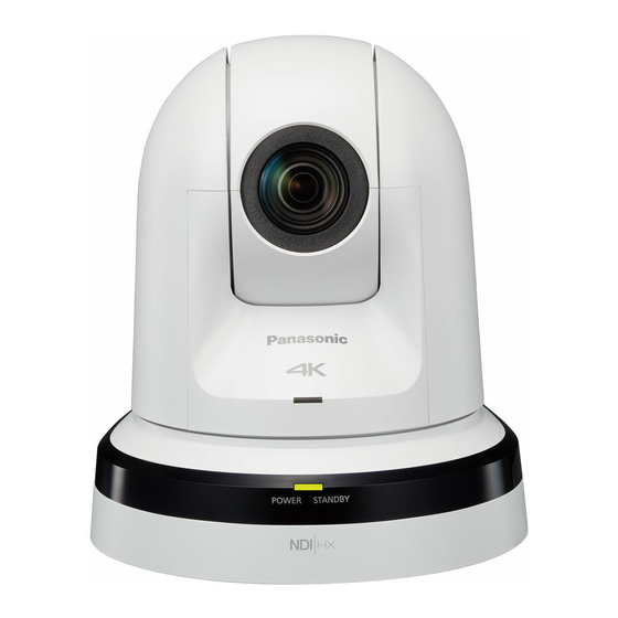
4K Integrated Camera
ENGLISH
DVQX1544ZA
Advertisement
Table of Contents

Related Manuals for Panasonic AW-UN70WPC


Summary of Contents for Panasonic AW-UN70WPC
- Page 1 Avant d’utiliser cet appareil, assurez-vous de lire la section « Lire ces informations en premier ! ». FRANÇAIS Pour de plus amples informations, visiter le site Web de Panasonic (http://pro-av.panasonic.net/manual/en/index. html) et consulter le mode d’emploi (PDF). Antes de usar este producto, asegúrese de leer “Lea este documento en primer lugar!”.
- Page 2 Ελληνικά σημαντικές ειδοποιήσεις που αφορούν το προϊόν σας, επισκεφτείτε τον ιστότοπο που ακολουθεί. Besök följande webbplats för säkerhetsinformation Svenska och viktiga meddelanden om produkten. A termékkel kapcsolatos biztonsági információkért Magyar és fontos értesítésekért látogasson el az alábbi weboldalra. http://pro-av.panasonic.net/manual/en/index.html...
- Page 3 P. 110 of the <Operations and Settings> is performed. At least three (3) years from delivery of this product, Panasonic will give to any third party who contacts us at the contact information provided below, for a charge no more than our cost of physically performing source code distribution, a complete machine-readable copy of the corresponding source code covered under GPL V2.0 or...
-
Page 4: Table Of Contents
Contents Installation Instructions Read this first! Connections Connecting an NDI|HX compatible switcher Installation precautions Connecting a controller (AW-RP50/AW-RP120) How to install and connect the unit (IP connection example) When using the WV-Q105A (optional accessory) System example 1 (connection with commercially available controller, RS-232C daisy-chain Removing the camera connection) -
Page 5: Installation Instructions
To prevent injury, this apparatus must be securely This camera intended for use only with the Mount attached to the floor/wall in accordance with the Bracket enclosed with the unit and Panasonic Direct installation instructions. Ceiling Mount Bracket, WV-Q105A. Use with other apparatus is capable of resulting in instability causing possible injury. -
Page 6: Installation Precautions
Installation precautions Panasonic does not accept any responsibility for accident or damage during installation if procedure in this manual is not followed. To installation personnel Read the “Installation Instructions” thoroughly and then perform the operation correctly and safely. Also, always read the “Read this first!” (page 5) of this manual as they contain important information. - Page 7 Installation precautions (continued) Be absolutely sure to use the specified brackets and Power switch screws to install the camera. The unit does not have a power switch. The power turns ● Do not mount the unit by employing any methods other on when its power plug is connected to a power outlet.
-
Page 8: How To Install And Connect The Unit
How to install and connect the unit Be absolutely sure to read through the “Read this first!” (page 5) and “Installation precautions” (pages 6 to 7). The procedure given here is for the kind of installation where the unit is suspended from an overhead surface, but the same steps are followed for a stand-alone installation. - Page 9 How to install and connect the unit (continued) Mount the mount bracket onto the installation surface. ● Use the bracket mounting screws [M4, bind-head: 10 mm (13/32 inches) long] supplied with the unit. ● For proper clamping torque, securely attach the screws using the specified tools. Screw diameter Clamping torque 1.47 N ·...
- Page 10 How to install and connect the unit (continued) Mount the unit. ● Align the position of the hole for checking the positioning with the status display lamp. ● Align the holes on the camera main unit used to insert the bottom panel with the protrusions on the mount bracket used for inserting the camera, push the camera to the bracket firmly, and rotate the main unit by about 15 degrees in the direction of the arrow.
- Page 11 How to install and connect the unit (continued) Connect the rear panel connectors. Anchor the AC adaptor cable in place using the cable clamp. ● How to secure the AC adaptor cable A Loosely secure the cable clamp. Cable clamp AC adaptor cable LAN cable RS‑232C cable...
-
Page 12: When Using The Wv-Q105A (Optional Accessory)
How to install and connect the unit (continued) ■ When using the WV‑Q105A (optional accessory) It is recommended that you provide an inspection opening or other such space for access purposes in the area near where the equipment is installed in order to facilitate installation and the wiring connections work. Before mounting the mount bracket, check that the installation location is strong enough to withstand the total mass (approx. - Page 13 How to install and connect the unit (continued) When installing the unit on a wall (installation example) Before proceeding, fashion an L‑shaped mounting fixture, and attach the fixture securely to the wall where the unit will be installed. IMPORTANT ● Before installing the unit, check that the surface of the wall where the unit will be installed is strong enough to bear not only the total weight (approx.
-
Page 14: Removing The Camera
Removing the camera Turn off the circuit breaker and power. Disconnect the cables. Disconnect the power cable, video cable, and control cable, etc. Remove the main unit mounting screw used to secure the unit and mount bracket. Push the unit (A). Turn it approximately 15 degrees away from the installed position (B), and remove it (C). -
Page 15: Stand-Alone Installation (When The Mount Bracket Is Going To Be Used)
Stand‑alone installation (when the mount bracket is going to be used) The same steps are followed as for the kind of installation where the unit is suspended from an overhead surface (pages 8 to 11). Check the mounting space. Note ●... - Page 16 Stand‑alone installation (when the mount bracket is going to be used) (continued) Check the mounting. Connect the rear panel connectors. ● How to secure the AC adaptor cable A Loosely secure the cable clamp. Coaxial cable (for G/L IN) Cable clamp SDI cable LAN cable (for RS‑422)
-
Page 17: Stand-Alone Installation (When The Mount Bracket Is Not Going To Be Used)
Stand‑alone installation (when the mount bracket is not going to be used) ■ When installing the unit on a desktop Place the unit flat on the surface. Notes ● Install the unit in a stable location which will not be susceptible to shaking. If the unit is installed in a location which is susceptible to shaking, this will cause the unit’s images to shake in turn. -
Page 18: Connections
Connections ■ Connecting an NDI|HX compatible switcher AW‑UN70 AW‑UN70* Supplied AC adaptor LAN cable Switching hub NDI|HX compatible switcher External DC Remote Camera Controller power supply AW‑RP120 *: The AC adaptor provided with the unit is not shown Monitor Monitor in the above figure. -
Page 19: Connecting A Controller (Aw-Rp50/Aw-Rp120)
Connections (continued) ■ Connecting a controller (AW‑RP50/AW‑RP120) (IP connection example) LAN cable Pan‑tilt head / camera control signal AW‑UN70 Remote Camera Controller HDMI/SDI signal AW‑RP50 SIGNAL GND POWER TO PAN/TILT HEAD 12V IN TALLY/GPI BOOT Monitor Supplied AC adaptor Supplied AC adaptor Remote Camera Controller AW‑RP120 External DC... -
Page 20: System Example
Connections (continued) ■ System example 1 (connection with commercially available controller, RS‑232C daisy‑chain connection) AW‑UN70* Up to 7 Commercially available controller RS‑232C connector RS‑232C Supplied AC adaptor Supplied AC adaptor Supplied AC adaptor connector *: You can connect up to seven cameras to a single controller. ●... -
Page 21: System Example
Connections (continued) ■ System example 2 (connection with commercially available controller, RS‑422 connection) AW‑UN70 RS‑422 communication connector Commercially available controller Supplied AC adaptor ● Configure the service switches at the bottom of the unit. For details on the service switches, see “Service switch settings” (page 42). Camera address Set to AUTO or 1 to 7. -
Page 22: System Example 3 (Serial Control)
Connections (continued) ■ System example 3 (serial control) AW‑UN70 AW‑UN70* RS‑422 connector Supplied AC adaptor HDMI/SDI converters (commercially available) Pan‑tilt head / camera control signal (LAN cable (straight cable)) Monitor 1 Monitor 2 Monitor Monitor Supplied AC System tally adaptor Compact Live Switcher AW‑HS50 External DC... -
Page 23: System Example 4 (Ip Control)
Connections (continued) ■ System example 4 (IP control) AW‑UN70 AW‑UN70* IP video display Mobile terminal Supplied AC adaptor HDMI/SDI converters (commercially available) Wireless access point LAN cable IP video display Monitor 2 Switching hub Monitor 1 LAN cable (straight cable) Personal computer Monitor Monitor... -
Page 24: System Example 5 (Infrared Output Connection)
Connections (continued) ■ System example 5 (infrared output connection) You can point the infrared remote control of a commercially available controller toward the camera to operate it. Remote camera control signal RS‑232C cable Commercially available controller (including infrared remote control signals) AW‑UN70 RS‑232C connector... -
Page 25: System Example 7 (Usb Connection, Web Camera)
Connections (continued) ■ System example 7 (USB connection, Web camera) AW‑UN70 Communication software (optional accessory) Microphone Supplied AC adaptor USB cable (A‑mini B type) Personal computer ● Use a USB cable that is compatible with the USB 2.0 specification. Connect a mini B connector to the unit. ●... -
Page 26: Appearance
Appearance Unit: mm (inch) 66 (2-19/32) 62 (2-7/16) 160 (6-5/16) 99 (3-29/32) 179 (7-3/64) 80 (3-5/32) 77 (3-1/32) 166 (6-17/32) -
Page 27: Read This First! (For Aw-Un70Wpc, Aw-Un70Kpc)
Canada. Operation at a voltage other than 120 V AC may require the use of a different AC plug. Please contact either a local or foreign Panasonic authorized service center for assistance in selecting an alternate AC plug. indicates safety information. - Page 28 Read this first! (For AW‑UN70WPC, AW‑UN70KPC) (continued) FCC NOTICE (USA) This device complies with part 15 of the FCC Rules. Operation is subject to the following two conditions: (1) This device may not cause harmful interference, and (2) this device must accept any interference received, including interference that may cause undesired operation.
-
Page 29: Read This First! (For Aw-Un70We, Aw-Un70Ke)
Read this first! (For AW‑UN70WE, AW‑UN70KE) WARNING: CAUTION: • To reduce the risk of fire or electric shock, do not In order to maintain adequate ventilation, do not expose this equipment to rain or moisture. install or place this unit in a bookcase, built-in cabinet •... - Page 30 3. Change the connection method used for the apparatus. 4. Connect the apparatus to another power outlet where the power is not shared by any other appliances. Інформація для покупця Виробник: Panasonic Corporation Панасонік Корпорейшн Адреса виробника: Kadoma, Osaka, Japan Кадома, Осака, Японія...
- Page 31 Figure A Figure B Fuse Fuse (5 ampere) (5 ampere) indicates safety information. Manufactured by: Panasonic Corporation, Osaka, Japan Importer’s name and address of pursuant to EU rules: Panasonic Marketing Europe GmbH Panasonic Testing Centre Winsbergring 15, 22525 Hamburg, Germany...
-
Page 32: Before Use
® viewing the camera images on the screen. Microsoft Windows 7 Professional SP1 ® ® ● Connection with a Panasonic camera controller is also 64-bit/32-bit * Windows Internet Explorer 8.0 / 9.0 / ® ® possible via Panasonic’s proprietary serial communication 10.0 / 11.0 *... -
Page 33: Disclaimer Of Warranty
IN NO EVENT SHALL Panasonic Corporation BE LIABLE ● After accessing the unit as an administrator, be sure to TO ANY PARTY OR ANY PERSON, EXCEPT FOR close all web browsers. -
Page 34: Characteristics
30× zoom (22× in 4K mode) while maintaining HD and pan-tilt head unit systems currently available from quality. Panasonic Corporation so that an existing system can be ● The unit is equipped with functions that allow clean used to advantage to put together a system that is even and clear reproduction of images in a wide range of more flexible. - Page 35 Easy connections and settings courtesy of IP control ● Up to a hundred units can be operated by IP connection Built‑in ND filter from a Panasonic controller (AW-RP50, AW-RP120 and ● Built-in ND filter with 4 positions (Through, 1/4, 1/16, AK-HRP200).
-
Page 36: Controller Supported
● AK‑HRP200: Ver 5.10‑00‑0.00 or later ● If the version older, an upgrade is required. For details on upgrading, visit the support page on the following website. http://pro-av.panasonic.net/ ● For details on AW-RP555 and AW-RP655, refer to page 23 in the <Operations and Settings>. Accessories Check that the following accessories are present and accounted for. -
Page 37: Operating Precautions
Operating precautions Shoot under the proper lighting conditions. When using the automatic functions ● If “Full Auto” has been selected as the setting for Scene To produce pictures with eye-pleasing colors, shoot under the proper lighting conditions. on the camera menu, for example, all the auto settings The pictures may not appear with their proper colors when will be turned on, and manual operations will no longer be shooting under fluorescent lights. - Page 38 Operating precautions (continued) Color bars Do not point the camera directly at the sun or a laser beam no matter whether it is turned on or not. Color bars are used to adjust the color phase, and the widths and positions of these bars may differ from other models. Taking images of the sun, laser beams, or other brightly lit subjects for prolonged periods of time may damage the MOS sensor.
- Page 39 Concerning the wireless remote control (optional accessory) ● If the unit is installed near fluorescent lights, plasma The unit can be operated by remote control using a wireless remote control (model number: AW‑RM50G) monitors or other such products or if the unit is purchased separately.
-
Page 40: Parts And Their Functions
Parts and their functions ■ Camera unit Mount bracket for installation surface (supplied accessory) Mount this bracket onto the installation surface, and then attach the camera main unit to the bracket. Drop‑prevention wire Pull out the wire from the bottom panel of the camera main unit, and attach it to the hook of the mount bracket. - Page 41 Parts and their functions (continued) LAN connector for IP control [LINK/ACT] RS‑422 connector [RS‑422] This LAN connector (RJ-45) is connected when exercising This RS-422 connector (RJ-45) is connected when IP control over the unit from an external device. exercising serial control over the unit from an external Use a cable with the following specifications for the device.
- Page 42 When this is set to ON, standard serial communication is 1080/25p 576/50i — enabled. 1080/50i 576/50i 1080/50i When this is set to OFF, Panasonic’s proprietary serial 1080/25PsF 576/50i 1080/50i 720/50p 576/50i 720/50p communication is enabled. ● External synchronization is performed using the SDI video (3) SW5: Maintenance switch signal.
-
Page 43: Wireless Remote Controller (Optional Accessory)
Parts and their functions (continued) ■ Wireless remote controller MENU button Each time this is pressed for 2 seconds, operation (optional accessory) switches between displaying the unit’s camera menu and exiting the camera menu. When it is pressed quickly (for less than 2 seconds) while a menu is displayed, the setting change is canceled. - Page 44 Parts and their functions (continued) PRESET/LIMIT button M/FOCUS button This is used to register the settings in the preset This is used when manually adjusting the lens focus. memories or set or release the limiters. The FOCUS buttons ([F] and [N]) are used when When a preset memory call button is pressed while the performing the actual adjustment.
-
Page 45: Setting The Remote Control Ids
Setting the remote control IDs The wireless remote control (optional accessory) is capable of operating up to four units. IDs are used to set which units are selected when the [CAM1], [CAM2], [CAM3] and [CAM4] buttons on the wireless remote control have been pressed. ●... -
Page 46: Network Settings [When Using Windows]
Easy IP Setup Software supplied. You can obtain Easy IP Setup Software (EasyIPSetup.exe) by downloading it from the following website. http://pro-av.panasonic.net/ To establish the settings for a multiple number of units, the settings must be selected for each camera involved. -
Page 47: Installing The Plug-In Viewer Software
Network settings [When using Windows] (continued) ■ Installing the plug‑in viewer Input the network items, and click the [Save] button. software To view IP images from the unit on a web browser, the “Network Camera View 4S” plug-in viewer software (ActiveX ®... -
Page 48: User Authentication
Network settings [When using Windows] (continued) ■ User authentication User name and password management • Use a combination of characters and numbers that is The unit can be configured to allow access from the difficult to guess. internet. To prevent infringement of privacy and personality Avoid using a string of the same characters, such as rights, information leaks, and other issues concerning “11111”, birth dates, or telephone numbers. -
Page 49: Troubleshooting
Troubleshooting ● Operation Reference Symptom Cause and remedial action pages ● Is the AC adaptor securely connected to the AC outlet? ––– ● If the power plug of the AC adaptor connected properly? ––– ● Is the network cable for the PoE+ (IEEE802.3at compliant) P.35 No power compatible power supply device and the unit connected properly? - Page 50 Troubleshooting (continued) Reference Symptom Cause and remedial action pages ● Is the unit connected to the controller properly? P.19 to 24 Refer to the Operating Instructions of the controller. ● The user authorization must be set to OFF when the AW‑RP50, <Operations and AW‑RP120, and AK‑HRP200 remote camera controllers are Settings>...
-
Page 51: Specifications
Specifications ■ INPUT Power requirements: 12 V (Supplied AC adaptor) Power: DC 12 V IN, 42 V to 57 V (PoE+ power supply) PoE+ (IEEE802.3at compliant) Current consumption: 1.3 A (Supplied AC adaptor) Mic/line input: Stereo mini-jack (ø3.5 mm) 0.5 A (PoE+ power supply) Input impedance: Approx. - Page 52 Specifications (continued) ■ FUNCTIONS AND PERFORMANCE Electronic shutter speed: During Full Auto: [Camera unit] 59.94 Hz 1/60 to 1/2000 (Auto Slow Shutter: Off) 1/30 to 1/2000 (Auto Slow Shutter: On) Imaging sensors: 1/2.3-type MOS 50 Hz 1/50 to 1/2000 (Auto Slow Shutter: Off) 1/25 to 1/2000 (Auto Slow Shutter: On) Lens: Motorized 20×...
- Page 53 Specifications (continued) [USB connection] [Pan‑tilt head unit] ● This may vary depending on the operating environment. Installation method: Stand-alone (Desktop) or Video output: USB Video Class Ver1.0 suspended (Hanging) ● To ensure safety, the unit must be Video compression format: secured using the mount bracket Motion JPEG supplied.
- Page 54 Specifications (continued) ■ [SD card recording] AC adaptor MPEG-4 AVC file standard compliant (.MP4) Video compression format: Input: 100 V to 240 V, 1.2 A, 50/60 Hz MPEG-4 AVC/H.264 High Profile Output: DC 12 V, 3.0 A, 36 W Audio compression format: indicates safety information.
-
Page 55: Index
Index AC adaptor (Supplied) ..........36, 54 Output format ..............52 AC adaptor cable ............11, 16 AK-HRP200 ..............36 AW-HS50 ..............22, 23 PoE+ ................. 35 AW-RM50G ..............36, 39 PoE+ compatible switching hub ........24 AW-RP50 .............. 19, 23, 36 Power cable .............. - Page 56 Note for the battery symbol (bottom symbol): This symbol might be used in combination with a chemical symbol. In this case it complies with the requirement set by the Directive for the chemical involved. Web Site: http://www.panasonic.com © Panasonic Corporation 2017...