Table of Contents
Advertisement
Quick Links
6BXC
TABLE OF CONTENTS
1.
1.1. PREFACE ...................................................................................................... 1-1
1.2. KEY FEATHERS............................................................................................ 1-1
1.3. PERFORMANCE LIST .................................................................................. 1-2
1.4. BLOCK DIAGRAM......................................................................................... 1-3
1.5. INTRODUCE THE PENTIUM ® II PROCESSOR & AGP............................. 1-4
1.6. WHAT IS AGP?.............................................................................................. 1-6
2.
2.1. HARDWARE .................................................................................................. 2-1
2.2. SOFTWARE................................................................................................... 2-2
2.3. ENVIRONMENT ............................................................................................ 2-2
3.
3.1. UNPACKING.................................................................................................. 3-1
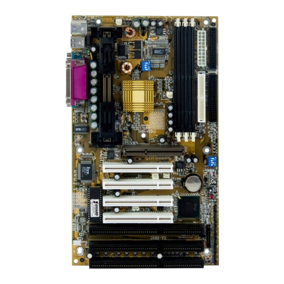
3.2. MAINBOARD LAYOUT ................................................................................. 3-2
3.3. QUICK REFERENCE FOR JUMPERS & CONNECTORS.......................... 3-3
3.4. DRAM INSTALLATION ................................................................................. 3-6
3.5. CPU SPEED SETUP ..................................................................................... 3-7
3.6. CMOS RTC & ISA CFG CMOS SRAM......................................................... 3-8
3.7. SPEAKER CONNECTOR INSTALLATION .................................................. 3-8
3.8. HARDWARE RESET SWITCH CONNECTOR INSTALLATION................. 3-8
3.9. POWER LED CONNECTOR INSTALLATION ............................................. 3-8
3.10. IDE & ATAPI DEVICE INSTALLATION ...................................................... 3-8
1
Advertisement
Table of Contents

Related Manuals for Gigabyte GA-6BXC


Summary of Contents for Gigabyte GA-6BXC
-
Page 1: Table Of Contents
6BXC TABLE OF CONTENTS INTRODUCTION 1.1. PREFACE ...................... 1-1 1.2. KEY FEATHERS.................... 1-1 1.3. PERFORMANCE LIST .................. 1-2 1.4. BLOCK DIAGRAM..................1-3 1.5. INTRODUCE THE PENTIUM ® II PROCESSOR & AGP......1-4 1.6. WHAT IS AGP?....................1-6 SPECIFICATION 2.1. HARDWARE ....................2-1 2.2. - Page 2 Table of Contents 3.11. PERIPHERAL DEVICE INSTALLATION ............ 3-9 3.12. KEYBOARD & PS/2 MOUSE INSTALLATION........... 3-9 BIOS CONFIGURATION 4.1. ENTERING SETUP ..................4-1 4.2. CONTROL KEYS................... 4-1 4.3. GETTING HELP..................... 4-2 4.3.1. Main Menu ..................4-2 4.3.2. Status Page Setup Menu / Option Page Setup Menu....... 4-2 4.4.
-
Page 3: Introduction
6BXC INTRODUCTION 1.1. PREFACE Welcome to use the 6BXC motherboard. It is a Pentium ® II / Celeron Processor based PC / AT compatible system with AGP / PCI / ISA Bus, and has been designed to be the fastest PC / AT system. There are some new features allow you to operate the system with just the performance you want. -
Page 4: Performance List
Introduction 1.3. PERFORMANCE LIST The following performance data list is the testing results of some popular benchmark testing programs. These data are just referred by users, and there is no responsibility for different testing data values gotten by users. (Different Hardware & Software configuration will result in different benchmark testing results.) •... -
Page 5: Block Diagram
6BXC 14.318MHz 1.4. BLOCK DIAGRAM SLOT 1 3.3V SDRAM DIMM Sockets Host Bus 66 / 66 / 100 MHz 100 MHz INTEL 33MHz 82443BX AGP Bus 66 / CHIPSET 66MHz 100 MHz 9148-26 33 MHz Ultra DMA/33 IDE Ports PCI Bus 33 MHz PIIX4 48MHz... -
Page 6: Introduce The Pentium ® Ii Processor & Agp
Introduction 1.5. INTRODUCE THE Pentium ® II Processor & AGP Figure 1:Retention Mechanism & attach Mount Figure 2:OEM Pentium ® II Processor... - Page 7 6BXC Figure 3:Heatsink / FAN & Heat sink support for OEM Pentium ® II Processor Figure 4:Boxed Pentium ® II Processor & Heat sink support...
-
Page 8: What Is Agp
Introduction 1.6 What is AGP? The Accelerated Graphics Port (AGP) is a new port on the Host-To-PCI bridge device that supports an AGP port. The main purpose of the AGP port is to provide fast access to system memory. The AGP port can be used either as fast PCI port (32-bits at 66MHz vs.32-Bits at 33MHz) or as an AGP port which supports 2x data-rate, a read queue, and side band addressing. -
Page 9: Specification
6BXC SPECIFICATION 2.1. HARDWARE • Pentium ® II/ Celeron processor 233 – 633 MHz. − − 242 pins 66 / 100MHz slot1 on board. • − 66/100 MHz system speed. SPEED − 66 MHz AGP bus speed. (2X mode 133MHz) −... -
Page 10: Software
Specification − Suspend mode support. • GREEN FUNCTION − Green switch & ACPI LED support. − IDE & Display power down support. − Monitor all IRQ / DMA / Display / I/O events. − 2M bits FLASH ROM. • BIOS −... -
Page 11: Hardware Installation
BIOS Configuration HARDWARE INSTALLATION 3.1. UNPACKING The main board package should contain the following: • The 6BXC main board. • The Retention Mechanism & Attach Mount • USER’ S MANUAL for main board. • Cable set for IDE, Floppy devices. •... - Page 12 6BXC PCB Rev:1.7 COM A COM B PS/2 SLOT5 SLOT3 SLOT1 BIOS PCI 4 PCI 3 PCI 2 PCI 1 JP10 Intel ATX Power 440BX SW 1 PWR FAN BANK 0 DIMM 1 PIIX4 BAT1 BANK 1 DIMM 2 BANK 2 DIMM 3 SLOT6 SLOT4...
-
Page 13: Quick Reference For Jumpers & Connectors
BIOS Configuration 3.3. QUICK REFERENCE FOR JUMPERS & CONNECTORS I/O Ports Connector USB port. IDE 1 For Primary IDE port. IDE 2 For Secondary IDE port. PS/2 For PS/2 Keyboard port. PS/2 For PS/2 Mouse port. Floppy For Floppy port COM B For Serial port2 (COM B).[Support Modem ring on.] COM A... - Page 14 6BXC J15 : System After Ac Back Open Soft Off Short Full On JP1 : Keyboard Power On Selection Pin No. Function Enabled Keyboard power on. Disabled Keyboard power on.(Default) JP10 : System Acceleration 1-2 short For 100MHz Turbo and other frequencies 2-3 short For 100MHz Normal (Default) JP7 : Wake on LAN Connector...
- Page 15 BIOS Configuration Signal IR: INFRARED Connector (OPTIONAL) Pin No. Function IR DATA OUTPUT IR DATA INPUT POWER ¡ ] ¡ Ï ¡ ^ JP9 : 2*11PIN Jumper PWR P+P−P− HD SPKR PWR: Soft Power Connector Open: Normal Operation Short: Power On/Off RES: Reset Switch Open: Normal Operation Short: For Hardware Reset System...
-
Page 16: Dram Installation
6BXC SPKR: Speaker Connector − PIN 1 : VCC (+) PIN 2 : NC PIN 3 : NC −) PIN 4 : Data ( HD: IDE Hard Disk Active LED PIN 1: LED anode (+) − PIN 2: LED cathode ( GN: Green Function Switch Open : Normal operation Short : Entering Green Mode... -
Page 17: Cpu Speed Setup
BIOS Configuration completely. 3.5. CPU SPEED SETUP The system bus speed can be set to 66 / 100MHz form the DIP SWITCH (SW1). The user can change the DIP SWITCH (SW2) selection to set up the CPU speed for different processors. The CPU speed must match with the frequency RATIO and Front Side Bus (FSB) speed. -
Page 18: Cmos Rtc & Isa Cfg Cmos Sram
6BXC surface when the CPU is installed onto main board. 3.6. CMOS RTC & ISA CFG CMOS SRAM There're RTC & CMOS SRAM on board; they have a power supply from external battery to keep the DATA inviolate & effective. The RTC is a REAL- TIME CLOCK device, which provides the DATE &... - Page 19 BIOS Configuration 3.11. PERIPHERAL DEVICE INSTALLATION After the I/O device installation and jumpers setup, the main board can be mounted into the case and fixed by screw. To complete the main board installation, the peripheral device could be installed now. The basic system needs a display interface card.