Table of Contents
Advertisement
Quick Links
1.
System power on by PS/2 Mouse: First, enable this function in
CMOS Setup, then you can power on the system by double
clicking the right or left button of your PS/2 Mouse.
2.
System power on by Keyboard: If your ATX power supply
supports larger than 720 mA 5V Stand-By current, you can
power on your system by entering password from the
keyboard after setting the "Keyboard power on" password in
CMOS Setup.
3.
Supports 3 steps ACPI LED.
4.
Modem Ring-On. (COM B)
5.
Wake-Up on LAN. (on JP7) (The ATX power supply supports
larger than 600 mA)
6.
Supports LDCM®
USER'S MANUAL
Pentium II Processor MAINBOARD
REV. 2.0 First Edition
R-02-01-080508
6BX
Advertisement
Table of Contents

Related Manuals for Gigabyte 6BX


Summary of Contents for Gigabyte 6BX
- Page 1 USER'S MANUAL System power on by PS/2 Mouse: First, enable this function in CMOS Setup, then you can power on the system by double clicking the right or left button of your PS/2 Mouse. System power on by Keyboard: If your ATX power supply supports larger than 720 mA 5V Stand-By current, you can power on your system by entering password from the keyboard after setting the “Keyboard power on”...
- Page 3 The author assumes no responsibility for any errors or omissions that may appear in this document nor does it make a commitment to update the information contained herein. Third-party brands and names are the property of their respective owners. Sound Blaster is a registered trademark of Creative Technology Ltd in the United States and certain other countries.
- Page 4 Quick Installation Guide I. Quick Installation Guide : CPU SPEED SETUP The system bus speed is selectable between 66.6MHz and 100 MHz. The user can select the system bus speed (JP6) and change the DIP SWITCH (SW) selection to set up the CPU speed for 200 - 633MHz processor. The CPU speed MUST match with the frequency RATIO.
- Page 5 I. Set system speed to 66MHz: JP6 pin 1-2 short will cause system always run at 66 MHz FSB (Front Side Bus). 1 2 3 II. Set system speed to 100MHz: JP6 pin 1-2-3 open will cause system always run at 100MHz FSB. 1 2 3 III.
- Page 6 Quick Installation Guide 2. Pentium II 350 / 100MHz FSB 4 3 2 1 1 2 3 1 2 3 3. Pentium II 400 / 100MHz FSB 4 3 2 1 1 2 3 1 2 3 4. Pentium II 450 / 100MHz FSB 4 3 2 1 1 2 3 1 2 3...
- Page 7 8. Pentium II 266 MHz / 66MHz FSB 4 3 2 1 1 2 3 1 2 3 9. Pentium II 300 MHz / 66MHz FSB 4 3 2 1 1 2 3 1 2 3 10. Pentium II 333 MHz / 66MHz FSB 4 3 2 1 1 2 3 1 2 3...
- Page 8 Quick Installation Guide RST : Reset Switch Intel 440BX Open: Normal operation PIIX4 Short: For Hardware Reset System PW LED : Power LED Connector Intel 440BX PIIX4 Function Pin No. Function Pin No. LED anode (+) LED anode (+) LED cathode (-) LED cathode (-) LED cathode (-)
- Page 9 HD : IDE Hard Disk Active LED Function anode (+) cathode (-) Intel 440BX cathode (-) anode (+) Function PIIX4 anode (+) cathode (-) IR : Infrared Connector (Optional) Intel Function 440BX IR Data Output IR Data PIIX4 Input POWER (+)
- Page 10 Quick Installation Guide GN : Green Function Switch Intel 440BX Open: Normal operation PIIX4 Short: Entering Green Mode. GD : Green LED Intel 440BX PIN1:LED PIIX4 Anode (+) PIN2:LED Cathode(-)
- Page 11 Soft POWER : Soft Power Connector Intel 440BX Open: Normal operation PIIX4 Short: Power On/Off POWER1 : Power Connector Function 3,5,7 13,15-17 4,6,19,20 Intel 440BX +12V -12V Power Good PIIX4 5V SB (Stand by +5V) PS-ON Soft ON/OFF...
- Page 12 Quick Installation Guide PS/2 Mouse / Keyboard Connector PS/2 MOUSE PS/2 KEYBOARD Intel 440BX PS/2 Mouse PS/2 Keyboard Pin No. Function Data PIIX4 VCC(+5) Clock PWR FAN : CPU Cooling Fan Power Connector Intel 440BX Pin No. Function PIIX4 +12V SENSE...
- Page 13 IDE1: For Primary IDE port RED LINE Intel 440BX PIIX4 IDE2: For Secondary IDE port RED LINE Intel 440BX PIIX4...
- Page 14 Quick Installation Guide FLOPPY : FLOPPY PORT RED LINE Intel 440BX PIIX4 LPT PORT / COM A / COM B LPT PORT Intel 440BX COM B COM A PIIX4...
- Page 15 JP1 : Keyboard Power On Selection Intel 440BX Keyboard Power On PIIX4 Default: Disable Enable Disable USB : USB Port Intel 440BX Pin No. Function USB V0 USB D0- USB D0+ PIIX4 USB V1 USB D1- USB D1+...
- Page 16 Quick Installation Guide J15: System After AC Back Intel 440BX OPEN: Soft Off CLOSE: Full On PIIX4 No. Function Signal JP7: Wake On LAN Intel 440BX Function PIIX4 +5V SB Signal...
- Page 17 JP8:Creative PCI Sound Card Support Intel 440BX Function Signal PIIX4 Signal Signal SB-LINK BAT1 :BATTERY Intel 440BX PIIX4 BAT1 Danger of explosion if battery is incorrectly replaced. Replace only with the same or equivalent type recommended by the manufacturer. Dispose of used batteries according to the manufacturer’s instructions.
- Page 18 Quick Installation Guide III. Top Performance Test Setting: The following performance data list is the testing results of some popular benchmark testing programs. Users have to modify the value for each item in chipset features as follow for top performance setting. ROM PCI / ISA BIOS CHIPSET FEATURES SETUP AWARD SOFTWARE, INC.
- Page 19 These data are just referred by users, and there is no responsibility for different testing data values gotten by users. (Different Hardware & Software configuration will result in different benchmark testing results.) • Pentium II processor • DRAM (32 x 2) MB SDRAM (MICRON MT 48LC2M8A1 -8) •...
-
Page 20: Table Of Contents
Table of Contents TABLE OF CONTENTS INTRODUCTION 1.1. PREFACE ....................1-1 1.2. KEY FEATHERS ..................1-1 1.3. PERFORMANCE LIST ................1-2 1.4. BLOCK DIAGRAM ................... 1-3 1.5. INTRODUCE THE PENTIUM II PROCESSOR & AGP ......1-4 1.6. WHAT IS AGP? ..................1-6 SPECIFICATION 2.1. - Page 21 3.12. KEYBOARD & PS/2 MOUSE INSTALLATION ........3-8 BIOS CONFIGURATION 4.1. ENTERING SETUP.................. 4-1 4.2. CONTROL KEYS ..................4-1 4.3. GETTING HELP ..................4-2 4.3.1. Main Menu ................4-2 4.3.2. Status Page Setup Menu / Option Page Setup Menu ....4-2 4.4.
-
Page 23: Introduction
INTRODUCTION 1.1. PREFACE Welcome to use the 6BX motherboard. It is a Pentium II Processor based PC / AT compatible system with AGP / PCI / ISA Bus, and has been designed to be the fastest PC / AT system. There are some new features allow you to operate the system with just the performance you want. -
Page 24: Performance List
1.3. PERFORMANCE LIST The following performance data list is the testing results of some popular benchmark testing programs. These data are just referred by users, and there is no responsibility for different testing data values gotten by users. (Different Hardware & Software configuration will result in different benchmark testing results.) •... -
Page 25: Block Diagram
Introduction 1.4. BLOCK DIAGRAM 14.318MHz SLOT1 3.3V SDRAM DIMM Sockets Host Bus AGP Bus INTEL 66/100 66MHz 82443BX 66/100 CHIPSET 66/100MHz DRAM Bus Clock Gen Buffer 66/100MHz Clock Gen Ultra DMA/33 IDE Ports PCI Bus 66 / 100 PIIX4 48MHz 82371EB 14.318MHz USB Ports... -
Page 26: Introduce The Pentium Ii Processor & Agp
1.5. INTRODUCE THE Pentium II Processor & AGP Figure 1:Retention Mechanism & attach Mount Figure 2:OEM Pentium II Processor... - Page 27 Introduction Figure 3:Heatsink / FAN & Heat sink support for OEM Pentium II Processor Figure 4:Boxed Pentium II Processor & Heat sink support...
-
Page 28: What Is Agp
1.6 What is AGP? ? ? ? The Accelerated Graphics Port (AGP) is a new port on the Host-To-PCI bridge device that supports an AGP port. The main purpose of the AGP port is to provide fast access to system memory. The AGP port can be used either as fast PCI port (32-bits at 66MHz vs.32-Bits at 33MHz) or as an AGP port which supports 2x data-rate, a read queue, and side band addressing. -
Page 29: Specification
Specification SPECIFICATION 2.1. HARDWARE • Pentium II processor 200 – 633 MHz. − − 242 pins 66 / 100MHz slot1 on board. • − Speaker Alarm when detect "CPU FAN Failure" or PROTECTION “CPU Overheat”. − Automatically slow down CPU speed when "CPU Overheat". -
Page 30: Software
− • Supports 2 16550 COM ports. I/O PORTS − Supports 1 EPP/ECP LPT port. − Supports 1 1.44 / 2.88 MB Floppy port. − Supports 2 USB ports. − Supports PS/2 Mouse & PS/2 Keyboard. − • Suspend mode support. GREEN FUNCTION −... -
Page 32: Hardware Installation
Hardware Installation HARDWARE INSTALLATION 3.1. UNPACKING The main board package should contain the following: • The 6BX main board. • The Retention Mechanism & Attach Mount • USER’S MANUAL for main board. • Cable set for IDE, Floppy devices. •... -
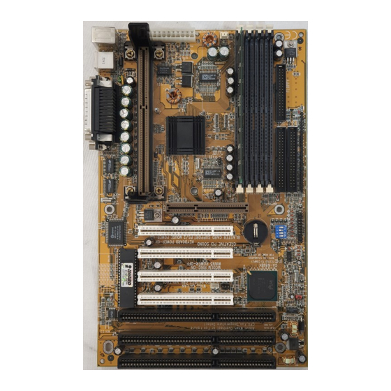
Page 33: Quick Reference For Jumpers & Connectors
COM A COM B SLOT5 SLOT3 PS/2 SLOT1 BIOS PCI 4 PCI 3 PCI 2 PCI 1 Intel POWER 440BX BANK 0 DIMM 1 BANK 1 DIMM 2 BANK 2 DIMM 3 PIIX4 BANK 3 DIMM 4 IDE 2 FLOPPY SLOT6 SLOT4 SLOT2... - Page 34 Hardware Installation Short Enter Green Mode HD : Hard Disk active LED (HD-LED) LED ANODE (+) LED CATHODE (-) FAN PWR : CPU cooling FAN Power Connector Pin No. Function GND. +12V SENSE J15 : System After Ac Back Open Soft Off Short Full On...
- Page 35 Output Soft PWR : Soft Power Switch Open Normal Operation Short Power On/Off JP7 : Wake on LAN Connector Pin No. Function +5VSB CTRL-Signal JP8 : For PCI Sound Card Connector Pin No. Function Signal Signal Signal IR: INFRARED Connector Pin No.
- Page 36 Hardware Installation JP9 : 2*11 PIN Jumper LED HD RKPS PWR: Soft Power Connector Open: Normal Operation Short: Power On/Off RES: Reset Switch Open: Normal Operation Short: For Hardware Reset System LED: Power LED PIN 1 : anode (+) PIN 2 : cathode (-) PIN 3 : cathode (-) RKPS: Speaker Connector PIN 1 : VCC...
-
Page 37: Dram Installation
3.4. DRAM INSTALLATION The main board can be installed with 8 / 16 / 32 / 64 / 128 / 256 MB 168 pins DIMM module DRAM, and the DRAM speed must be 67~100 MHz for SDRAM when system bus speed is set to 66MHz. When system bus speed is set to 100MHz, 100MHz SDRAM is required. -
Page 38: Cmos Rtc & Isa Cfg Cmos Sram
Hardware Installation DIP SWITCH (SW) FREQ. EXT.CLK. INT.CLK. CPU Type RATIO Pentium II 233 MHz Pentium II 266 MHz Pentium II 300 MHz Pentium II 333 MHz Pentium II 366 MHz Pentium II 300 MHz Pentium ... -
Page 39: Speaker Connector Installation
3.7. SPEAKER CONNECTOR INSTALLATION There is a speaker in AT system for sound purpose. The 4 - Pins connector SPK is used to connect speaker. 3.8. HARDWARE RESET SWITCH CONNECTOR INSTALLATION The RESET switch on panel provides users with HARDWARE RESET function. The system will do a cold start after the RESET switch is pushed and released by user. -
Page 41: Bios Configuration
BIOS Configuration BIOS CONFIGURATION Award's BIOS ROM has a built-in Setup program that allows users to modify the basic system configuration. This type of information is stored in battery-backed CMOS SRAM so that it retains the Setup information when the power is turned off. -
Page 42: Getting Help
4.3. GETTING HELP 4.3.1. Main Menu The on-line description of the highlighted setup function is displayed at the bottom of the screen. 4.3.2. Status Page Setup Menu / Option Page Setup Menu Press F1 to pop up a small help window that describes the appropriate keys to use and the possible selections for the highlighted item. - Page 43 BIOS Configuration • Standard CMOS setup This setup page includes all the items in standard compatible BIOS. • BIOS features setup This setup page includes all the items of Award special enhanced features. • Chipset features setup This setup page includes all the items of chipset special features. •...
-
Page 44: Standard Cmos Setup Menu
4.5. STANDARD CMOS SETUP MENU The items in Standard CMOS Setup Menu (Figure 4.2) are divided into 9 categories. Each category includes no, one or more than one setup items. Use the arrows to highlight the item and then use the <PgUp> or <PgDn> keys to select the value you want in each item. - Page 45 BIOS Configuration The times format in <hour> <minute> <second>. The time is calculated base on the 24-hour military-time clock. For example, 1 p.m. is 13:00:00. • Primary HDDs / Secondary HDDs The category identifies the types of hard disk from drive C to F that has been installed in the computer.
- Page 46 Disabled Normal Floppy Drive. Drive A Drive A is 3 mode Floppy Drive. Drive B Drive B is 3 mode Floppy Drive. Both Drive A & B are 3 mode Floppy Drives. • Video The category detects the type of adapter used for the primary system monitor that must match your video display card and monitor.
- Page 47 BIOS Configuration The category is display-only which is determined by POST (Power On Self Test) of the BIOS. Base Memory The POST of the BIOS will determine the amount of base (or conventional) memory installed in the system. The value of the base memory is typically 512 K for systems with 512 K memory installed on the motherboard, or 640 K for systems with 640 K or more memory installed on the motherboard.
-
Page 48: Bios Features Setup
4.6. BIOS FEATURES SETUP ROM PCI / ISA BIOS BIOS FEATURES SETUP AWARD SOFTWARE, INC. : Disabled Video BIOS Shadow : Enabled Virus Warning : Enabled CPU Internal Cache : Enabled External Cache : Disabled CPU L2 Cache ECC Checking : Enabled Quick Power On Self Test : Enabled... - Page 49 BIOS Configuration • CPU Internal Cache / External Cache These two categories speed up memory access. However, it depends on CPU / chipset design. The default value is Enabled. Enabled Enable cache Disabled Disable cache • CPU L2 Cache ECC Checking The default value is Disabled.
- Page 50 • Boot Sequence This category determines which drive computer searches first for the disk operating system (i.e., DOS). Default value is A, C, SCSI. X1, X2, X3 System will first search for X1 disk drive then X2 disk drive and then X3 disk drive. •...
- Page 51 BIOS Configuration • Typematic Rate (Chars / Sec) The default value is 6. 6-30 Set the maximum Typematic rate from 6 chars. Per second to 30 chars. Per second. • Typematic Delay (Msec) The default value is 250. 250-1000 Set the time delay from first key to repeat the same key in to computer.
-
Page 52: Chipset Features Setup
• OS Select For DRAM>64MB The default value is Non-OS2. Non-OS2 Using non-OS2 operating system. Using OS2 operating system and DRAM>64MB. • Video BIOS Shadow It determines whether video BIOS is able to copy to RAM, however, it is optional from chipset design. Video Shadow will increase the video speed. The default value is Enabled. - Page 53 BIOS Configuration • EDO CASx# MA Wait State The default value is 1 Set EDO CASx# MA Wait State to 1. Set EDO CASx# MA Wait State to 2. • EDO RASx# Wait State The default value is 1 Set EDO RASx# Wait State to 1. Set EDO RASx# Wait State to 2.
- Page 54 • Video RAM Cacheable The default value is Disabled. Disabled Disable this function. Enabled Enable this function to get better VGA performance; while some brands of VGA must be disabled this function (e.g.ET4000W32P). • 16 Bit I/O Recovery Time The default value is 1. Set 16 Bit I/O recovery time from 1 to 4.
- Page 55 BIOS Configuration • Slow Down CPU Duty Cycle The default value is Normal. Normal Disable Slow Down CPU Duty Cycle. 12.5% Set Slow Down CPU Duty Cycle to 12.5%. 25.0% Set Slow Down CPU Duty Cycle to 25.5%. 37.5% Set Slow Down CPU Duty Cycle to 37.5%. 50.0% Set Slow Down CPU Duty Cycle to 50.0%.
- Page 56 Disabled Disable this function. Enabled System will check the CPUFAN status. • CPUFan Fail Alarm The default value is Disabled. Disabled Disable this function. Enabled Alarm When CPUFAN Failed. • Current CPU Temperature Detect CPU Temperature automatically. • Current CPUFAN Speed Detect CPU Fan speed status automatically.
-
Page 57: Power Management Setup
BIOS Configuration 4.8. POWER MANAGEMENT SETUP ROM PCI / ISA BIOS POWER MANAGEMENT SETUP AWARD SOFTWARE, INC. Reload Global Timer Events Power Management : Enable IRQ [3-7,9-15] ,NMI : Enabled PM Control by APM : Yes Primary IDE 0 : Disabled : Disable Suspend Mode Primary IDE 1... - Page 58 Disable software APM function. • Suspend Mode The default value is Disable. Disabled Disable Suspend Mode. 1 min - 1 Hour Setup the timer to enter Suspend Mode. • HDD Power Down The default value is Disable. Disable Disable HDD Power Down mode function. 1-15 mins.
- Page 59 BIOS Configuration The default value is Enabled. Disabled Disable this function. Enabled Stop CPU FAN when entering Suspend mode. • Resume by Alarm The default value is Disabled. Disabled Disable this function. Enabled Enable alarm function to POWER ON system. If the “Resume by Alarm”...
- Page 60 The default value is Enabled. Disabled Disable this function. Enabled Enable monitor Floppy Disk for Green event. • Serial Port The default value is Enabled. Disabled Disable this function. Enabled Enable monitor Serial Port for Green event. • Parallel Port The default value is Disabled.
-
Page 61: Pnp/Pci Configuration
BIOS Configuration 4.9. PNP/PCI CONFIGURATION ROM PCI / ISA BIOS PNP/PCI CONFGURATION AWARD SOFTWARE, INC. PNP OS Installed : No Used MEM base addr : N/A Resources Controlled by : Manual *Used MEM Length : 8K Reset Configuration Data : Disabled : Enabled Assign IRQ For USB IRQ-3 assigned to... - Page 62 • Reset Configuration Data The default value is Disabled. Disabled Disable this function. Enabled Enable clear PnP information in ESCD. • IRQ (3,4,5,7,9,10,11,12,14,15), DMA(0,1,3,5,6,7) assigned to The default value is "Legacy ISA" or "PCI/ISA PnP". Legacy ISA The resource is used by Legacy ISA device. PCI/ISA PnP The resource is used by PCI/ISA PnP device (PCI or ISA).
-
Page 63: Load Bios Defaults
BIOS Configuration 4.10. LOAD BIOS DEFAULTS ROM PCI / ISA BIOS LOAD SETUP DEFAULTS AWARD SOFTWARE, INC. STANDARD CMOS SETUP INTEGRATED PERIPHERALS BIOS FEATURES SETUP USER PASSWORD CHIPSET FEATURES SETUP IDE HDD AUTO DETECTION POWER MANAGEMENT SETUP SAVE & EXIT SETUP PNP/PCI CONFIGURATION Load BIOS Defaults (Y/N)? N EXIT WITHOUT SAVING... -
Page 64: Load Performance Defaults
4.11. LOAD PERFORMANCE DEFAULTS ROM PCI / ISA BIOS LOAD SETUP DEFAULTS AWARD SOFTWARE, INC. STANDARD CMOS SETUP INTEGRATED PERIPHERALS BIOS FEATURES SETUP USER PASSWORD CHIPSET FEATURES SETUP IDE HDD AUTO DETECTION POWER MANAGEMENT SETUP SAVE & EXIT SETUP PNP/PCI CONFIGURATION EXIT WITHOUT SAVING LOAD BIOS DEFAULTS Load PERFORMANCE Defaults (Y/N)? N... -
Page 65: Integrated Peripherals
BIOS Configuration 4.12. INTEGRATED PERIPHERALS ROM PCI / ISA BIOS INTEGRATED PERIPHERALS AWARD SOFTWARE, INC. IDE HDD Block Mode : Enabled PS/2 Mouse Power On : Disabled IDE Primary Master PIO : Auto Keyboard Power On : Disabled IDE Primary Slave PIO : Auto * KB Power On Multikey : Enter... - Page 66 • IDE Primary Slave PIO (for onboard IDE 1st channel). The default value is Auto. Auto BIOS will automatically detect the IDE HDD Accessing mode. Mode0~4 Manually set the IDE Accessing mode. • IDE Secondary Master PIO (for onboard IDE 2nd channel). The default value is Auto.
- Page 67 BIOS Configuration • IDE Secondary Master UDMA. The default value is Auto. Auto BIOS will automatically detect the IDE HDD Accessing mode. Disabled Disable UDMA function. • IDE Secondary Slave UDMA. The default value is Auto. Auto BIOS will automatically detect the IDE HDD Accessing mode.
- Page 68 • Onboard Serial Port 1 The default value is 3F8/IRQ4. Auto BIOS will automatically setup the port 1 address. 3F8/IRQ4 Enable onboard Serial port 1 and address is 3F8. 2F8/IRQ3 Enable onboard Serial port 1 and address is 2F8. 3E8/IRQ4 Enable onboard Serial port 1 and address is 3E8.
-
Page 69: User Password
BIOS Configuration • PS/2 Mouse Power on The default value is Disabled. Disabled Disable PS/2 Mouse Power on . Left Double Click twice on PS/2 mouse left button to Power on system. Right Double Click twice on PS/2 mouse right button to Power on system. •... -
Page 70: Ide Hdd Auto Detection
When you select this function, the following message will appear at the center of the screen to assist you in creating a password. ROM PCI / ISA BIOS USER PASSWORD AWARD SOFTWARE, INC. STANDARD CMOS SETUP INTEGRATED PERIPHERALS BIOS FEATURES SETUP USER PASSWORD CHIPSET FEATURES SETUP IDE HDD AUTO DETECTION... - Page 71 BIOS Configuration R O M PC I / IS A B IO S ID E H D D D A U T O D E T E C T IO N AWA R D S O F T WA R E , IN C . H A R D D IS K S T Y P E S IZ E...
-
Page 72: Save & Exit Setup
4.15. SAVE & EXIT SETUP ROM PCI / ISA BIOS SAVE & EXIT SETUP AWARD SOFTWARE, INC. STANDARD CMOS SETUP INTEGRATED PERIPHERALS BIOS FEATURES SETUP USER PASSWORD CHIPSET FEATURES SETUP IDE HDD AUTO DETECTION POWER MANAGEMENT SETUP SAVE & EXIT SETUP PNP/PCI CONFIGURATION SAVE to CMOS and EXIT (Y/N)? N EXIT WITHOUT SAVING... -
Page 73: Exit Without Saving
BIOS Configuration 4.16. EXIT WITHOUT SAVING ROM PCI / ISA BIOS EXIT WITHOUT SAVING AWARD SOFTWARE, INC. STANDARD CMOS SETUP INTEGRATED PERIPHERALS USER PASSWORD BIOS FEATURES SETUP IDE HDD AUTO DETECTION CHIPSET FEATURES SETUP SAVE & EXIT SETUP POWER MANAGEMENT SETUP EXIT WITHOUT SAVING PCI CONFIGURATION Quit Without Saving (Y/N)? N... - Page 75 Product Name: Mother Board residential installations. This equipment GA-6BX Model Number: generates, uses, and can radiate radio Conforms to the following specifications: FCC Part 15, Subpart B, Section 15.107(a) and Section 15.109(a), frequency energy, and if not installed and used...
- Page 76 Ausschlager Weg 41, 1F, 20537 Hamburg, Germany declare that the product ( description of the apparatus, system, installation to which it refers) Mother Board GA-6BX is in conformity with (reference to the specification under which conformity is declared) in accordance with 89/336 EEC-EMC Directive...