
Related Manuals for Audio Technica 5000 Series


Summary of Contents for Audio Technica 5000 Series
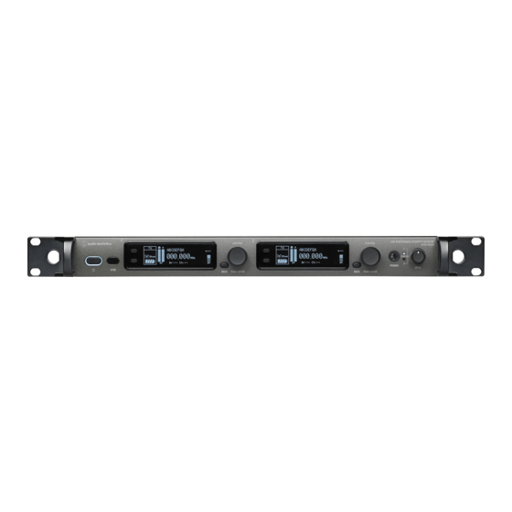
- Page 1 5000 Series User Manual UHF Wireless Systems ATW-R5220 Dual Receiver ATW-R5220DAN Dual Receiver with Dante Output ATW-T5201 Body-Pack Transmitter ATW-T5202 Handheld Transmitter (without capsule)
-
Page 2: Table Of Contents
Contents Introduction .................2 Making connections (basic connections) ........27 Important information ..............2 Making connections (cascade connections) ......28 Notes on use ................4 Achieving stable reception ............29 Maintenance ................4 Rack-mounting the receiver............29 Part names and functions ............5 Troubleshooting .................30 ATW-R5220/ATW-R5220DAN ................5 ATW-R5220/ATW-R5220DAN ................ 30 ATW-T5201 ...................... -
Page 3: Introduction
Introduction Thank you for purchasing this Audio-Technica product. Before using the product, read through this user manual to ensure that you will use the product correctly. Please keep this manual for future reference. The frequency band can be checked by the model number of the product. You can confirm the model number of your product by the rating label. Example: ATW-R5220DG1 Band name Model number... - Page 4 Important information For customers in the USA/Canada CAUTION RISK OF ELECTRIC SHOCK DO NOT OPEN Caution: To prevent electric shock, do not remove the cover. There are no user-serviceable parts inside. Internal adjustments are for qualified professionals only. Refer all servicing to qualified service personnel. The lightning flash with arrowhead symbol, within an equilateral triangle, is intended to alert the user to the presence of uninsulated “dangerous voltage”...
-
Page 5: Notes On Use
Notes on use • Be sure to read the user manual for any microphone or cable that you attach to the product. • Disconnect the power cable from the outlet when this product is not in use. • Turn off the power of this product before connecting or disconnecting cables. •... -
Page 6: Part Names And Functions
Part names and functions ATW-R5220/ATW-R5220DAN Front panel ❶ ❷ ❸ ❹ ❺ ❻ ❼ ❸ ❹ ❺ ❻ ❼ ❽ ❾ ❿ ❶ Power button ( Use to turn the receiver on or place in standby. : Symbol indicates standby.) ❷... - Page 7 Part names and functions Rear panel The figure below is ATW-R5220. ❶ ❷ ❸❹ ❸ ❹ ❷ ❶ ❺ ❻ ❼ ❶ Antenna input jack : Symbol indicates direct current.) Each jack supplies DC12 V to a connected antenna. Additionally, other compatible antenna accessories (sold separately) can be connected. ❷...
-
Page 8: Atw-T5201
Part names and functions ATW-T5201 ❶ ❷ ❹ ❷ ❸ ❺ ❽ ❻ ❾ ⓫ ❼ ❿ ❶ ❼ Indicator Lever push switch LED that shows the status of the transmitter. Use to select various settings. When the power is turned ON: Solid green UP ( ) When the transmitter is muted: Solid red Turn to the right to change a selection. -
Page 9: Atw-T5202
Part names and functions ATW-T5202 ❶ ❷ ❸ ❹ ❺ ❻ ❼ ❽ ❾ ❿ ⓫ ⓬ ⓭ ❶ ❾ Interchangeable microphone capsule (sold separately) SYNC button ❷ Use to IR SYNC with the receiver (ATW-R5220/ATW-R5220DAN). Display ❿ Power switch Shows the current status. -
Page 10: How To Insert Batteries
How to insert batteries ATW-T5201 ATW-T5202 Slide the battery cover latches inward as shown by the arrows. Rotate the grip case of the battery compartment. Open the battery cover. • Put your finger on the hook of the battery cover and pull it to open the battery cover. -
Page 11: How To Attach And Detach The Interchangeable Microphone Capsule (Only For Atw-T5202)
How to attach and detach the interchangeable microphone capsule (only for ATW-T5202) How to attach Attach the microphone capsule to the body of the transmitter. Rotate the microphone capsule clockwise to tighten it. How to remove Rotate the microphone capsule counterclockwise to loosen it. Detach the microphone capsule from the body of the transmitter. -
Page 12: How To Read The Display
How to read the display ATW-R5220/ATW-R5220DAN Main screen ❶ ❷ ❸ ❹ ❺ ❻ VOCAL1 000.000 G r 06 C h 1 2 ❼ ❽ ❾ ❿ ⓫ ❶ ❼ Transmitter information display area Group indicator Information on the connected transmitter is displayed. Refer to ❽... - Page 13 How to read the display Level meter screen ❶ ❷ -74 dBm TX - RF PWR -40 -30 -24 -18 -15 -12 -10 -8 -6 -4 -2 0 +2 +4 +6 dBu ❸ ❹ ❺ ❻ ❶ ❹ RF transmission output indicator (transmitter) Audio output indicator (receiver) ❷...
-
Page 14: Atw-T5201/Atw-T5202
How to read the display ATW-T5201/ATW-T5202 The main screen is displayed when the power is switched on. If you press the UP/Down button on the main screen, the screen display is switched. ❶ ❻ ❼ ❽ 000.000 VOCAL1 02 Ch ❷... -
Page 15: How To Operate
How to operate Basic operation Using IR SYNC Turn on the main power button of the receiver This function allows you to make settings on the receiver that are (ATW-R5220/ATW-R5220DAN). specified for the transmitter. When IR SYNC is started as part of setting the receiver, the “Communication in standby”... -
Page 16: Settings
Settings Various settings can be made from the menu screen shown on the ATW-T5201/ATW-T5202 display. The transmitter's (ATW-T5201/ATW-T5202) UP/DOWN button operation is explained below. While this explanation uses the UP/DOWN button ATW-R5220/ATW-R5220DAN operation of ATW-T5202 as its example, it can easily be applied to either transmitter. -
Page 17: Setting Atw-R5220/Atw-R5220Dan
Setting ATW-R5220/ATW-R5220DAN List of setting items Setting the operating frequency FREQUENCY MANUAL Set the operating frequency. Manual setting Gr/Ch From the menu screen, turn the control dial, select NAME Set the channel name. [FREQUENCY] and then press the control dial. AUDIO Set the audio output level. -
Page 18: Setting The Audio Output Level
Setting ATW-R5220/ATW-R5220DAN Selecting the group you want to scan: Setting the audio output level Confirm the scan result by selecting [OK] and then pressing the control dial. From the menu screen, turn the control dial, select [AUDIO] and • If you want to scan over again, select [Retry]. then press the control dial. -
Page 19: Setting The Squelch Level
Setting ATW-R5220/ATW-R5220DAN Setting the squelch level Setting the system-related functions Setting automatically Setting the lock From the menu screen, turn the control dial, select [SQUELCH] Set this function to prevent the receiver settings from being changed. and then press the control dial. •... - Page 20 Setting ATW-R5220/ATW-R5220DAN Setting group/channel editing Setting the backup frequency mode Setting group/channel If you set the backup frequency in advance, you can switch the frequency of the transmitter and receiver with the transmitter. It is Groups/Channels 01 to 10 can be edited. convenient to set this function when you want to switch the frequency •...
- Page 21 Setting ATW-R5220/ATW-R5220DAN Setting the AF level meter on the main screen Resetting Switch the AF level meter on the main screen between [Receiver (RX)] This returns the receiver settings to their factory defaults. and [Transmitter (TX)]. From the menu screen, turn the control dial, select [UTILITIES] •...
-
Page 22: Setting Network
Setting ATW-R5220/ATW-R5220DAN Setting network Setting the log message Set whether to send the log message to the Syslog server. By connecting the receiver and PC, you can use the dedicated app for From the menu screen, turn the control dial, select [NETWORK] monitoring or controlling with the PC. -
Page 23: Using Test Tool
Setting ATW-R5220/ATW-R5220DAN Setting MAC address Setting the DANTE's IP From the menu screen, turn the control dial, select [NETWORK] From the menu screen, turn the control dial, select [DANTE] and and then press the control dial. then press the control dial. Turn the control dial, select [MAC ADDRESS]. -
Page 24: Setting Atw-T5201/Atw-T5202
Setting ATW-T5201/ATW-T5202 List of setting items Setting by group/channel From the menu screen, press the UP/DOWN button to select FREQUENCY MANUAL Set the transmission frequency. [FREQUENCY], and then press the SET button. Gr/Ch FREQUENCY NAME Set the channel name. GAIN Set the microphone input gain. -
Page 25: Setting The Microphone Input Gain
Setting ATW-T5201/ATW-T5202 Setting the microphone input gain Setting HPF (High-Pass Filter) From the menu screen, press the UP/DOWN button to select From the menu screen, press the UP/DOWN button to select [GAIN], and then press the SET button. [HPF], and then press the SET button. GAIN Press the UP/DOWN button to select the gain you wish to set. -
Page 26: Setting The Function
Setting ATW-T5201/ATW-T5202 Setting the function Setting the system-related functions Setting the function for the function button Setting the battery type Select the function to be performed when the function button is Set the type of batteries used. pressed and held •... - Page 27 Setting ATW-T5201/ATW-T5202 Setting the indicator Resetting The indicator LED can be turned [On] or [Off]. This returns the transmitter settings to their factory defaults. • The default setting is [On]. From the menu screen, press the UP/DOWN button to select [UTILITIES], and then press the SET button.
-
Page 28: How To Attach The Transmitter (Atw-T5201)
How to attach the transmitter (ATW-T5201) The ATW-T5201 transmitter is equipped with a clip that can be used to attach the transmitter to a belt, etc. You can reverse the direction of the input connector by Pull both sides of the clip firmly to the outside to remove attaching the clip in the opposite direction. -
Page 29: Making Connections (Cascade Connections)
Making connections (cascade connections) Using the antenna output jack makes it possible to connect an additional 7 receivers (for a total of 8) in a cascade connection without using an antenna divider. • When cascading receivers, connect either the included whip antennas or external antennas to the main receiver's antenna input jacks, and then, cascade each receiver via BNC cable. -
Page 30: Achieving Stable Reception
Achieving stable reception Low RF signal may result if there are obstructions between receiver antennas and transmitter(s). In such a case, reposition the antennas to get better reception. Use external antennas (sold separately) if the installation space is limited. Rack-mounting the receiver •... -
Page 31: Troubleshooting
Troubleshooting ATW-R5220/ATW-R5220DAN Symptoms Causes and countermeasures Reference page The power can't be turned on. Confirm that the power cable is correctly connected. There is no voice output. The voice output level is low. Confirm that the transmitter/receiver channels are correct p. -
Page 32: Dimensions
Dimensions ATW-R5220/ATW-R5220DAN 400.0 482.0 (Unit: mm) -
Page 33: Atw-T5201
Dimensions ATW-T5201 (Unit: mm) ATW-T5202 (Unit: mm) -
Page 34: Specifications
Specifications Overall system specifications Operating frequencies Frequency range Number of frequencies ATW-R5220/ATW-R5220DAN Band DG1: 470.125 to 699.875 MHz 9,191 Band DF1: 470.125 to 607.875 MHz, 657.100 to 662.900 MHz 5,511+233 ATW-T5201/ATW-T5202 Band DE1: 470.125 to 590.000 MHz 4,796 Band EG1: 580.000 to 699.875 MHz 4,796 Band FE2:... -
Page 35: Atw-T5201
Specifications ATW-T5201 RF output power High: 50 mW, Mid: 10 mW, Low: 2 mW (switchable), at 50 ohms Spurious emissions Following federal and national regulations Input connection Four pin locking connector Pin 1: GND Pin 2: INST INPUT Pin 3: MIC INPUT Pin 4: DC BIAS +10 V High-pass (low-freq. - Page 36 Audio-Technica Corporation 2-46-1 Nishi-naruse, Machida, Tokyo 194-8666, Japan www.audio-technica.com ©2018 Audio-Technica Corporation Global Support Contact: www.at-globalsupport.com 232417000-02-01 ver.1 2018.09.15...