
Related Manuals for Fujitsu FP-510II


Summary of Contents for Fujitsu FP-510II
- Page 1 KA02072-Y904-05 THERMAL PRINTER Type name:FP-510II/FP-510 USER’S MANUAL Fujitsu Isotec Limited...
- Page 2 Notes on use All the company names and product names mentioned in this document are the trademarks or registered trademarks of their respective companies. This document is subject to change without notice. Unauthorized reproduction or copying of this document, whether in part or in whole is prohibited.
- Page 3 How to Use This Product Safely Using This Document This document contains important information for using the product safely. Carefully read and understand this manual before using the product. After reading this manual, store it with care at a place where it can be found at any time, such as near the product.
- Page 4 The contents of this manual may be revised without prior notice. No part of this manual may be reproduced in any form without permission. ■About the name of this printer. ・Model name : FP-510 ・Type name : FP-510II / FP-510 Copyright © 2008-2016 FUJITSU ISOTEC LIMITED. 3 / 125...
- Page 5 Declaration of Conformity FCC Compliance Statement This device complies with part 15 of the FCC Rules. Operation is subject to the following two conditions: (1) This device may not cause harmful interference, and (2) this device must accept any interference received, including interference that may cause undesired operation.
- Page 6 Canadian Compliance Statement This device complies with Industry Canada’s licence-exempt RSSs. Operation is subject to the following two conditions: (1) This device may not cause interference; and (2) This device must accept any interference, including interference that may cause undesired operation of the device.
- Page 7 Safety Precautions Warning Marks This document uses the following warning marks in order to ensure safe and correct use of the product and to prevent any harm or damage to you or to others. Warning Caution Used for instructions intended Used for instructions intended to to alert the user to the risk of alert the user to the risk of injury...
- Page 8 Warning Only the AC adapter specified by Fujitsu Isotec may be used with this printer. Using any other AC adapter carries the risk of fire and electric shock. When connecting the drawer kick cable, do not use any method not specified in the instruction manual. This may result in fire or electric shock.
- Page 9 In case of emergency involving heat, smoke or acrid fumes occurring, immediately turn off the power switch, and remove the power plug from the outlet. Request the sales company (or maintenance service center) for repair after confirming the smoke has gone. Users must under no circumstances whatsoever try to repair the product due to the dangers involved.
- Page 10 Caution Do not place heavy objects on the product. This may destroy the balance and cause the product to fall over or down, resulting in injuries. Do not locate the product on a place with severe vibration, or on an unstable or inclined surface. The product may fall over or down, resulting in injuries.
- Page 11 When shifting the product, be sure to remove the power plug from the outlet. In addition, also remove the connection cable, etc. Pay adequate attention to your feet while performing the operation. Scratching the power cable may result in electric shock or fire, and injuries may also be caused if the product falls over or down.
- Page 12 The device with a Bluetooth specification in this product includes a Bluetooth communication function. You may not be able to use this product as a result of the radio laws in various countries. The radio laws are determined separately by each country and their content will differ depending on that country.
- Page 13 Notes on use related to the Bluetooth specification The frequency band used by this product is operated by intra-facility radio stations (radio stations requiring a license) for mobile unit identification in industries such as microwave ovens, science and medical devices, and specified low power radio stations and amateur radio stations (radio stations requiring a license).
-
Page 14: Table Of Contents
TABLE OF CONTENTS 1. Appearance and Names of Components ···························································15 1-1. Names of Components ·········································································15 1-2. The explanation of Symbols on the printer ··············································16 1-3. Package Contents ················································································18 2. AC Adapter and Thermal Roll Paper ······························································19 2-1. AC adapter ·························································································19 2-2. - Page 15 B-3.Powered USB Interface ········································································73 B-4.USB Interface ·····················································································74 B-5.Dual Interface ·····················································································75 B-6.LAN Interface ·····················································································76 B-7.Bluetooth Interface ··············································································78 B-8.Drawer Kick Connector ········································································81 B-9.Specifications of Power Supply ······························································83 Appendix C: Special Modes ···············································································84 C-1.Test Printing ······················································································84 C-2.Hex Dump ··························································································85 C-3.Setting Up the Printer ·········································································86 C-4.Setup Items ························································································116 C-5.Sample Print ······················································································122 14 / 125...
-
Page 16: Appearance And Names Of Components
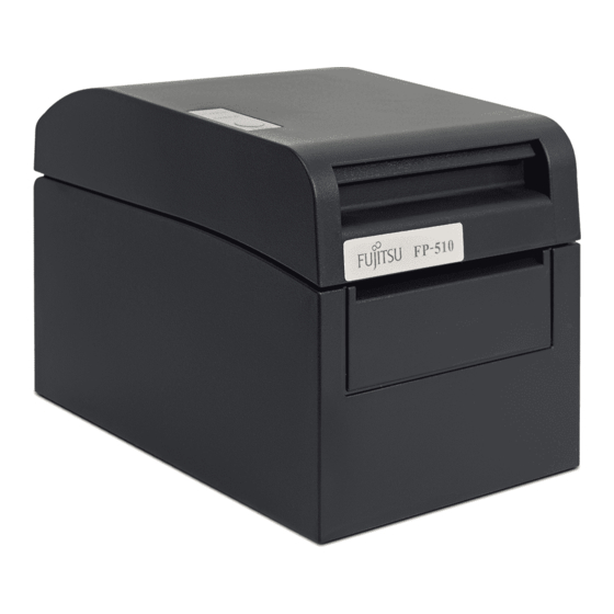
1. Appearance and Names of Components 1. Appearance and Names of Components 1-1. Names of Components Control panel This panel contains status lamps and operating switches. Top cover Open and close this cover to replace forms. Power switch Release lever This switch turns the printer power on and off. -
Page 17: The Explanation Of Symbols On The Printer
1-2. The explanation of Symbols on the printer • Power Switch Turns the printer power ON (Printable Condition)/ stand-by (Power Stand-by Condition). Stand-by • Drawer This product uses a special-purpose modular connector for the cash drawer. Do not attempt to use other types of connectors such as public telephone connectors. 16 / 125... - Page 18 ・Direct Current This symbol indicates "Direct Current". ・Alternating Current This symbol indicates "Alternating Current". 17 / 125...
-
Page 19: Package Contents
1-3. Package Contents Thermal paper MANUAL PRINTER DRIVER UTILITY SOFT Quick start guide 18 / 125... -
Page 20: Ac Adapter And Thermal Roll Paper
2. AC Adapter and Thermal Roll Paper 2. AC Adapter and Thermal Roll Paper 2-1. AC adapter Only use the AC adapter specified below. Manufacture: Asian Power Devices Inc. Model No.: DA-36B24 Order No.: KA02951-0120 Input: 100 to 240V , 50-60Hz, 1.1A Output: , 1.5A Warning: Only use authorized AC adapters. -
Page 21: Recommended Thermal Paper
2-3. Recommended Thermal Paper Manufacturer Product Quality characteristics Paper Density name thickness specification Oji Paper Co., PD160R Monochrome thermal 75µm 100% Ltd. paper (high-grade preservation type) PD190R Monochrome thermal 75µm 100% paper (mid-grade preservation type) Nippon Paper HD75 Monochrome thermal 150µm 130% Industries Co.,... - Page 22 Caution: Red or blue printing on two-color thermal paper has an inferior preservation characteristic that is equivalent to that of normal thermal paper. Caution: Printouts on label paper or thick paper may contain blurs or voids, depending on the humidity and other environmental conditions. Adjust the print speed and print density as appropriate for the type of paper used.
-
Page 23: Preparations
3. Preparations 3. Preparations No printer cable is provided with the product. Obtain a printer cable suitable for the product interface. If you have any questions, consult your dealer. Before connecting or disconnecting cables, make sure of the following: 1)The power to the printer and all other devices connected to the printer is turned off. - Page 24 For a unit with serial and parallel interfaces Connector cover Insert Serial interface cable * Secure the connector with screws after making the connection. Parallel interface cable * Secure the connector with Insert clasps after making the connection. Direct Current (This symbol indicates "Direct Current".) Interface connector Interface connector...
- Page 25 For a unit with USB interface Connector Cover USB Interface Cable Insert Type-A * Another USB device can be connected through this connector to a PC using the printer as a USB hub. USB Interface Cable Type-B * Connect the printer to a PC through this connector.
- Page 26 For a unit with Powered USB interface Connector cover Insert Powered USB interface cable Insert Interface connector (Powered USB interface) Drawer kick connector 25 / 125...
- Page 27 For a unit with Dual interface Connector cover Insert Serial interface cable * Secure the connector with screws after making the connection. USB Interface Cable Type-B * Connect the printer to a PC through this connector. Insert Interface Connector (USB Interface Type-B) Interface connector * Connect the printer to a PC (Serial interface)
- Page 28 For a unit with LAN interface Connector cover Insert LAN interface cable Insert Interface connector (LAN interface) Power connector Drawer kick connector 27 / 125...
- Page 29 For a unit with Bluetooth and USB interface USB Interface Type-B Connector DIP Switch Power Connector Drawer Kick Connector Bluetooth Antenna Caution: Do not touch DIP switch during normal usage. Otherwise, it may not be able to print correctly. 28 / 125...
-
Page 30: Connecting The Drawer Kick Cable
3-2. Connecting the drawer kick cable Open the connector cover at the rear of the printer by pulling it up, and connect the drawer kick cable to its rear connector socket. Close the cover after connecting the cable. Caution: If the cable is arranged so that it extends from the rear, remove the inserts in the connector cover with nippers or a similar tool. -
Page 31: Connecting The Ac Adapter
3-3. Connecting the AC Adapter (1) Connect the AC adapter to the AC adapter power cable. Warning: Only use authorized AC adapters. Warning: Do not use any other bundled AC adapter other than designed for this printer. Caution: Before connecting the AC adapter, turn off the power switches on the printer and all the devices connected to the printer. - Page 32 Caution: As the connector is clipped in place after insertion in order to prevent it from falling off, when performing insertion, (1) grip the cable base with one hand, (2) slide the outer part of the connector upwards with the other hand (3) and push in until it locks into place.
-
Page 33: Disconnecting The Ac Adapter
3-4. Disconnecting the AC Adapter To unplug the AC adapter cable, grasp the connector as shown in the picture below and pull it out. The lock mechanism of the connector will then disengage, and the cable can be unplugged easily. Conversely, forcibly pulling on the cable itself may damage the connector. -
Page 34: Turning On The Power
3-5. Turning on the Power After the AC adapter is connected, turn on the power switch at the side of the printer. The POWER lamp on the control panel lights. Control panel Power switch 3-6. Installing the Printer Software Referring to the "Installation Guide" (Install_Guide_E.pdf) contained on the CD-ROM provided with the printer, install the printer driver and utility software. -
Page 35: Inserting Paper For Printing
4. Inserting Paper for Printing 4. Inserting Paper for Printing 4-1. Replacing paper (1)Grasp the top cover, pull up the cover release lever, and open the top cover. Top part of the top cover ▼ ▲ Bottom part of the cover release lever (2) When manipulating the top cover, note that the cover seems to lock in position before it is open completely. - Page 36 Caution: Do not touch the thermal head. Doing so may result in damage from static electricity. Release lever Top Cover Thermal head Roll holder Separator 35 / 125...
- Page 37 (3) Adjust the separator to the width of the roll paper. For roll paper with a width of 80 mm, the separator need not be removed. For roll paper with a width of 70, 60, or 58 mm, remove the separator and attach it again at the correct width.
- Page 38 (4) Set the separator to a position appropriate for the width of the roll paper, as shown below. 60mm 58mm 70mm 80mm Separator setting in detail Caution: Adjust the separator to the width of the roll paper. To use roll paper with a width of 83 mm, remove the separator.
- Page 39 58 mm setting groove 60 mm setting groove Roll paper width of 58 mm Roll paper width of 60 mm 80 mm setting groove 70 mm setting groove Roll paper width of 70 mm Roll paper width of 80 mm 38 / 125...
- Page 40 How to attach the separator Attach the separator at the rear hook for the axis. Rear hook for the axis Aligned horizontally Caution: Push the separator down until it engages with an audible click, and confirm that the top of the separator is aligned horizontally.
- Page 41 (3) When using a new paper roll, remove the glued portion of the paper as well as the part to which adhesive tape is affixed. Caution: Since the glued portion of the paper should not be printed on, remove about one turn (about 40 cm) of the roll paper from the beginning so that none of the remaining paper has glue on it.
- Page 42 Paper not protruding Roll paper inserted from the front cover upside down Caution: Before loading a new roll, make sure that an old core does not remain in the roll holder. Leaving an old core will cause a paper-near-end error condition. Caution: The roll paper must have no deformities.
- Page 43 (5)Place the paper in the correct orientation, and carefully close the top cover. Caution: Place the paper in the correct orientation. If the top cover is closed while the paper is not correctly in place, a paper jam or misaligned printing might occur. Caution: To close the top cover, press it down near its center (the location pointed at in the figure below) until you hear the lock engage.
-
Page 44: Control Panel
5. Control Panel 5. Control Panel 5-1. Control Panel POWER lamp (●) Lights when the power switch is turned on and power is supplied to the printer. ERROR lamp (●) Lights or blinks to indicate errors. FEED switch Pressing this switch once advances the paper one line. - Page 45 Unrecoverable errors Error State LED Lamp Lighting Patterns Internal error POWER(●) ――●―●― ERROR(●) ●――――― Repetition of one blink of the lamp and two blinks of the lamp Head not POWER(●) ――●―●―●― installed ERROR(●) ●――――――― Repetition of one blink of the lamp and ...
-
Page 46: Preventing And Clearing Paper Jams
6. Preventing and Clearing Paper Jams 6. Preventing and Clearing Paper Jams 6-1. Preventing Paper Jams Do not touch the paper while the paper is being ejected or cut. Holding or pulling the paper by hand during ejection might cause a paper jam, incorrect cutting, or a feed error. -
Page 47: Troubleshooting
7. Troubleshooting 7. Troubleshooting This chapter describes the appropriate action to be taken in cases where the printer is not operating correctly or fails to produce clean printouts. 7-1. Power-on Problems and Errors Symptom Cause Corrective action Although the power (1) The power cable is (1) Connect the power cable. -
Page 48: Printing-Related Problems
7-3. Printing-related Problems Symptom Causes Corrective action Printing does not (1) The interface cable is (1) Connect the interface cable begin. disconnected or broken. correctly, or replace it. (2) The printer setup is (2) Set up the printer correctly. incorrect. Example: An incorrect baud rate is set. -
Page 49: Regular Cleaning
8. Regular Cleaning 8. Regular Cleaning Printed characters may not be completely formed if paper residue, dust, or a similar material is present. To ensure proper printing, remove any paper residue and dust on the paper holder, paper transport components, platen roller, and surface of the thermal head. -
Page 50: Cleaning The Platen Roller
8-2. Cleaning the Platen Roller The cleaning procedure is as follows. (1) With paper inserted in the printer, turn off the printer power switch once, and turn on the switch again while holding down the FEED switch on the control panel. Then, the data shown below is printed. Caution: If you have passed the item that you want to select, repeatedly press the FEED switch briefly until you return to the first item. - Page 51 Then, press and hold down the FEED switch for one second or longer to accept the selection. The printer enters platen roller cleaning mode. The printer prints the following and cuts the paper when it enters platen roller cleaning mode: PLATEN ROLLER CLEANING MODE 1.
- Page 52 (5) After completing cleaning, reposition the roll paper, and close the top cover. Caution: Take care not to dent or otherwise damage the platen roller. A dent on the platen roller may result in incomplete printing or line feed errors. Caution: Each time that the FEED switch is pressed, the platen roller is rotated by 1/12 of a turn.
-
Page 53: Cleaning The Thermal Head
8-3. Cleaning the Thermal Head (1) Before attempting to clean the thermal head, be sure to turn off the printer power switch. (2) Open the top cover. (3) Using an alcohol solvent, remove black paper particles and other residue from the surface of the thermal head. If the printer printed on label paper, any adhesive matter adhering to the surface of the thermal head must be removed. -
Page 54: Cleaning The Cutter Blade And Frame
8-4. Cleaning the Cutter Blade and Frame If the printer printed on full-sheet label paper, any adhesive matter adhering to the cutter blade and frame must be removed. Even when label paper has been cut normally, clean the cutter blade at an interval of about once a month to ensure stability in cutting. - Page 55 The cleaning procedure is as follows. (1) With paper inserted in the printer, turn off the printer power switch once, and turn on the switch again while holding down the FEED switch on the control panel. Then, the data shown below is printed. Caution: If you have passed the item that you want to select, repeatedly press the FEED switch briefly until you return to the first item.
- Page 56 Then, press the FEED switch for one second or longer to accept the selection. The printer enters cutter cleaning mode. The printer prints the following and cuts the paper when it enters cutter cleaning mode: CUTTER CLEANING 1. Open Cover, and remove Roll Paper. 2.
- Page 57 - Cleaning the Upper cutter Using a general-purpose utility knife, flathead screwdriver, or similar tool, remove the adhesive matter adhering to the inner side and edge of the Upper cutter. Caution: Be very careful not to damage the edge of the Upper cutter when handling the utility knife or screwdriver.
- Page 58 - Cleaning the Lower cutter Using a general-purpose utility knife, flathead screwdriver, or similar tool, remove the adhesive matter adhering to the surface and edge of the Lower cutter. Caution: Be very careful not to damage the edge of the Lower cutter when handling the utility knife or screwdriver.
- Page 59 Using the cleaning sheet or a similar material, wipe off the adhesive matter adhering to the Lower cutter. Lower cutter Caution: Although the edge of the Lower cutter is not as sharp as the edges of utility knives generally used in offices, there is a risk of injury to a finger that is moved while pressed directly against the edge of the cutter.
-
Page 60: Notes On Use
9. Notes on Use 9. Notes on Use (1) Printing at a high rate might result in unclear printing. If this problem occurs, adjust the printing rate. Alternatively, adjust the print speed and print density so that there are no blurs. (See "Appendix C-3 Setting Up the Printer"... - Page 61 (10) If label paper is used, adhesive matter adhering to the cutter blade, thermal head, paper transport, or paper holder may cause a cutting error, print error, or paper transport error. Remove adhesive matter periodically (typically on a monthly basis). (11) If paper is left inserted in the printer for a long time, the paper may become deformed and result in thin (faint) printed characters.
- Page 62 Notes on using the printer through the USB interface (1) The printer must be connected directly to the host computer. (2) Before starting printing, turn on the power to the printer. (3) If a printer error occurs during printing, recover the printer from the error, and then retry printing.
- Page 63 Note on installation (1) The printer must be used indoors. If used outdoors, the printer may fail because of dust. Note on the modular connector (1) This product uses a modular connector as a dedicated connector for the cash drawer. The connector must not be connected with a connector that leads to a public switched line or other such destination.
-
Page 64: Appendix A: Specifications
Appendix A: Specifications A-1.General Specifications (1) Print method: Direct line thermal printing system (2) Maximum print speed: FP-510II : 300mm/s (single-color thermal paper) FP-510 : 260mm/s (single-color thermal paper) 115mm/s (two color thermal paper) (3) Dot resolution: 8 dots/mm (0.125mm) - Page 65 (5) Alphanumeric characters (95), extended graphics (128 x 20 pages), international characters (48) Kanji JIS-1990 (6879), special characters (845) (6) Dimensions of fonts Body Face Letter Face (W)x(H) dot (W)x(H) mm (W)x(H) dot (W)x(H) mm ANK: Font A 12 x 24 1.5 x 3.0 11 x 22 1.375 x 2.75...
-
Page 66: A-2.Cutter Specifications
A-2. Cutter Specifications Cutting method: Partial cut (the paper remains connected at one point) Partial/full cutting (factory-installed option) (A command for switching between partial cutting and full cutting is provided for models that support these two cutting methods.) Caution: The maximum number of successive cuts by the cutter is 30 cuts per minute (at least two seconds per cut). -
Page 67: A-5.Environment Specifications
A-5.Environment Specifications (1) Temperature When operating : Operation guaranteed from 0°C to 40°C. Printing guaranteed from 5°C to 35°C. When no operating : -5°C to 60°C When being transported or stored : -20°C to 60°C (While packaged) (2) Humidity When operating : Operation guaranteed from 10% to 95%RH (no condensation) Printing guaranteed from 10% to 85%RH... -
Page 68: A-6.Specifications Of Reliability
A-6. Specifications of Reliability (1) Printer life Feed of 25 million lines (Specified thermal paper) or 5 years (2) Head Running life : 150km (Specified single-color thermal paper) 75km (Specified dual-color thermal paper) Pulse life : 150 million pulses (3) Cutter - Partial cutting (Standard model) 2,000,000 cuts (Specified thermal paper 75µm) 500,000 cuts (Specified thick thermal paper 150µm) -
Page 69: Appendix B: Interface
Appendix B: Interface Appendix B: Interface B-1.Serial Interface (1) Specifications of transmission interface Transmission method Asynchronous Line type Full duplex Input/output circuits Input: Equivalent to MAX211 Output: Equivalent to MAX211 Baud rate 2400, 4800, 9600, 19200, 38400, 57600, 115200 BPS (depending on the setup specifications) Transmission code type 7-bit or 8-bit code... - Page 70 (2) Serial interface connector Pin No. Signal name I/O direction Function Frame ground Output Send data Input Receive data Output Send request Input Send permission Input Data set ready Signal ground 8 to 12 N.C. Unused Input +24 V ground Input +24 V ground 15 to 17...
- Page 71 (3)Connection cables a) The following cable connection configuration is recommended: FP-510II Host Printer FG < > FG DCD < > SG RXD < > TXD TXD < > RXD DTR < > RTS SG < > CTS DSR < > DSR RTS <...
-
Page 72: B-2.Parallel Interface
B-2.Parallel Interface (1) Forward channel Signal name Signal name direction direction *STROBE Input *STROBE-RET DATA1 Input DATA1-RET DATA2 Input DATA2-RET DATA3 Input DATA3-RET DATA4 Input DATA4-RET DATA5 Input DATA5-RET DATA6 Input DATA6-RET DATA7 Input DATA7-RET DATA8 Input DATA8-RET *ACKNLG Output *ACKNLG-RET BUSY Output... - Page 73 (2) Reverse channel Signal name Signal name direction direction HostClk Input HostClk-RET DATA1 Input DATA1-RET DATA2 Input DATA2-RET DATA3 Input DATA3-RET DATA4 Input DATA4-RET DATA5 Input DATA5-RET DATA6 Input DATA6-RET DATA7 Input DATA7-RET DATA8 Input DATA8-RET PtrClk Output PtrClk-RET PtrBusy Output PtrBusy-RET AckDateReq...
-
Page 74: B-3.Powered Usb Interface
B-3.Powered USB Interface Powered USB Connector: 8 Pin Pin No. Signal name SG2(+24V GND) +24V D+inB D-inB VBUS +24V SG2(+24V GND) SHELL SHIELD Caution: In case that the power must be supplied from the host through Interface cables or others, please be sure to keep the power output condition which is compliant to Limited Power Source (Output current: less that 8A, Apparent power less than 100VA), SELV of IEC 60950-1 to avoid the fires or electrification. -
Page 75: B-4.Usb Interface
B-4.USB Interface (1) Type B Connector: 4 Pin Pin No. Signal name I/O direction Signal line name VBUS Input D-inB Input/Output D+inB Input/Output Ground (2) Type A Connector: 4Pin Pin No. Signal name I/O direction Signal line name USB5V2 Output +5V for A1 D-OUTA2 Input/Output... -
Page 76: B-5.Dual Interface
B-5.Dual Interface (1) Type B Connector: 4 Pin Pin No. Signal name I/O direction Signal line name VBUS Input D-inB Input/Output D+inB Input/Output Ground (2) Serial interface connector Pin No. Signal name I/O direction Function Frame ground Output Send data Input Receive data Output... -
Page 77: B-6.Lan Interface
B-6.LAN Interface (1) LAN Connector TCP/IP(10BASE-T/100BASE-TX1 Port) Note 1: Please refer the manual with IP address setting utility for how to set IP address. Note 2: You can find the MAC address in the side of LAN Connector. (2) Connector: 8Pins RJ-45 (Printer Side) Signal Input / Output Reference... - Page 78 (4) DIP Switch Note 1: This switch is maintenance use. Please use all switches by OFF setting. Off (Fixed) Settings Initialization Settings Information Self Test for LAN Board Initialization of settings 1) Turn off the printer. 2) Set the DIP Switch No.2 “ON”. 3) Turn on the printer, and wait approximately 5 seconds until completion of initialization.
-
Page 79: B-7.Bluetooth Interface
B-7.Bluetooth Interface (1) Interface Specifications • Bluetooth v3.0 • Power class 2-compatible • SPP(Serial Port Profile)-loaded • iAP1,iAP2 Protocol-loaded • Built-in Antenna (2) Interface switching switch The Bluetooth and USB interface model has an interface switching switch, to perform switching between Bluetooth and USB. Before switching over, make sure the power to the printer is OFF. - Page 80 (4) Auto Reconnect Function When the printer is in the pairing state with the high-order device equipped with iOS in the Bluetooth interface, if the "BT AUTOCONNECT(iOS)" is set to enable, the reconnection is performed automatically with the last high-order device equipped with iOS connected from the printer when the following conditions occur.
- Page 81 (5) Others Bluetooth and its Logo are tradmarks of US Bluetooth SIC. Inc. Fujitsu Isotec Ltd. Uses these items according to the license. “Made for iPod” and “Made for iPad” are designed only for each iPod and iPad, and these are the electrical accessary certified by Developer as they conform the performance level specified by Apple.
-
Page 82: B-8.Drawer Kick Connector
B-8.Drawer Kick Connector Pin No. Signal name I/O direction Signal line name Output Drawer frame ground signal *DRD1 Output Drawer kick drive signal 1 DRSNS1 Input Drawer sense signal 1 +24V Output Drive power *DRD2 Output Drawer kick drive signal 2 Output Drawer sense ground signal Connecting side... - Page 83 <Drawer connection > Drawer Printer 1 Cash Drawer Solenoid 1 Cash Drawer Solenoid 2 Drawer 1 OPEN/CLOSE Caution: Use a shielded drawer cable. Caution: Two drives cannot be driven simultaneously. Caution: The drawer on/off time must be specified using t1 and t2 in the pulse generation command (ESC p m t1 t2).
-
Page 84: B-9.Specifications Of Power Supply
B-9.Specifications of Power Supply (1)Operating voltage : 24V ±10% (2)Operating current : 1.5A (3)Power consumption : During standby: 4.5W or less/0.2A During operation: Average 44W/1.5A (at 25°C, print density setting 100%, paper width 80mm, print duty 9%) Note: Maximum drawer kick drive current: 1A Two drawer kicks must not be driven simultaneously. -
Page 85: Appendix C: Special Modes
Appendix C: Special Modes Appendix C: Special Modes C-1.Test Printing With paper inserted in the printer, turn off the printer power switch once, and turn on the switch again while holding down the FEED switch on the control panel. Then, the data shown below is printed. When "TEST PRINT" is printed, press and hold down the FEED switch for one second or longer to start test printing. -
Page 86: C-2.Hex Dump
C-2.Hex Dump With paper inserted in the printer, turn off the printer power switch once. If you turn on the switch again while holding down the FEED switch on the control panel, the data shown in Section C-1 will be printed. If you turn on the switch again and press the FEED switch briefly, the data shown below will be printed. -
Page 87: C-3.Setting Up The Printer
C-3.Setting Up the Printer This section explains how to set up the printer without using a PC. With the printer connected to a Windows PC, you can easily change the settings by using the setup tool contained on the CD-ROM provided with the printer. Printer Driver For details on how to install and run the utility, see the Installation Guide... - Page 88 Example (1) Changing the Print Density Change from 100% to 130% The procedure for this setting is as follows. 1. Before starting work for this setting, verify the following conditions of the printer: (1) The power is off. (2) Roll paper is inserted in it. (3) The cover is closed.
- Page 89 3. Enter setup mode from special mode. Press the FEED switch briefly (one second or less) twice to move to "SET UP." SET UP ↑ HEX DUMP ↑ TEST PRINT SAMPLE PRINT CUTTER CLEANING PLATEN ROLLER CLEAING SET UP HEX DUMP TEST PRINT SELECTION ITEM ITEM SELECTION...
- Page 90 4. In setup mode, select "SETTING." Press and hold down the FEED switch for one second or longer to accept the selection. The printer prints the following when you accept the selection of "SETTING": MEMORY SWITCH PRTURN To SETUP MENU OTHER SERIAL INTERFACE CONDITION CUSTOMIZE VALUE...
- Page 91 5. Select "CUSTOMIZE VALUE" as your option. Press the FEED switch briefly (one second or less) until the item "CUSTOMIZE VALUE" is reached. CUSTOMIZE VALUE ↑ MEMORY SWITCH PRTURN To SETUP MENU OTHER SERIAL INTERFACE CONDITION CUSTOMIZE VALUE MEMORY SWITCH SELECTION ITEM Then, press and hold down the FEED switch for one second or longer to accept the selection.
- Page 92 6. Select "PRINT DENSITY" as your option. Press the FEED switch briefly (one second or less) four times to move to "PRINT DENSITY." PRINT DENSITY ↑ PRINT COLOR ↑ PRINT WIDTH ↑ NV GRAPHIC MENORY ↑ USER NV MEMORY RETURN TO SETUP MENU RETURN TO UP TOF AT AUTO LOGO LOW POWER...
- Page 93 7. Select "130%" as your option. Press the FEED switch briefly (one second or less) until the item "130%" is reached. PRINT DENSITY 130% ↑ PRINT DENSITY 125% ↑ PRINT DENSITY 120% ↑ PRINT DENSITY 115% ↑ PRINT DENSITY 110% ↑...
- Page 94 8. Select "RETURN TO UP" as your option. Press and hold down the FEED switch for one second or longer to accept the selection. The printer prints the following when you accept the selection of "RETURN TO UP": RETURN TO SETUP MENU RETURN TO SETUP MENU OTHER SERIAL INTERFACE CONDITION...
- Page 95 10. Select "SAVE&END" as your option. Press the FEED switch briefly (one second or less) until the item "SAVE&END" is reached. SAVE&END ↑ DEFAULT SET ↑ SETUP PRINT ↑ SETTING SAVE&END DEFAULT SET SETUP PRINT SETTING SELECTION ITEM Then, press and hold down the FEED switch for one second or longer to accept the selection.
- Page 96 Example (2) Changing the Max Speed Change from 11 (Max. 300 mm/s) to 5 (Max.180 mm/s) The procedure for this setting is as follows. 1. Before starting work for this setting, verify the following conditions of the printer: (1) The power is off. (2) Roll paper is inserted in it.
- Page 97 3. Enter setup mode from special mode. Press the FEED switch briefly (one second or less) twice to move to "SET UP." SET UP ↑ HEX DUMP ↑ TEST PRINT SAMPLE PRINT CUTTER CLEANING PLATEN ROLLER CLEAING SET UP HEX DUMP TEST PRINT SELECTION ITEM ITEM SELECTION...
- Page 98 4. In setup mode, select "SETTING." Press and hold down the FEED switch for one second or longer to accept the selection. The printer prints the following when you accept the selection of "SETTING": MEMORY SWITCH PRTURN To SETUP MENU OTHER SERIAL INTERFACE CONDITION CUSTOMIZE VALUE...
- Page 99 Then, press and hold down the FEED switch for one second or longer to accept the selection. The printer prints the following when you accept the selection of "CUSTOMIZE VALUE": USER NV MEMORY RETURN TO SETUP MENU RETURN TO UP TOF AT AUTO LOGO LOW POWER SPEED AT GRAYSCALE...
- Page 100 Then, press and hold down the FEED switch for one second or longer to accept the selection. The printer prints the following when you accept the selection of "MAX SPEED": MAX SPEED Print speed for each option MAX SPEED MAX SPEED 11 (Max.
- Page 101 The printer prints the following when you accept the selection of "5": USER NV MEMORY RETURN TO SETUP MENU RETURN TO UP TOF AT AUTO LOGO LOW POWER SPEED AT GRAYSCALE MAX SPEED BK DENSITY (2COLER) GRAYSCALE DENSITY PRINT DENSITY PRINT COLOR PAPER WIDTH NV GRAPHIC MENORY...
- Page 102 9. Select "RETURN TO SETUP MENU" as your option. Press and hold down the FEED switch for one second or longer to accept the selection. The printer prints the following when you accept the selection of "RETURN TO SETUP MENU": SETTING SAVE&END DEFAULT SET...
- Page 103 Example (3) Changing the Print Color Change of the print color setting (from monochrome to two colors) The procedure for this setting is as follows. 1. Before starting work for this setting, verify the following conditions of the printer: (1) The power is off. (2) Roll paper is inserted in it.
- Page 104 3. Enter setup mode from special mode. Press the FEED switch briefly (one second or less) twice to move to "SET UP." SET UP ↑ HEX DUMP ↑ TEST PRINT SAMPLE PRINT CUTTER CLEANING PLATEN ROLLER CLEAING SET UP HEX DUMP TEST PRINT SELECTION ITEM ITEM SELECTION...
- Page 105 4. In setup mode, select "SETTING." Press and hold down the FEED switch for one second or longer to accept the selection. The printer prints the following when you accept the selection of "SETTING": MEMORY SWITCH PRTURN To SETUP MENU OTHER SERIAL INTERFACE CONDITION CUSTOMIZE VALUE...
- Page 106 Then, press and hold down the FEED switch for one second or longer to accept the selection. The printer prints the following when you accept the selection of "CUSTOMIZE VALUE": USER NV MEMORY RETURN TO SETUP MENU RETURN TO UP TOF AT AUTO LOGO LOW POWER SPEED AT GRAYSCALE...
- Page 107 Then, press and hold down the FEED switch for one second or longer to accept the selection. The printer prints the following when you accept the selection of "PRINT COLOR": PRINT COLOR MONO PRINT COLOR PRINT COLOR MONO SELECTION ITEM 7.
- Page 108 The printer prints the following when you accept the selection of "TWO": USER NV MEMORY RETURN TO SETUP MENU RETURN TO UP TOF AT AUTO LOGO LOW POWER SPEED AT GRAYSCALE MAX SPEED BK DENSITY (2COLER) GRAYSCALE DENSITY PRINT DENSITY PRINT COLOR PAPER WIDTH NV GRAPHIC MENORY...
- Page 109 9. Select "RETURN TO SETUP MENU" as your option. Press and hold down the FEED switch for one second or longer to accept the selection. The printer prints the following when you accept the selection of "RETURN TO SETUP MENU": SETTING SAVE&END DEFAULT SET...
- Page 110 Example (4) Initializing the printer settings Note on initialization The initialization procedure does not initialize the paper width. The initialization procedure is as follows: 1. Before starting work for this setting, verify the following printer conditions: (1) The power is turned off. (2) Paper is loaded on the printer.
- Page 111 3. Enter setup mode from special mode. Press the FEED switch briefly (one second or less) twice to move to "SET UP." SET UP ↑ HEX DUMP ↑ TEST PRINT SAMPLE PRINT CUTTER CLEANING PLATEN ROLLER CLEAING SET UP HEX DUMP TEST PRINT SELECTION ITEM ITEM SELECTION...
- Page 112 4. In setup mode, select "DEFAULT SET". Press and hold down the FEED switch for one second or longer to accept the selection. The printer prints the following when you accept the selection of "DEFAULT SET ": DEFAULT SET ↑ SETUP PRINT ↑...
- Page 113 5. Select "SAVE&END" as your option. Press the FEED switch briefly (one second or less) until the item "SAVE&END" is reached. SAVE&END ↑ DEFAULT SET ↑ SETUP PRINT ↑ SETTING SAVE&END DEFAULT SET SETUP PRINT SETTING SELECTION ITEM Then, press and hold down the FEED switch for one second or longer to accept the selection.
- Page 114 Example (5) Initializing the Bluetooth settings "BLUETOOTH DEFAULT SET" is only displayed on the Bluetooth and USB interface model. Through initialization of Bluetooth, the Bluetooth information device name and PIN code are initialized and the registration link key is cleared. Execute C-3 of the "...
- Page 115 4. In setup mode, select "BLUETOOTH DEFAULT SET". Press and hold down the FEED switch for one second or longer to accept the selection. The printer prints the following when you accept the selection of "BLUETOOTH DEFAULT SET": BLUETOOTH DEFAULT SET ↑...
- Page 116 5. Select "SAVE&END" as your option. Press the FEED switch briefly (one second or less) until the item "SAVE&END" is reached. SAVE&END ↑ BLUETOOTH DEFAULT SET ↑ DEFAULT SET ↑ SETUP PRINT ↑ SETTING SAVE&END BLUETOOTH DEFAULT SET DEFAULT SET SETUP PRINT SETTING SELECTION ITEM...
-
Page 117: C-4.Setup Items
C-4.Setup Items Setup group items Setup group item Explanation MEMORY SWITCH Enters the mode for MEMORY SWITCH-related settings. CUSTOMIZE VALUE Enters the mode for CUSTOMIZE VALUE-related settings. SERIAL INTERFACE Enters the mode for SERIAL INTERFACE CONDITION CONDITION-related settings. OTHER Enters the mode for other types of settings. RETURN TO SETUP MENU Returns to the setup mode menu. - Page 118 Setup items and their details (1) MEMORY SWITCH setup items Detail Setup Item Explanation Item POWER ON - Specifies reporting the power-on state. ENABLE STATUS DISABLE RECEIVE BUFFER - Specifies the capacity of the receive buffer. 45BYTE 4KBYTE BUSY CONDITION ・Status designation when printer turn is busy.
- Page 119 130% GRAYSCALE - Gray scale print density. MODE1(15%⇔70%) DENSITY (It is effective only for Gray MODE2(10%⇔70%) scale print.) MODE3( 5% ⇔70%) * only FP-510II MODE4(15%⇔60%) MODE5(10%⇔60%) MODE6( 5%⇔60%) MODE7(15%⇔50%) MODE8(10%⇔50%) MODE9( 5%⇔50%) BK DENSITY - Black density when "TWO" (2COLOR) is set for PRINT COLOR.
- Page 120 AUTO -The top blank when an automatic logo 1.5mm 4.5mm 11.5mm LOGO is printed is set. * only FP-510II RETURN TO UP - Returns to the selection mode for the setup group items. RETURN TO - Returns to the setup menu.
- Page 121 (4) OTHER setup items Detail setup Item Explanation item ACK PULSE WIDTH - Specifies the ACK pulse width. 1μs 8μs - Specifies the use of the USB connection. V-COM V-COM : Virtual COM class. PRINTER PRINTER : Printer class. SERIAL NUMBER - Specifies the type of Serial Number notification in a ENABLE USB connection.
- Page 122 "DISABLE" is specified. (This item is valid only for a device specified to have a buzzer installed.) AUTO LOGO PRINT - It is set whether to print the automatic print logo. ENABLE * only FP-510II DISABLE ENABLE - When the communication between the high-order DISABLE...
-
Page 123: C-5.Sample Print
C-5.Sample Print With paper inserted in the printer, turn off the printer power switch once. If you turn on the switch again while holding down the FEED switch on the control panel, the data shown in Section C-1 will be printed. If you turn on the switch again and press the FEED switch briefly, the data shown below will be printed. - Page 124 Printed result of sample printings “Receipt” pattern “Coupon” pattern 123 / 125...
- Page 125 “Barcode” pattern 124 / 125...
- Page 126 Address your comments and inquiries on this manual to: FUJITSU ISOTEC LIMITED 135 Higashinozaki Hobara-Machi Date-City, Fukushima JAPAN TEL: (81-24)574-2224 FAX: (81-24)574-2244 125 / 125...