Table of Contents
Advertisement
Available languages
Available languages
Advertisement
Chapters
Table of Contents

Related Manuals for Fujitsu FP-410


Summary of Contents for Fujitsu FP-410
- Page 1 X0KA02001-Y911-02 THERMAL PRINTER FP-410 USER’S MANUAL...
-
Page 2: Federal Communications Commission
In a domestic environment this product may cause radio interference in which case the user may by required to take adequate measures. Notice The contents of this manual may be revised without prior notice. No part of this manual may be reproduced in any form without permission. Copyright © 2002 FUJITSU ISOTEC LIMITED. -
Page 3: Table Of Contents
TABLE OF CONTENTS 1. Appearance and Names of Components ..........2. Consumable Parts and AC Adapter ............5 2-1. Roll Paper ................... 5 2-2. AC adapter ..................6 3. Connecting Cables and AC Adapter ............7 3-1. Connecting the Interface Cable ............7 3-2. -
Page 4: Appearance And Names Of Components
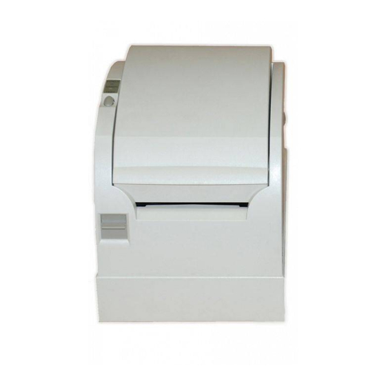
1. Appearance and Names of Components Control panel This panel contains status lamps and operating switches. Top cover Open and close this cover to replace forms. Power switch Cover open lever This switch turns printer power on and off. Pushing this lever down opens the top cover. - Page 5 Interface connector (Serial interface) Drawer kick connector Power connector Interface connector (Parallel interface) Interface Connector (USB Interface Type-B) Power connector Interface Connector Drawer kick connector (USB Interface Type-A)
-
Page 6: Consumable Parts And Ac Adapter
2. Consumable Parts and AC Adapter Use the Thermal paper specified below. Using an AC adapter other than the specified model might cause a malfunction, fire, or electrical shock. 2-1. Roll Paper specification (Thermal paper) (1)Paper width: 80 -1.0 (2)Outer roll diameter: 75~90µm φ102mm or less 90~150µm φ90mm or less (3)Thickness : 75~150µm (4)Core outer/inner diameter... -
Page 7: Ac Adapter
Note: Do not use a paper roll with frayed ends (rough paper edges). Otherwise, a printer error might occur. Depending on the type and thickness of the paper, it may be necessary to change the setting for print density. 2-2. AC adapter (option) Model name : CA02485-0020 Input : 100 to 240V AC, 50/60Hz Output : DC24V±5%, 1.5A... -
Page 8: Connecting Cables And Ac Adapter
3. Connecting Cables and AC Adapter To connect or disconnect these cables, turn off the power switches of the printer and all the devices to be connected to the printer, and then unplug the plug of the AC adapter power cable from the electrical outlet. -
Page 9: Connecting The Drawer Kick Cable
Connector Cover USB Interface Cable Type-A USB Interface Cable Type-B 3-2. Connecting the Drawer Kick Cable Remove the connector cover at the rear of the printer. And connect the drawer kick cable to the rear connector. Note: Remove notch of connector cover with Nipper, to maintain the space for the cable of drawer kick cable. -
Page 10: Connecting The Ac Adapter
3-3. Connecting the AC Adapter Note: To connect or disconnect the AC adapter, turn off the power switches of the printer and all the devices to be connected to the printer. Then, unplug the plug of the AC adapter power cable from the electrical outlet. -
Page 11: Turning On The Power
3-4. Turning on the Power After the AC adapter is connected as explained in Section 3-3, "Connecting the AC Adapter," turn on the power switch at the side of the printer. The POWER lamp on the control panel lights. Power switch... -
Page 12: Control Panel
4. Control Panel 4-1. Control Panel POWER LED lamp Lights when the power switch is turned on and power is supplied to the printer. ERROR LED lamp Lights or blinks to indicate errors. FEED switch Pressing this switch once advances the paper one line. -
Page 13: Loading The Roll Paper
5. Loading the Roll Paper 5-1. Loading the roll paper (1)Push the cover open lever down, and open the top cover. Note: Thermal Head may be broken when Static Electricity impressed. Do not touch Thermal Head. (2) Peel off the pasted end of a new roll of paper. Note: Because the printer cannot print on the pasted portion, remove it completely. - Page 14 Notes: 1. Do not use paper rolls that are deformed as shown below. Otherwise, a printer error, paper jam, or misaligned printing might occur. 2. If a paper roll is loose as shown below, remove any slack before using it. Using loose paper might cause a printer error, paper jam, or misaligned printing.
- Page 15 (4) Place the paper in the correct orientation, and carefully close the top cover. Notes: 1. Place the paper in the correct orientation. If the top cover is closed while the paper is not correctly in place, a paper jam or misaligned printing might occur.
-
Page 16: Removing The Paper Roll
5-2. Removing the Paper Roll (1) Push the cover open lever down, and open the top cover. Note: Thermal Head may be broken when Static Electricity impressed. Do not touch Thermal Head. (2) Remove the paper roll. -
Page 17: Preventing And Clearing Paper Jams
6. Preventing and Clearing Paper Jams 6-1. Preventing Paper Jams Do not touch the paper during ejection or before the paper is completely cut. Holding or pulling the paper by hand during ejection might cause a paper jam, incorrect cutting, or a feed error. 6-2. -
Page 18: Periodic Cleaning
7. Periodic Cleaning Print dropout might be caused by the presence of paper powder or dust. To avoid this problem, remove any black deposits of paper powder and dust from the paper holder, paper feed section, platen roller, and thermal head surfaces. This cleaning should be performed once a month, or as needed. -
Page 19: Conditions For Use
8. Conditions for Use (1) High-duty printing might cause blurred printing. Use an appropriate duty that does not cause blurs. (2) To print an external character set, a bold font (e.g., Gothic) or bold lines should be selected. If a fine font (e.g., Mincho) or fine lines are selected, the print density might be insufficient. - Page 20 PAGES printing method, which needs paper reverse operation at only one time. (17) To use the FP-410 printer in a Microsoft® Windows NT® environment, install the print processor. For an explanation of installation of the print processor, see "Setting the Print Processor"...
- Page 21 (21) USB Device Driver is for Windows 98/Me. Use the standard driver for Windows 2000. (22) The USB version of the FP-410 does not work under Windows 95 or Windows NT4.0. Microsoft® Windows NT® is a registered trademark of Microsoft...
- Page 22 INHALTSVERZEICHNI 1. Erscheinung und Teilebezeichnungen..............21 2. Wärmeempfindliches Papier..............23 2-1. Einzelblatt-Spezifikationen ..............23 2-2. Wechselstromadapters................ 23 3. Kabelanschluss an einen Wechselstromadapter........24 3-1. Anschließen des Schnittstellenkabels ..........24 3-2. Anschließen des Einschub-Kick-Kabels ..........25 3-3. Anschließen des Wechselstromadapters ..........26 3-4.
-
Page 23: Erscheinung Und Teilebezeichnungen
1. Erscheinung und Teilebezeichnungen Bedienfeld Dieses Feld enthält Statusleuchten und Bedienschalter. Obere Abdeckung Diese Abdeckung öffnen und schließen, um das Papier zu ersetzen. Stromschalter Hebel zur Öffnung Dieser Schalter schaltet die der Abdeckung Stromzufuhr ein und aus. Drücken dieses Hebels nach unten öffnet die obere Abdeckung. - Page 24 Schnittstellenanschluss (serielle Schnittstelle) Einschub-Kick- Anschluss Stromschalter Schnittstellenanschluss (parallele Schnittstelle) Schnittstellenanschluss (USB-Schnittstelle Typ-B) Stromschalter Schnittstellenanschluss Einschub-Kick-Anschluss (USB-Schnittstelle Typ A)
-
Page 25: Wärmeempfindliches Papier
2. Wärmeempfindliches Papier Bitte das unten angegebene wärmeempfindliche Papier benutzen. Das Benutzen eines anderen Wechselstromadapters als des unten angegebenen Modells kann Fehlfunktionen, Feuerausbruch oder Stromschlag führen. 2-1. Einzelblatt-Spezifikationen (Wärmeempfindliches Papier) (1)Papierbreite: 80 -1.0 (2)Maximaler äußerer Durchmesser 75~90µm : φ102mm oder weniger 90~150µm : φ90mm oder weniger (3)Papierdicke unter : 75~150µm (4)Kerndurchmesser... -
Page 26: Kabelanschluss An Einen Wechselstromadapter
3. Kabelanschluss an einen Wechselstromadapter Um diese Kabel anzuschließen oder abzustecken, schalten Sie die Stromschalter Druckers auch alle angeschlossenen Geräte. Anschließend ziehen Wechselstromadapter aus der Steckdose. 3-1. Anschließen des Schnittstellenkabels Entfernen Sie die Anschlussabdeckung an der Rückseite der Abdeckung, und schließen Sie das Schnittstellenkabel an den hinteren Anschluss an. -
Page 27: Anschließen Des Einschub-Kick-Kabels
Anschlussabdeckung USB- Schnittstellenkabel Typ A USB- Schnittstellenkabel Typ B 3-2. Anschließen des Einschub-Kick-Kabels Entfernen Sie die Anschlussabdeckung an der Rückseite der Abdeckung, und schließen Sie das Einschub-Kick-Kabel an den hinteren Anschluss. Hinweis: Stellen Sie sicher, dass die Anschlussabdeckung entfernt wird. Wenn die Anschlussabdeckung nicht entfernt wird, bevor das Einschub-Kick-Kabel angeschlossen wird, könnte das Kabel beschädigt werden und so zu einer Fehlfunktion führen. -
Page 28: Anschließen Des Wechselstromadapters
3-3. Anschließen des Wechselstromadapters Hinweis: Um den Wechselstromadapter anzuschließen oder abzustecken, schalten Sie die Stromschalter des Druckers und aller anderen Geräte, die an ihn anzuschließen sind, ab. Dann stecken Sie den Stecker des Wechselstromadapters aus der Steckdose aus. (1)Schließen Sie den Wechselstromadapter an dessen Stromkabel an. Hinweis: Benutzen Sie nur den angegebenen Wechselstromadapter und das dafür angegebene Stromkabel. -
Page 29: Einschalten Der Stromzufuhr
3-4. Einschalten der Stromzufuhr Nachdem der Wechselstromadapter angeschlossen wurde, wie in Abschnitt 3-3, "Anschließen des Wechselstromadapters" erklärt, schalten Sie den Stromschalter an der Seite des Druckers an. Die Power-Leuchte auf dem Bedienfeld leuchtet auf. Stromschalter... -
Page 30: Anzeigeleuchten Und Schalter
4. Anzeigeleuchten und Schalter 4-1. Bedienfeld POWER-Leuchte Leuchtet auf, wenn der Stromschalter eingeschltet und der Drucker mit Strom versorgt wird. ERROR-Leuchte Leuchtet auf oder blinkt, um Fehler anzuzeigen. FEED-Schalter Einmaliges Drücken dieses Schalters schiebt das Papier um eine Zeile weiter (d.h. -
Page 31: Papier Einfüllen
5. Papier einfüllen 5-1. Papier einfüllen (1)Hebel zum Öffnen der Abdeckung nach unten drücken, um die obere Abdeckung zu öffnen. (2)Das geklebte Ende einer neuen Papierrolle abziehen. Hinweis: Da der Drucker auf den geklebten Teil der Papierrolle nicht drucken kann, entfernen Sie diesen vollständig. (3)Setzen Sie die Rolle, wie unten gezeigt, ein und ziehen Sie das vordere Ende der Rolle nach vorne. - Page 32 Hinweis: 1. Keine Papierrollen benutzen, die wie eine der unten gezeigten entstellt sind. Sonst könnten Druckerfehler, Papierstaus oder ungerade Ausdrucke die Folge sein. 2. Wenn eine Papierrolle lose ist, wie unten gezeigt, entfernen Sie jeden Schlupf vor deren Benutzung. Verwendung loser Papierrollen kann zu Druckerfehlern, Papierstaus oder ungeraden Ausdrucken führen.
- Page 33 (4)Richten Sie das Papier richtig aus und schließen Sie dann vorsichtig die obere Abdeckung. Hinweise: 1.Richten Sie das Papier richtig aus. Wenn die obere Abdeckung geschlossen wird, obwohl das Papier nicht richtig ausgerichtet ist, können ein Papierstau oder ein schiefer Ausdruck die Folge sein. 2.Um die obere Abdeckung zu schließen, drücken Sie den Mittelteil (siehe unteren Pfeil) der Abdeckung bis sie sicher verriegelt.
-
Page 34: Entfernen Der Papierrolle
5-2. Entfernen der Papierrolle (1) Drücken Sie den Hebel zur Öffnung der oberen Abdeckung nach unten und öffnen Sie die obere Abdeckung. (2) Entfernen Sie die Papierrolle. -
Page 35: Verhindern Von Papierstaus Und Deren Entfernung
6. Verhindern von Papierstaus und deren Entfernung 6-1. Verhindern von Papierstaus Berühren Sie das Papier nicht während es ausgegeben wird oder bevor es vollständig abgeschnitten wurde. Halten oder Ziehen des Papiers mit der Hand während es ausgegeben wird, kann einen Papierstau, fehlerhaften Schnitt... -
Page 36: Periodische Reinigung
7. Periodische Reinigung Druckausfälle können durch das Vorhandensein von Papierstaub verursacht werden. Um dieses Problem zu vermeiden, entfernen Sie jedwelche schwarze Papierablagerungen und -staub von dem Papierhalter, dem Papierzufuhrfach, der Druckwalze und den Flächen des Thermodruckkopfes. Diese Reinigung sollte einmal im Monat durchgeführt werden. -
Page 37: Benutzungsbedingungen
8. Benutzungsbedingungen (1) Eine sehr intensive Druckauslastung über längere Zeit könnte zu undeutlichem Druck führen. Benutzen Sie eine Druckauslastung, die zu befriedigenden Ergebnissen führt. (2) Um einen externen Zeichensatz zu drucken, sollte eine fette Schrift (z.B. Gothic) oder fette Linien gewählt werden. Wenn ein feine Schrift (z.B. - Page 38 Enden. Sonst könnte die Papierführung des Rahmens abgenutzt werden, wodurch dann Schneidefehler auftreten würden. (14) Um den FP-410-Drucker in einer Microsoft® Windows NT® -Umgebung zu benutzen, installieren Sie den Druckprozessor. Für eine Erklärung der Druckprozessorinstallation, siehe "Einstellen des Druckprozessors"...
- Page 39 Wechselstromadapter mit den entsprechend bezeichneten. (16) Typ-A entspricht USB1.1 High(12Mbps) und Low(1.5Mbps) Geschwindigkeitsmodus. (17) Siehe Datei "FP-410 USB Device Driver Install Guide.pdf" auf der Floppy Disk für die Installationsprozedur des USB-Gerätetreibers. (18) Der USB-Gerätetreiber ist für Windows 98/Me. Benutzen Sie den Standardtreiber für Windows 2000.
- Page 40 Appendix A: Specifications A-1. General Specifications (1) Print method: Direct line thermal printing system (2) Maximum print speed: 180mm/s (single-color thermal paper) 80mm/s (two color thermal paper) (3) Dot resolution: 8 dots/mm (0.125mm) (4) Relationship between number of print columns and character size 48 column printing 42 column printing ANK: Font A...
- Page 41 (7) Outline drawing...
-
Page 42: A-3. Specifications Of Paper Supply
A-2. Cutter Specifications Cutting method: Partial cut (A portion of the paper is not cut). Note: Full-cut mode is not supported. A-3. Specifications of Paper Supply (1) Supply method: Manual placement (2) Paper near-end: Detection of paper near end. A-4. Specifications of Interfaces (1) RS-232C (2) Conforms to IEEE1284 (3) USB... -
Page 43: A-6. Specifications Of Reliability
A-6. Specifications of Reliability a) Printer life Feed of 25 million lines (Specified thermal paper) or 5 years b) Head Running life: 150km (Specified single-color thermal paper) 75km (Specified dual-color thermal paper) Pulse life: 150 million pulses c) Cutter 2,000,000 cuts (Specified thermal paper 75µm) 500,000 cuts (Specified thick thermal paper 150µm) 200,000 cuts (Specified label thermal paper) A-7. - Page 44 Note: 1. As there is a variation in the paper cut position, please leave a gap of at least 4mm centered on the cut position when formatting printing. 2. When formatting print for the white detection area, please follow the following reflective indices: -Black mark reflective index: 15% or less.
-
Page 45: Appendix B: Interface
Appendix B: Interface B-1. Serial Interface Specifications of transmission interface Applicable line Leased direct line Transmission speed 2400,4800,9600,19200,38400,57600 bps (Specified at setup) Communication system Full duplex Synchronization system Start-stop type Connection method Asynchronous response system Transmission code type 7-bit or 8-bit code Transmission code Start bit length: 1 bit, Stop bit length: 1 bit... - Page 46 RS-232C connector Pin No. Signal Function name direction Frame ground Output Send data Input Receive data Output Send request Input Send permission Input Data set ready Signal ground 8 to 12 N.C. Unused Input +24 V ground Input +24 V ground 15 to 17 N.C.
- Page 47 Connection cables (1) The following cable connection configuration is recommended: Printer Host FG < >FG TXD< >TXD RXD< >RXD RTS< >RTS CTS< >CTS DSR< >DSR DTR< >DTR SG < >SG (2) To supply power via the interface connector, use a cable with suitable wire diameter and length so power is not reduced.
-
Page 48: B-2. Parallel Interface
B-2. Parallel Interface (1) Forward channel Signal name Pin No. Signal name direction direction *STROBE Input *STROBE-RET DATA1 Input DATA1-RET DATA2 Input DATA2-RET DATA3 Input DATA3-RET DATA4 Input DATA4-RET DATA5 Input DATA5-RET DATA6 Input DATA6-RET DATA7 Input DATA7-RET DATA8 Input DATA8-RET *ACKNLG Output... - Page 49 (2) Reverse channel Signal name Pin No. Signal name direction direction HostClk Input HostClk-RET DATA1 Input DATA1-RET DATA2 Input DATA2-RET DATA3 Input DATA3-RET DATA4 Input DATA4-RET DATA5 Input DATA5-RET DATA6 Input DATA6-RET DATA7 Input DATA7-RET DATA8 Input DATA8-RET PtrClk Output PtrClk-RET PtrBusy Output...
-
Page 50: B-3. Usb Interface
B-3. USB Interface (1) Type-B Connector: 4Pin Item Signal Name I/O direction Function BUS5V BUS-POWER5V D-inB In/Out D+inB In/Out Grand (2) Type-A Connector: 8Pin Item Signal Name I/O direction Function USB5V2 +5V for A1 D-OUTA2 In/Out D- for A2 D+OUTA2 In/Out D+ for A3 Grand for A4... - Page 51 <Drawer connection 1> Printer Cable Drawer Drawer kick solenoid (24 Ω minimum) Drawer open/close switch Notes: 1. Use a shielded drawer cable. 2. Two drives cannot be driven simultaneously. 3. The drawer on/off time must be specified using t1 and t2 in the pulse generation command (ESC p m t1 t2).
- Page 52 <Drawer connection 2> Drawer 1 Printer Cable Drawer open/close switch Drawer kick solenoid (24 Ω minimum) Drawer 2 Drawer open/close switch Drawer kick solenoid (24 Ω minimum)
-
Page 53: B-5. Specifications Of Power Supply
B-5. Specifications of Power Supply (1)Operating voltage: DC 24V±10% (2)Current consumption -Standby: 0.3 A (on average) Note: Maximum drawer kick drive current: 1 A Two drawer kicks must not be driven simultaneously. -Average current consumption Operating: 1.5 A (at 24 V, 25ºC, print density setting 100%, paper width 80 mm, print duty 9%) Arrangement of power connector pins... -
Page 54: Appendix C: Special Modes
Appendix C: Special Modes C-1. Test Printing Turn off the printer power switch, put the paper in place, and turn on the printer power switch while holding down the FEED switch on the control panel. The data below is printed. When "Test print" is printed, press the FEED switch for about two seconds to start the test printing. -
Page 55: C-2. Hex Dump
C-2. HEX Dump Turn off the printer power switch, put the paper in place, and turn on the printer power switch while holding down the FEED switch on the control panel. The printing described in Section 8.1 occurs. Press the FEED switch for a short time. After "HEX dump" is printed as shown below, press the FEED switch for about two seconds to start the HEX dump mode. -
Page 56: C-3. Setting Up The Printer
C-3. Setting up the Printer (1) Turn off the printer power switch, put the paper in place, and turn on the printer power switch while holding down the FEED switch on the control panel. Press the FEED switch for a short time. When "Setup"... - Page 57 MEMORY SWITCH RETURN TO SETUP MENU :Setup group items OTHER SERIAL INTERFACE CONDITION CUSTOMIZE VALUE MEMORY SWITCH SELECTION ITEM POWER ON STATUS :Setup items RETURN TO SETUP MENU (of memory switch) RETURN TO UP COVEROPEN ERROR BM CHECK AT POW-ON •...
- Page 58 Setup Items (1) MEMORY SWITCH setup items Item Explanation Detail Setup Item POWER ON -Specifies reporting the power-on ENABLE STATUS state. DISABLE RECEIVE -Specifies the capacity of the receive 45BYTE BUFFER buffer. 4KBYTE BUSY -Specifies conditions that determine BUFFERFULL CONDITION the printer busy status.
- Page 59 Note: If connecting this product to a Windows PC via the serial interface, do not select "DSR(#6)RESET: ENABLE ." If "Valid" is selected, this product might not operate even if the printer power is turned on. In this case, turn off the power, disconnect the interface cable from the printer, turn the power back on, and select "DSR(#6)RESET: DISABLE"...
- Page 60 -Returns to the selection mode for the setup group items. RETURN TO -Returns to the setup mode menu. SETUP MENU Address your comments and inquiries on this manual to: FUJITSU ISOTEC LIMITED 135 Higashinozaki Hobara-Machi Date-gun, Fukushima JAPAN TEL: (81-24)574-2224 FAX: (81-24)574-2244...