Advertisement
Quick Links
Project 38
Copyright © 2022 by ELENCO
Electronics, LLC. All rights reserved. No part of this book shall be reproduced by any means; electronic,
®
photocopying, or otherwise without written permission from the publisher. Source Code: SCG-225V1
Visit https://shop.elenco.com/consumers/
https://shop.elenco.com/consumers/
Visit
snap-circuits-green-energy.html
snap-circuits-green-energy.html
to download projects 39-133
to download projects 39-133
Rev B 753170
Advertisement

Related Manuals for Elenco Electronics Snap Circuits Green Energy SCG225


Summary of Contents for Elenco Electronics Snap Circuits Green Energy SCG225
- Page 1 Project 38 Visit https://shop.elenco.com/consumers/ https://shop.elenco.com/consumers/ Visit snap-circuits-green-energy.html snap-circuits-green-energy.html to download projects 39-133 to download projects 39-133 Copyright © 2022 by ELENCO Electronics, LLC. All rights reserved. No part of this book shall be reproduced by any means; electronic, ® photocopying, or otherwise without written permission from the publisher. Source Code: SCG-225V1 Rev B 753170...
-
Page 2: Basic Troubleshooting
Table of Contents For the best learning experience, do the projects in order. Basic Troubleshooting DO’s and DON’Ts of Building Circuits Parts List Advanced Troubleshooting 10 - 11 How to Use It 3 - 4 Projects 1 - 38 12 - 30 About Your Snap Circuits Green Parts 5 - 7... - Page 3 Parts List (colors and styles may vary) Symbols and Numbers Qty. Name Symbol Part # Qty. Name Symbol Part # Base Grid (11” x 7.7”) 6SCBGGR Black Jumper Wire 6SCJ1 Green Color 1-Snap Wire 6SC01 Red Jumper Wire SCCJ2 2-Snap Wire 6SC02 Liquid Holder 6SCLH...
- Page 4 How to Use It Snap Circuits uses building blocks with A large clear plastic base grid is included Sometimes the crank arm will be ® snaps to build the different electrical and with this kit to help keep the circuit blocks mounted on the geared motor (GM) to electronic circuits in the projects.
- Page 5 How to Use It Whenever the motor (M4) is used, it will Assembling the Liquid Power Source: If the copper and zinc electrodes get have the wind fan or the water wheel corroded through use, use sandpaper, placed on top; simply push the fan onto steel wool, or a scraper to remove the the shaft.
-
Page 6: About Your Snap Circuits
About Your Snap Circuits Green Parts ® base grid (like the projects using water). arranged in layers that cancel each other BASE GRID out. When sunlight shines on it, charged Wires transport electricity just like particles in the light unbalance the silicon pipes are used to transport water. - Page 7 About Your Snap Circuits Green Parts ® flows through the coil, it creates a METER magnetic field. The interaction of the Meter (M6) two magnetic fields causes the coil (connected to the pointer) to move (deflect). Pointer Wind Fan Water Wheel Magnet How does electricity turn the shaft in the motor? The answer is magnetism.
- Page 8 About Your Snap Circuits Green Parts ® GEARED MOTOR RED & YELLOW LEDs OTHER PARTS Geared Motor Melody IC (U32) The color LED (D8) and red/yellow bicolor & Crank Arm LED (D10) are light emitting diodes, and may be thought of as a special one-way light bulbs. In the “forward”...
- Page 9 Introduction to Electricity What is electricity? Nobody really knows. We only know how tiny distances. Try to imagine a plumbing structure of the same to produce it, understand its properties, and how to control it. complexity as the circuitry inside a portable radio - it would have to Electricity is the movement of sub-atomic charged particles (called be large because we can’t make water pipes so small.
-
Page 10: Do's And Don'ts Of Building Circuits
For example, the order of website at www.elenco.com/for-makers. Send your suggestions to parts connected in series or in parallel does not matter — what matters Elenco Electronics: elenco@elenco.com. is how combinations of these sub-circuits are arranged together. Elenco provides a circuit designer so that you can make your own ®... -
Page 11: Advanced Troubleshooting
Advanced Troubleshooting (Adult supervision recommended) meter settings do not, then the meter meter pointer does not move, then test Elenco Electronics is not responsible ® is damaged. the snap wires one at a time to find the for parts damaged due to incorrect damaged one. - Page 12 Advanced Troubleshooting (continued) Battery (B4): Plug B4 into a powered Switcher (S6): Build this circuit USB port; the “USB POWER” light on and place the solar cell (B7) near B4 should come on, indicating that it the same light source you used in is being charged by the USB.
- Page 13 PROJECT 1 • Hand Cranking Build the circuit shown by placing all the parts with a black 1 next to them on the clear plastic base grid first. Then, assemble parts marked with a 2. Be sure to place the parts with their (+) side oriented as shown.
- Page 14 PROJECT 3 • Best Charging Circuits Your rechargeable battery (B4) will need to be recharged often; it can be charged with a USB connection or with solar light using any of these circuits. Although the battery is rated as 3.6V, it may charge The USB POWER light on B4 comes on when it is charging through the USB.
- Page 15 PROJECT 4 • Solar Power Assemble the pivot, mount the solar cell (B7) on it, and place it in the circuit as shown. Place all the parts with a black 1 next to them on the clear plastic base grid first, then parts marked with a 2. The red/yellow LED (D10) may be connected in either direction.
- Page 16 PROJECT 7 • Solar Charger 5mA Assemble the pivot, mount the solar cell (B7) on it, and Solar energy is place it in the circuit as shown. Connect the solar cell to free, abundant and the circuit using the red and black jumper wires. Place the causes no pollution.
- Page 17 PROJECT 9 • Windmill Assemble the pivot stand, mount the wind fan on the motor (M4), mount the motor on the pivot, place the pivot on the base grid and connect it to the meter (M6) using the red and black jumper wires. Set the meter to the 5V setting.
- Page 18 PROJECT 11 • Multi Power Build the circuit shown and set the meter to the 5V setting. Set the switcher to the middle position and the meter measures the voltage produced by the solar cell. Next, set the switcher to the left position and blow on the windmill to see the voltage it produces.
- Page 19 PROJECT 13 • Electric Circuit Educational Corner: What is really happening here? 1. The battery (B4, containing a 3.6V rechargeable battery with protection Build the circuit shown and circuitry) converts chemical energy into electrical energy and “pushes” push the press switch (S2) it through the circuit, just like the electricity from your power company.
- Page 20 PROJECT 14 • Close the Door The “on” position of a switch is also called the “closed” position. Similarly, the “off” position is also called the Build the circuit shown. The switcher (S6) and “open” position. This is because the symbol for a press switch (S2) control the lights.
- Page 21 PROJECT 16 • Reverser Build the circuit shown. Use the switcher (S6) to control the light. See project 3 if you need to recharge the battery (B4). The switcher (S6) is actually a complex switch used to reverse the wires to a component or circuit.
- Page 22 PROJECT 18 • Voltage Build the circuit shown. Set the meter (M6) to the 5V setting. Push the switch (S2) to connect the meter to the battery and measure its voltage. Electricity is the movement of sub- won’t turn on; if too high then the bulb atomic charged particles (called will overheat and burn out.
- Page 23 PROJECT 20 • Light Emitting Diode Build the circuit shown. Set the meter (M6) to the 0.5mA setting. For the upper and lower switcher (S6) positions, push the press switch (S2) to measure the current through one of the LEDs (D8 & D10). Then change the switcher to measure the current with the other LED, and compare them.
- Page 24 PROJECT 22 • Clock Build the circuit shown. Set the meter (M6) to the 0.5mA setting. The clock display will light, but the meter will not measure any current. See page 4 if you would like to set the time. 0.5mA The clock needs only about 0.005mA of current to operate, and this is too small to measure on your meter.
- Page 25 PROJECT 24 • Motor 50mA Build the circuit shown. Set the meter (M6) to the 50mA setting and place the wind fan on the motor (M4). Push the press switch (S2) and watch the current on the meter as the motor speeds up.
- Page 26 PROJECT 27 • Crank Motor Build the circuit shown. Set the meter (M6) to the 50mA setting. Push the press 50mA switch (S2) and watch the current on the meter when the crank arm on the geared motor (GM) spins. Replace the geared motor with the motor (M4) and wind fan, red/yellow LED (D10), color LED (D8, “+”...
- Page 27 PROJECT 29 • Fade Out Set the switcher (S6) to the top or bottom position. Watch as one LED fades out after a few seconds, then set the switcher to the other side. Do this several times. The 470μF capacitor (C5) stores electricity, and keeps the disconnected LED on for a few seconds after you flip the switch.
- Page 28 PROJECT 32 • Mini Car with on-Board Control Side view: Top view: Rubber rings Build the circuit as shown, initially setting the switcher (S6) to the middle setting. Mount the 1.75” gear on the geared motor (GM) with the rubber rings to keep it from sliding out of position, place it on the mini car frame, and connect the battery (B4), switcher (S6) and red &...
- Page 29 PROJECT 34 • Liquid Battery Assemble the liquid energy source using the instructions on page 4. Connect the red & black jumper wires between the meter (M6) and the Zinc Copper electrodes, the (+) side of the meter goes to the copper one. Set the electrode electrode meter to the 5V setting.
- Page 30 PROJECT 36 • Cola Light Assemble the liquid energy source using the instructions on page 4. Build the circuit and connect the red & black jumper wires; the red wire goes to the copper electrode. Set the meter (M6) to the 5V setting. Fill the compartments with cola soda (other soda flavors and lemon, tomato, or grapefruit juice also work).
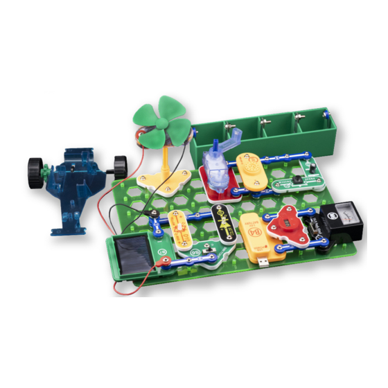
- Page 31 PROJECT 38 • Everything Circuit This project combines several circuits to demonstrate what you can do with Snap Circuits® Green Energy. This circuit may be shown on your box or manual cover. Assemble the circuits shown. Set the meter (M6) to the 5V setting and place the crank arm on the geared motor (GM).
- Page 32 SCG-225 Snap Circuits Green Energy Block Layout ® Important: If any parts are missing or damaged, DO NOT RETURN TO RETAILER. Go to www.elenco.com/replacement-parts or e-mail us at: support@elenco.com. 150 Carpenter Ave. Wheeling, IL 60090 U.S.A. • (847) 541-3800 Note: A complete parts list is on page 2 in this manual. Visit Visit https://shop.elenco.com/consumers/ https://shop.elenco.com/consumers/...