Table of Contents
Advertisement
Quick Links
Instruction Manual
AGES
8 108
Projects 1 - 93
Project 3
Copyright © 2017 by Elenco
Electronics, Inc. All rights reserved. No part of this book shall be reproduced by
753136
®
any means; electronic, photocopying, or otherwise without written permission from the publisher.
U.S. Patents: 7,144,255; 7,273,377, & patents pending
Advertisement
Table of Contents

Related Manuals for Elenco Electronics Snap Circuits STEM


Summary of Contents for Elenco Electronics Snap Circuits STEM
- Page 1 Instruction Manual AGES 8 108 Projects 1 - 93 Project 3 Copyright © 2017 by Elenco Electronics, Inc. All rights reserved. No part of this book shall be reproduced by 753136 ® any means; electronic, photocopying, or otherwise without written permission from the publisher. U.S.
- Page 2 Table of Contents Basic Troubleshooting DOs and DON’Ts of Building Circuits Parts List Advanced Troubleshooting How to Use It Project Listings Assembling the Build-Your-Own Electromagnet Projects 1 - 93 13 - 74 Guidelines for Use in Classrooms & Home School 4 Test Your Knowledge About Your Snap Circuits Parts...
- Page 3 Parts List (Colors and styles may vary) Symbols and Numbers Important: If any parts are missing or damaged, DO NOT RETURN TO RETAILER. Call toll-free (800) 533-2441 or e-mail us at: help@elenco.com. Customer Service ● 150 Carpenter Ave. ● Wheeling, IL 60090 U.S.A. Qty.
- Page 4 How to Use Snap Circuits ® Snap Circuits uses building blocks with snaps You need a power source to build each circuit. Some circuits use the jumper wires to make ® to build the different electrical and electronic This is labeled and requires three (3) 1.5V unusual connections.
- Page 5 How to Use Snap Circuits ® Assembling the build-your-own electromagnet: GUIDELINES FOR USE IN CLASSROOMS OR HOME SCHOOLING: You need the coil, an iron core rod, a grommet, and the 2-spring socket This product is a tool for opening the exciting world of electronics, and its relationship to (?1).
- Page 6 About Your Snap Circuits Parts ® SWITCHES BATTERY HOLDER (Part designs are subject to change without notice). BASE GRID The slide & press switches (S1 & S2) connect The batteries (B3) produce an electrical voltage (pressed or “ON”) or disconnect (not pressed or using a chemical reaction.
- Page 7 About Your Snap Circuits Parts ® METER Inside the meter there is a fixed magnet and a moveable coil around it. As current flows through The meter (M5) is an important measuring de- the coil, it creates a magnetic field. The interac- vice.
- Page 8 About Your Snap Circuits Parts ® ELECTROMAGNET LAMP The iron filings are tiny fragments of iron in a The electromagnet (M3) is a large coil of wire, A light bulb, such as in the 4.5V lamps (L4), con- sealed case. They which acts like a magnet when electricity flows tains a special thin high-resistance wire.
- Page 9 About Your Snap Circuits Parts ® RELAY SCHEMATICS The relay (S3) is an electronic switch with contacts The white LED (D6) is a light emitting diode, and The symbols for the parts shown in that can be closed or opened. It contains a coil that may be thought of as a special one-way light this section are used by engineers in generates a magnetic field when current flows...
- Page 10 Introduction to Electricity What is electricity? Nobody really knows. We only know how to produce it, under- There are two ways of arranging parts in a circuit, in series or stand its properties, and how to control it. Electricity is the movement of sub-atomic in parallel.
- Page 11 DO’s and DON’Ts of Building Circuits Examples of SHORT CIRCUITS - NEVER DO THESE!!! After building the circuits given in this booklet, you may wish to experi- ment on your own. Use the projects in this booklet as a guide, as many Placing a 3-snap wire directly across important design concepts are introduced throughout them.
- Page 12 Advanced Troubleshooting (Adult supervision recommended) ELENCO is not responsible for parts dam- Meter (M5): Build project 85, but replace ® aged due to incorrect wiring. the 3-snap wire with the meter. a. Set the meter to the 5V scale and push If you suspect you have damaged parts, the press switch.
-
Page 13: Table Of Contents
Project Listings (circuits with gold project numbers are the educational summary projects mentioned on page 4) Project # Description Page # Project # Description Page # Project # Description Page # Fun Start Lamps & Motors Motor with Flashes Make Your Own Generator Lots of Lights Light Bulb High Speed Generator... -
Page 14: Lots Of Lights
Lots of Lights Project 1 Placement Level Numbers NOTE: this circuit (and many others in this book) have an LED being used without a resistor or other component to limit the electric current through it. Normally this could damage an LED but your Snap Circuits®... -
Page 15: Electronic Playground
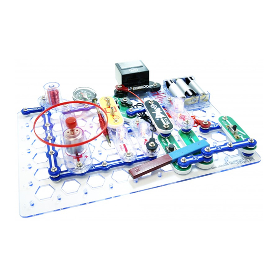
Project 3 Electronic Playground Electronics is the science of working with and controlling electricity. This circuit is shown on the front of the Snap Circuits ® STEM box, use that picture to help in building it. Build the circuit as shown. Set the meter (M5) to the 1A setting. -
Page 16: Static Electricity
Project 4 Static Electricity Note: This project works best on a cold dry day. If These effects are caused by electricity. We call this the weather is humid, the water vapor in the air al- static electricity because the electrical charges are lows the static electric charge to dissipate, and this not moving, although pulling clothes apart sounds like project may not work. - Page 17 Find a comb (or a plastic ruler) and some paper. Rip up the paper Next, hold your magnet near the paper pieces; nothing happens. into small pieces. Run the comb through your hair several times Run the comb in your hair again and place it next to the iron filings case; not much then hold it near the paper pieces to pick them up.
-
Page 18: Light The Way
Project 5 Light the Way What is really happening here? 1. The batteries (B3) convert chemical energy into electrical energy and “push” it through the circuit, just like the electricity from your power company. A battery pushes electricity through a circuit just like a pump pushes water through a pipe. -
Page 19: Ohm's Law
Project 6 Compare the LED current (measured on the meter) to the current with the Light Bulbs of the Future lamp (you can also try it with the meter on the 1mA setting instead of the 1A setting). How do they compare? Use the preceding circuit but replace the lamp (L4) with the white LED (D6, “+”... -
Page 20: Switches
Project 8 Switches The “on” position of a switch is also called the “closed” position. Similarly, the “off” position is also called the “open” po- sition. This is because the symbol for a slide switch is similar to the symbol for a door in an architect’s drawing of a room: Walls Door... -
Page 21: Fuse
Project 9 Fuse Pushing the press switch bypasses the lamp, making the meter the only resistance in the circuit. The meter has very low resistance on its 1A setting, so there is nothing in the circuit to limit the current. When you push the press switch, the high current (>1A) activates a safety fuse in the battery holder (B3) after a few seconds, which lowers the current enough to protect the batteries and... -
Page 22: Materials Tester
Project 10 Materials Tester If you have the build-your-own electromagnet connected to the two-Spring socket (?1), disconnect its wires for this proj- ect. Build the circuit and set the meter (M5) to the 1A setting. Turn on the slide switch (S1) and touch (or connect) various materials between the springs on the two--spring socket See which materials are good at transporting electricity by watching the meter current and lamp (L4) brightness. -
Page 23: Make Your Own Parts
Project 11 Make Your Own Parts Method A (easy): Spread Method B (challenging): Use a SHARP pencil some water on the table (No. 2 lead is best) and draw shapes, such as the into puddles of different ones here. Draw them on a hard, flat surface. shapes, perhaps like the Press hard and fill in several times until you have a ones shown below. -
Page 24: Motor Resistance
Project 12 Motor Resistance Build the circuit, set the meter (M5) to the 1A Calculate the resistance of the motor, setting, and turn on the slide switch (S1). The with and without the fan. How does motor (M1) spins and the meter measures the your calculation of the motor’s resist- current. -
Page 25: Series Circuit (Lamps In Series)
Project 14 Series Circuit Build the circuit, set the meter to the 1A setting, and turn on the slide switch (S1). The three lamps (L4) are dimly lit, and the meter measures the current. How would the current change if you replaced one of the lamps with a 3-snap wire? (Try it.) How would the current change if you replaced two of the lamps with 3-snap wires? (Try it.) -
Page 26: Series Circuit - Voltage
Series Circuit - Voltage Project 15 This circuit is similar to the preceding one, but measures the voltage instead of the current. Build the circuit, set the meter to the 5V setting, and turn on the slide switch (S1). The three lamps (L4) are dimly lit. Snap the loose end of the red jumper wire to points A, B, C, or D to measure the voltage at that point using the meter. -
Page 27: Parallel Circuit
Project 16 Parallel Circuit Build the circuit, set the meter (M5) to the 1A setting, and turn on the slide switch (S1). The lamps (L4) are bright and the meter measures the current. How would the current change if you removed one or two lamps? (Try it.) How would the current change if you replaced one of the lamps with the white LED (D6)? (Try it.) -
Page 28: Parallel Circuit - Voltage
Parallel Circuit - Voltage Project 17 Batteries produce electricity using a chemical reaction, but they have a limited supply of the chemicals, and not all of them can react at once. If the batteries can- not produce as much electricity as a circuit wants, the voltage drops. -
Page 29: Parallel Swapping
Project 18 Parallel Swapping Build the main circuit and set the meter (M5) on the 5V setting. Turn on the slide switch (S1); the lamp (L4) lights and the meter (M5) measures the voltage from the batteries (B3). Part B: move the meter so it’s across location “B” and then location “C”. -
Page 30: Series Swapping
Project 19 Series Swapping Build the main circuit and set the meter (M5) on the 1A setting. Turn on the slide switch (S1); the lamps (L4) light dimly and the meter (M5) measures the current through the circuit. Now swap the positions of any of the lamps, 3-snap wires, the slide switch and the meter (the meter should always be placed so it hangs out of the circuit). -
Page 31: Batteries In Series
Batteries in Series Project 20 Build the circuit, set the meter (M5) to the 5V setting, and turn on the slide switch (S1). Part A Part A: Read the battery voltage on the meter. If your batteries are new then it should be about 4.5V. -
Page 32: Motor At Different Voltages
Project 22 Project 23 Motor at Different Voltages LED at Different Voltages Use the preceding circuit, but LEDs have a turn-on voltage thresh- Use the preceding circuit, but replace the lamp (L4) with the motor replace the motor (M1), with old that must be exceeded before the (M1, “+”... -
Page 33: Double Voltage Shifter
Project 25 Double Voltage Shifter This project is similar to the preceding one, but uses three lamps. Build the circuit, and set the meter (M5) to the 5V setting. The lamps (L4) are on dimly and the meter measures the voltage across the top lamp. Push the press switch (S2) to turn off the bottom lamp. -
Page 34: Fundamentals
Project 26 Double Switching Ammeter This project is similar to the preceding one, but measures current instead of voltage. Build the circuit, and set the meter (M5) to the 1A setting. The lamps (L4) are on dimly and the meter measures the current through the circuit. -
Page 35: Current Divider
Project 27 Current Divider Are the currents through circuit branches B, C, and D the same or different? Add up the currents through circuit branches B, C, and D. How does the total compare to the main circuit current (part A)? Part B Part A: Build the main circuit, and set the meter (M5) to the 1A setting. -
Page 36: Currents 35
3 Currents Project 28 Build the main circuit, and set the meter (M5) to the 1A set- ting. Push the press switch (S2), turn on the slide switch (S1), or set the switcher to the top position (turning it on). Turn on the switches one at a time and in combinations, comparing the current on the meter. -
Page 37: Or Circuit
Project 30 OR Circuit if switch S9, switch S1 OR switch S2 is on then the lamp will be on. Engi- neers refer to this switching combi- nation as an OR sub-circuit (short for “this OR that”). The same type of circuit is used throughout your home, such as having several sensors controlling a security light. -
Page 38: Light Bulb With Meter
Light Bulb with Meter Project 32 This circuit is like the preceding one, but What is the voltage across the top lamp? adds a meter so you can compare the volt- ages across the lamps. Build the circuit, set the meter (M5) to the 5V setting, and turn on the slide switch (S1). -
Page 39: Direction Motor
Project 33 2 Direction Motor Build the circuit. Set the switcher (S6) to the middle position (off), set the meter (M5) to the 1A setting, and place the fan on the motor (M1). Now set the switcher to the top position; the motor spins, the lamp (L4) lights, and the meter measures the current. -
Page 40: 3-Speed Motor
3-Speed Motor Project 34 Build the circuit, set the switcher (S6) to the middle position (off), set the meter (M5) to the 1A setting, and leave the fan off the motor (M1). Push switch (S2); the motor spins, and the meter measures the current. Turn on the slide switch (S1) or set the switcher to the left position to adjust the motor speed. -
Page 41: 3-Speed Motor - Voltage
3-Speed Motor - Voltage Project 35 This circuit is just like the preceding one, except the meter measures the voltage instead of the current. Build the circuit, set the switcher (S6) to the middle position (off), set the meter (M5) to the 5V setting, and leave the fan off the motor (M1). Push switch (S2); the motor spins, and the meter measures the voltage. -
Page 42: 4-Speed Motor
4-Speed Motor Project 37 Build the circuit, set the switcher (S6) to the middle position (off), set the meter (M5) to the 1A setting, and place the fan on the motor (M1). First, set the switcher to the left position to start the motor. -
Page 43: Big Load
Project 39 Big Load Build the circuit, set the switcher (S6) to the middle or lower position (off), set the meter (M5) to the 1A setting, and place the fan on the motor (M1). Set the switcher to the top position to light the lamps (L4), push the press switch (S2) to spin the motor, and turn on the slide switch (S1) to light the white LED (D6). -
Page 44: Holding Down
Project 41 Holding Down Build the circuit. Set the meter (M5) to the 5V scale, place the fan on the motor (M1), and drop the thin rod into the electromagnet (M3). Turn on the slide switch (S1). The fan spins, the lamps (L4) light, and the meter measures the voltage. -
Page 45: (Overloading Batteries) Propellor And Fan (Motor Direction)
Project 42 Propellor and Fan Build the circuit as shown, and set the switcher (S6) to the mid- dle position at first, then set it to the bottom position to spin the fan. The fan blades suck in air around the motor (M1) and push it straight up. -
Page 46: Motor & Lights
Project 43 Motor & Lights Build the circuit, set the meter (M5) to the 5V scale, and turn on the slide switch (S1). The meter measures the voltage across the white LED (D6) and motor (M1). Notice how fast the fan spins, and how bright the lights are. -
Page 47: Compass
Project 45 Compass 1. Hold your compass away from everything, notice that the red arrow always points north. Spin it around, the red arrow will adjust and resume pointing north. The earth’s core is made of iron, which has a magnetic field. The compass points north because it is attracted to this magnetic field. -
Page 48: Magnetic Fields
Project 46 Magnetic Fields A magnet has a magnetic field, and a bat- tery has an electric field. The north and south poles of a magnet are comparable to the positive and negative terminals of a battery. Electric and magnetic fields affect each other. -
Page 49: Electronic Magnet
Project 47 Electronic Magnet Build the circuit shown. Place the iron core rod inside the electromagnet (M3) and secure it with the rubber grommet. Iron Core Rod This project works best if you have new alkaline batteries. Hold the electromagnet near something made of iron and push the switch (S2). -
Page 50: Electromagnet Magnetic Field
Project 48 Electromagnet Magnetic Field Iron Core Rod 1. Use the circuit from the preceding project, with the iron core rod in the electromagnet (M3). An elec- Rubber Grommet tronic magnet has a magnetic field just like an or- dinary magnet. Hold your compass next to the electromagnet and push the press switch (S2). -
Page 51: Electromagnet Tower
Electromagnet Tower Project 49 Build the circuit as shown and drop the thin rod into the electromagnet (M3). Push the press switch (S2) several times. The thin rod gets sucked into the electromagnet and can be suspended there, or you can bounce it up and down. -
Page 52: Electromagnet Direction
Project 50 Electromagnet Direction Build the circuit shown. Place the iron core rod in the electromagnet (M3), and set the meter (M5) to the 1A scale. Set the switcher (S6) to the top or bottom position. The meter shows a current is flowing and the compass needle is attracted to the electromagnet. -
Page 53: Better Wire Magnet
Project 52 Better Wire Magnet FOR ADVANCED USERS - ADULT SUPERVISION RECOMMENDED Build the circuit. Place the rubber grommet on one end of the iron core rod and wrap the red jumper wire tightly around it, as shown. Connect the red jumper wire to the circuit. -
Page 54: Build-Your-Own Electromagnet
Project 53 Build-Your-Own Electromagnet The wire magnet in the preceding circuit is not very powerful because it only has a few loops of wire, but you can make a better one. Assemble the build-your-own electromagnet (the thin wire wrapped around an iron core rod, with the ends con- nected to the 2-spring socket (?1)) using the instructions on page 5. -
Page 55: Magnetic Induction
Project 55 Magnetic Induction Build the circuit as shown. Place the iron core rod into the electromagnet (M3) and set the meter (M5) to the 1mA scale. A. Move the magnet left-right or up-down near the electromagnet. You may see the meter pointer wiggle, which indicates a small current. -
Page 56: (Currents In A Series Circuit)
Project 57 Electromagnet Challenge This circuit isn’t really a fair Assemble the build-your-own electromagnet comparison between the (the thin wire wrapped around an iron core rod, build-your-own and M3 elec- with the ends connected to the 2-spring socket tromagnets, because the (?1)) using the instructions on page 5. -
Page 57: Generator 56
Project 59 Generator SET THE SWITCHER (S6) TO THE MIDDLE POSITION BEFORE COMPLET- ING THE CIRCUIT. Build the circuit as shown, leave the fan off the motor (M1). Set the meter (M5) to the 5V scale for now. Set the switcher to the right position to get the motor spinning, then set it to the left position and watch the meter to see how much voltage is produced. -
Page 58: Motor With Flashes
Project 61 Motor with Flashes Build the circuit shown and watch the white As the motor shafts spins it pro- LED (D6) as you push and release the duces small voltage spikes (both press switch (S2). Notice that even though positive and negative), which can the LED is connected backwards, it is flash- be enough to dimly light the LED. -
Page 59: High Speed Generator
Project 63 High Speed Generator FOR ADVANCED USERS - ADULT SUPERVISION RECOMMENDED Build the circuit and set the meter (M5) to the 1mA scale. Using the string, make a small loop at one end and put it on a prong of the motor (M1) top. Wind a few feet of the string around the motor shaft (wind it so that pulling the string will spin the motor shaft clockwise). -
Page 60: (Or Gate With Switches)
Relay Magnetic Energy Released Project 65 Build the circuit, then push and release the press switch (S2) while watching the white LED (D6). The relay (S3) has a coil with a mag- netic field, just like the electromagnet (M3). The lamp does not have a coil or a magnetic field. -
Page 61: Reed Switch With Electromagnet
Project 67 Reed Switch with Electromagnet Build the circuit as shown, and turn on the slide switch (S1). The electromagnet (M3) should be activating the reed switch (S9), which turns on the white LED (D6). Raise the iron core rod in the electromagnet (or remove the rod) to turn off the LED. You can also remove the electromagnet and instead connect it to the circuit using the red & black jumper wires, then hold it near the reed switch to turn on the LED. -
Page 62: Relay
Project 69 Relay Relays are electronically controlled switches, which allow a low-voltage circuit to control a high-voltage or high-current circuit. Relays use magnetism to open or Coil close a mechanical switch. Look at the relay symbol in the drawing. Contacts 1-3: The relay contains a coil, and a set of contacts that are switched when Coil is off: 1-2 connected... -
Page 63: Relay Buzzer
Project 70 Relay Buzzer The sound is caused by the relay’s con- tacts opening and closing at a fast rate. Build the circuit and turn on the slide switch (S1). Look at the “1-2-3” marking on the relay The relay (S3) makes a buzzing sound. symbol in the drawing. -
Page 64: Alternating Voltage
Project 72 Alternating Voltage Build the circuit as shown (leave the fan off the motor), and turn on the slide switch (S1); you hear a buzzing sound as the relay (S3) turns on and off rapidly. Set the switcher (S6) to the top or bottom position to turn on the motor (M1) and white LED (D6). -
Page 65: Transformer (Build A Transformer)
Project 74 Transformer Build the circuit as shown. Assemble the build-your-own electromagnet as per the instructions on page 5. Push the wire on the build-your-own electromagnet to one side and insert its iron rod into the top of the elec- tromagnet (M3), as shown. -
Page 66: Relay Memory
Project 75 Relay Memory Build the circuit and turn on Why is the lamp off until you push the press switch? the slide switch (S1). Noth- ing happens. Now push the press switch (S2). The lamp (L4) comes on and stays on Why does the lamp stay on after you release the even after you release the press switch? (Look at the explanation of how the... -
Page 67: (Adjusting Motor Speed With Lamps)
Project 77 Build Your Own Relay FOR ADVANCED USERS - ADULT SUPERVISION RECOMMENDED Note spring Build the circuit shown. Three 3-snaps are stacked together direction of at base grid location E4-E6. Snap the 4-snap onto the 1- 1-snap snap at grid location D2, then place it so it lays on the snap at F4 (DO NOT SNAP IT ON). -
Page 68: Build Your Own Buzzer
Build Your Own Buzzer Project 78 FOR ADVANCED USERS - ADULT SUPERVISION RECOMMENDED Build the circuit shown. At base grid location B6-B8, 3-snaps are on levels 1, 3 and 4. Snap the 4-snap onto the 1-snap at A4, then place it so it lays on the snap at C6 (DO NOT SNAP IT ON). Snap the nut-snap on the 4-snap so it will be under the electromagnet (M3). -
Page 69: Cola Power
Project 80 Cola Power You can buy a cola-powered clock. Set the meter (M5) to the 1mA scale and Cola-flavored soda is lightly connect the jumper wires to it. Connect the acidic.The acid is similar to other ends of the jumper wires to the snap the material used in some electrodes (red to copper), and place them types of batteries, though... -
Page 70: Water Impurity Detector
Project 82 Water Impurity Detector Set the meter (M5) to the 1mA scale and connect the jumper wires to it. Connect the other ends of the jumper wires to the snap electrodes (red to copper), and place them in a cup of water. -
Page 71: (Load Effect On Battery Voltage)
Project 83 Swing the Magnet Build the circuit shown and place the iron core rod in the electro- magnet (M3). Tie the magnet to a string and hold it just above the electromagnet, so that the magnet is attracted to the iron core rod without touching it. -
Page 72: Morse Code
Project 85 Morse Code This simple circuit can be used for communication. Push the press switch (S2) in long and short bursts to make a pattern of light flashes rep- resenting the dots and dashes shown in the Morse Code table shown. You can use Morse Code and this circuit to send secret messages to some friends in the room without others knowing what you’re saying. -
Page 73: Hypnotic Discs (Spin Patterns)
Project 86 Hypnotic Discs Part A Build the circuit as shown. Cut out the red spiral pattern shown and tape it on the fan. Spin the pattern by briefly pushing the press switch (S2). You will see the most interesting effects when the pattern is spinning slowly. Part B Replace the pattern with the colored lines pattern shown. -
Page 74: Spin Draw
Project 87 Spin Draw Use the preceding circuit. Using the fan as a guide, draw a circle on a piece of cardboard or paper. Cut the circle out with scissors and tape it to the fan blade so it can be easily removed later. -
Page 75: 2-Way Circuit
Project 88 2-Way Circuit Build the circuit, set the meter (M5) to the 1A setting, place the iron core rod in the electromagnet (M3), and place the fan on the motor (M1). Set the switcher (S6) to the left or right to make electricity flow through the lights, motor, and electromagnet in opposite directions. -
Page 76: Electromagnet Controlled Switch
Switch Project 90 Electromagnetic Controlled Build the circuit, place the iron core rod in the electromagnet (M3), and turn on the slide switch (S1). Use the red & black jumper wires to hold the reed switch (S9) over the electromagnet to turn on the lamp (L4). You can also activate the reed switch by holding the magnet close to it. -
Page 77: Magnetism & Electromagnetism
Project 92 Magnetic Switcher Build the circuit and turn on the slide switch (S1); the lamp (L4) should be on. Hold the magnet near the reed switch (S9) to activate the relay (S3), which turns the white LED (D6) on and the lamp off. Project 93 Circuits Fun Build the circuit as shown, set the meter (M5) to the... - Page 78 TEST YOUR KNOWLEDGE Answers are at www.snapcircuits.net/scstem1. 1. Electric current is the movement of sub- 14.A fuse shuts down a circuit if the current 26. Connecting several batteries in series re- 38. Most magnets are made of copper. atomic charged particles through a ma- is abnormally high.
- Page 79 Other Snap Circuits Products! ® visit www.elenco.com or call us toll-free at 800-533-2441. For Snap Circuits For a listing of local toy retailers who carry Snap Circuits ® ® accessories, additional parts, and more information about your parts visit www.snapcircuits.net. Model SC-SNAPINO Model SC-3MEG Model SC-3DI...
- Page 80 SC-STEM1 SELECT Block Layout Important: If any parts are missing or damaged, DO NOT RETURN TO RETAILER. Call toll-free (800) 533-2441 or e-mail us at: help@elenco.com. Customer Service ● 150 Carpenter Ave. Wheeling, IL 60090 U.S.A. Note: A complete parts list is on page 2 in this manual.