Table of Contents
Advertisement
Quick Links
Operating Instructions
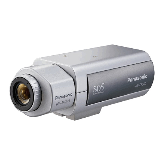
Color CCTV Camera
WV-CP500L/G
Model No.
WV-CP504LE
This illustration represents WV-CP500L/G.
Lens: Option
Before attempting to connect or operate this product,
please read these instructions carefully and save this manual for future use.
The model number is abbreviated in some descriptions in this manual.
Advertisement
Table of Contents

Related Manuals for Panasonic WV-CP500L


Summary of Contents for Panasonic WV-CP500L
- Page 1 Color CCTV Camera WV-CP500L/G Model No. WV-CP504LE This illustration represents WV-CP500L/G. Lens: Option Before attempting to connect or operate this product, please read these instructions carefully and save this manual for future use. The model number is abbreviated in some descriptions in this manual.
-
Page 2: Preface
Preface About the user manuals The operating instructions of the camera consist of 2 sets: these operating instructions (PDF) and Installation Guide. This document explains how to configure the settings of the camera. Refer to the installation guide for further information about how to install the camera. ®... -
Page 3: Table Of Contents
Contents Preface ............................... About the user manuals ......................... Trademarks and registered trademarks ....................About the setup menus ..........................Setup menu list ............................Basic operation ............................Screen transition diagram ........................Camera title setting [CAMERA ID] ......................Camera operation setting [CAMERA SETUP] .................... 1. -
Page 4: About The Setup Menus
About the setup menus Performing each setting item in the setup menu should be completed in advance to use this unit. Perform the settings for each item in accordance with the conditions of the camera shooting area. The following is an example of setup procedure when LANGUAGE is set to ENGLISH. Setup menu list Reference Setup item... -
Page 5: Basic Operation
Basic operation The description below explains how to operate the setup menu basically. The operations in the setup menu are performed with the operation buttons after calling up the setup menu on the connected video monitor. Refer to the installation guide for further information about the operation buttons. The operations in the setup menu can also be performed through the system controller (option). -
Page 6: Screen Transition Diagram
Screen transition diagram Top screen "CAMERA ID" screen MODEL WV-CP500 SERIES **CAMERA ID** CAMERA ID 0123456789 CAMERA ABCDEFGHIJKLM SYSTEM NOPQRSTUVWXYZ BACK-FOCUS ().,'":;&#!?= SPECIAL +-*/%$ LANGUAGE SPACE POSI RET TOP END RESET ....SETUP ENABLE "CAMERA SETUP" screen **CAMERA SETUP** SCENE1 ALC/ELC SHUTTER ON(HIGH) -
Page 7: Camera Title Setting [Camera Id]
Camera title setting [CAMERA ID] This item specifies the camera title. The camera title that indicates the camera location and other information about the camera is cre- ated with alphanumerics and symbols, and is displayed on the screen. The camera title is named with up to 16 characters. Follow the procedure below to specify the camera title. -
Page 8: Camera Operation Setting [Camera Setup]
Camera operation setting [CAMERA SETUP] The following describes the camera operation settings. The following settings can be configured on the "CAMERA SETUP" screen displayed from the top screen. Refer to page 5 for how to call up the screen. The settings configured on the "CAMERA SETUP" screen will be saved as a scene file. "CAMERA SETUP"... -
Page 9: Light Quantity Control Method Selection [Alc/Elc]
Step 5 Move the cursor to "SCENE1" and press the right or left button to select "SCENE1" to resume normal operation. 2. Light quantity control method selection [ALC/ELC] The method of controlling the quantity of light is selected from the following in accordance with the lens to be used. ALC (default): The iris of the lens is automatically adjusted in accordance with the brightness of a subject. - Page 10 Step 2 Move the cursor to "SUPER-D5" and select the item from the following: ON (default): Activates the SUPER-D5 function all the time. (☞ See below) OFF: Deactivates the SUPER-D5 function. (☞ Page 11) Note: • When "ON" is selected for "SUPER-D5", the following settings will be restricted. SHUTTER: Only OFF and 1/120 are available. (☞ Page 11) SENS UP: Only "OFF"...
-
Page 11: Electronic Shutter Setting [Shutter]
Step 3 Hold down the setting button for more than 2 seconds simultaneously after completion of masking. → The "ALC CONT" screen ("ELC CONT" or "ALC+ CONT" screen) appears again. Step 4 Move the cursor to "LEVEL" and use the right or left button to adjust the level. 3. -
Page 12: White Balance Setting [White Bal]
• When the magnification of "SENS UP" is increased, the screen becomes coarser, more whitish, or more flawed. However, this phenomenon is normal. • If the controller, WV-CU254 or WV-CU204 is used, SW LED and the status of "SENS UP" are not correctly displayed. 6. White balance setting [WHITE BAL] The white balance adjustment is selectable from the following. ATW1 (default): Activates the automatic color temperature tracking mode. The camera continuously measures the color temperature of the light source and automatically adjusts the white balance. -
Page 13: Manual Fine Adjustment Of White Balance
Manual fine adjustment of white balance The white balance is manually fine adjusted after white balance automatically adjustment in the automatic color temperature tracking mode (ATW1, ATW2) or automatic white balance control mode (AWC). Follow the procedure below. "CAMERA SETUP" screen Fine adjustment screen **ATW1**(1) **CAMERA SETUP**... -
Page 14: Vmd Setting [Vmd]
Step 1 Move the cursor to "BW MODE" and select the black-and-white control from the following: AUTO: Automatically toggles between color and black-and-white images in accordance with the screen brightness (illuminance). The simple black-and-white mode is selected for dark images, and the color mode is selected for bright images. The IR filter does not change over. -
Page 15: Perform The Settings Relating To The Motion Detection
Perform the settings relating to the motion detection The settings relating to the motion detection are performed as follows: Up to 2 detection areas can be set. Follow the procedure below. "CAMERA SETUP" screen "VMD SETUP" screen Area setting screen **AREA 1 /2**(1) **CAMERA SETUP** **VMD SETUP**... -
Page 16: Setting Of Scene Change Detection
Setting of scene change detection A change in a subject can be detected, e.g. covering the camera with a cloth, a cap, or others, or notably changing the camera direc- tion. Follow the procedure below. "CAMERA SETUP" screen "VMD SETUP" screen **VMD SETUP** **CAMERA SETUP** MOTION DET... - Page 17 Step4 Use the up, down, right, and left buttons to determine the left upper position of the area to be set and press the setting button. Note • The area of the selected number is shown with green frame, and other selected areas are shown in white frame. Step5 Use the up, down, right, and left buttons to determine the right lower position of the area to be set and press the setting button. →...
-
Page 18: Camera System Setting [System Setup]
Camera system setting [SYSTEM SETUP] Performs the settings relating to the camera system such as synchronization, and privacy zone. The following settings can be configured on the "SYSTEM SETUP" screen displayed from the top screen. Refer to page 5 for how to call up the screen. -
Page 19: Privacy Zone Setting [Privacy Zone]
Step 1 Set "SYNC" to "LL" and press the setting button. → The "SYNC" screen appears. Step 2 Connect the video output signal and external synchronizing input signal of the camera to a 2-input oscilloscope, and move the cursor to "COARSE". Step 3 Adjust the oscilloscope to the vertical rate, and extend the vertical synchronizing part of the oscilloscope. -
Page 20: Image Stabilizer Setting [Stabilizer]
Step 4 Use the up, down, right, and left buttons to determine the left upper position of the zone to be set and press the setting button. Step 5 Use the up, down, right, and left buttons to determine the lower right position of the zone to be set and press the setting button. →... -
Page 21: Electronic Zoom Setting [El-Zoom]
13. Electronic zoom setting [EL-ZOOM] Select "On" or "Off" to determine whether or not to use the electronic zoom. When "ON" is selected, the zoom factor and the panning/tilting settings can be configured. ON: Uses the electronic zoom. OFF (default): Does not use the electronic zoom. Follow the procedure below. -
Page 22: Special Menu Setting [Special Setup]
Special menu setting [SPECIAL SETUP] The special menu setup is performed including the setting of the camera image quality and the communication configuration when a receiver is used. The following settings are to be configured on the "SPECIAL SETUP" screen displayed from the top screen. Refer to page 5 for how to call up the screen. -
Page 23: Flaw Compensation [Pix Off]
Flaw compensation [PIX OFF] Flaws in the displayed camera image are corrected. Up to 16 points can be corrected. Follow the procedure below. "SPECIAL SETUP" screen "PIX OFF" screen Pixel compensation positioning screen **SPECIAL SETUP** **PIX OFF** ...128 CHROMA GAIN ... -
Page 24: Communication Setting [Communication]
Communication setting [COMMUNICATION] The required communication configuration is performed to use this unit integrated into the system with a receiver. COAX (RCV): Select COAX (RCV) when using our receiver (e.g. WV-RC100 or WV-RC150). COAX (default): Does not use any receiver. Default resetting [CAMERA RESET] The settings in the setup menu are restored to the default settings. -
Page 25: Language Selection [Language Setup]
Language selection [LANGUAGE SETUP] A language for the setup menu is selected from the following: The language selection can be made on the "LANGUAGE SETUP" screen displayed from the top screen. Refer to page 5 for how to call up the screen. JAPANESE/ENGLISH (default)/FRANÇAIS/ESPAÑOL/DEUTSCH/ITALIANO/РУССКИЙ... -
Page 26: Shortcut Operation
Shortcut operation Use of a system controller with the "camera function" button allows users to perform the shortcut settings with use of the numeric keypad and camera function button. The available shortcut operations with this unit are shown as follows: System controller operation Setting contents [8] + [4] + [Camera function]... - Page 27 Panasonic Corporation http://panasonic.net Importer's name and address to follow EU rules: Panasonic Testing Centre Panasonic Marketing Europe GmbH Winsbergring 15, 22525 Hamburg F.R.Germany © Panasonic System Networks Co., Ltd. 2010 N0809-1109 3TR006326BZB Printed in China...