Table of Contents
Advertisement
Quick Links
- 1 About.the.setup.menus
- 2 Basic.operation
- 3 Camera.operation.setting.[Camera.setup]
- 4 Light.quantity.control.method.selection.[Alc/Elc]
- 5 Black-And-White.mode.setting.[D&N.(Ir).]
- 6 Back.focus.setting.[Back-Focus.setup]
- 7 Default.resetting.[Camera.reset]
- Download this manual
See also:
Installation Manual
Operating Instructions
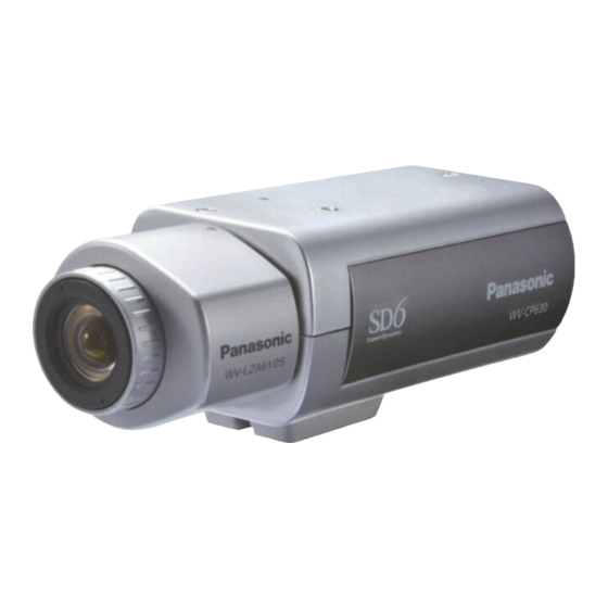
Color CCTV Camera
WV-CP630/G
Model No.
WV-CP634E
(Lens is optional for WV-CP630 Series.)
Before attempting to connect or operate this product,
please read these instructions carefully and save this manual for future use.
The model number is abbreviated in some descriptions in this manual.
Advertisement
Table of Contents

Related Manuals for Panasonic WV-CP630/G


Summary of Contents for Panasonic WV-CP630/G
- Page 1 Operating Instructions Color CCTV Camera WV-CP630/G Model No. WV-CP634E (Lens is optional for WV-CP630 Series.) Before attempting to connect or operate this product, please read these instructions carefully and save this manual for future use. The model number is abbreviated in some descriptions in this manual.
-
Page 2: Preface
Preface About the user manuals The operating instructions of the camera consist of 2 sets: these operating instructions (PDF) and Installation Guide. This document explains how to configure the settings of the camera. Refer to the installation guide for further information about how to install the camera. ®... -
Page 3: Table Of Contents
Contents Preface................... 2 Configure.the.alarm.input.terminal.setting....18 About.the.user.manuals............. 2 Configure.the.alarm.output.terminal.setting....19 12..Privacy.zone.setting.[PRIVACY.ZONE]..... 19 Trademarks.and.registered.trademarks......2 Contents................. 3 13..Image.stabilizer.setting.[STABILIZER]....... 20 About.the.setup.menus............4 14..Electronic.zoom.setting.[EL-ZOOM]......20 List.of.setup.menu.............. 4 15..Upside-down.setting.[UPSIDE-DOWN]..... 21 Basic.operation..............5 16..Lens.distortion.correction.[LDC]......... 21 Screen.transition.diagram ..........6 Back.focus.setting.[BACK-FOCUS.SETUP]. -
Page 4: About.the.setup.menus
About the setup menus Performing each setting item in the setup menu should be completed in advance to use this unit. Perform the settings for each item in accordance with the conditions of the camera shooting area. List of setup menu Setup item Description CAMERA ID... -
Page 5: Basic.operation
The operations in the setup menu are performed with the operation buttons after calling up the setup menu on the connected video monitor. The description below explains how to operate the setup menu basically. Screenshots of WV-CP630/G are shown as an example. Screenshot 1 Hold down the [SET] button for about 2 seconds to call up the Step 1 top screen of the setup menu. -
Page 6: Screen.transition.diagram
Screen transition diagram Top screen “CAMERA ID” screen MODEL WV-CP630 SERIES **CAMERA ID** CAMERA ID 0123456789 CAMERA ABCDEFGHIJKLM SYSTEM NOPQRSTUVWXYZ BACK-FOCUS ().,'":;&#!?= SPECIAL +-*/%$ LANGUAGE SPACE POSI RET TOP END RESET ....SETUP DISABLE “CAMERA SETUP” screen **CAMERA SETUP** SCENE1 ALC/ELC SHUTTER ON(HIGH) -
Page 7: Camera.title.setting.[Camera.id]
Camera title setting [CAMERA ID] This item specified the camera title. The camera title that indicates the camera location and other information about the camera is created with alphanumerics and symbols, and is displayed on the screen. The camera title is named with up to 16 characters. Follow the procedure below to specify the camera title. -
Page 8: Camera.operation.setting.[Camera.setup]
Camera operation setting [CAMERA SETUP] The following describes the camera operation settings. The following settings can be configured on the “CAMERA SETUP” screen displayed from the top screen. Refer to page 5 for how to call up the screen. The settings configured on the “CAMERA SETUP” screen will be saved as a scene file. 1. -
Page 9: About.super.dynamic.6.Functions
About Super Dynamic 6 Functions Subject in the dark Subject in the bright area is hard to notice. area is hard to notice. If there is high contrast between the bright and dark areas in a shooting zone, the dark area becomes less visible because the camera adjusts the iris in accordance with the bright area. -
Page 10: About.the.highlight.compensation.(Hlc).Function
Step 3 When the SUPER-D6 function is set to "OFF", bright areas of an image are masked to facilitate the visibility of dark areas. Move the cursor to “MASK SET” and press the [SET] button. → The mask setting screen appears. Step 4 Press the [UP], [DOWN], [RIGHT] and [LEFT] buttons to move the flashing cursor to the area to be masked and press the [SET] button. -
Page 11: About.the.fog.compensation.function
About the fog compensation function This function enables the camera to obtain clear images in hazy weather. When “SUPER-D6” or “HLC” is set to “ON”, this function is not available. Adjust the amplitude of fog compensation. When the cursor moves towards the “+” direction, the fog compensation level increases; when the cursor moves towards the “-”... -
Page 12: White.balance.setting.[White.bal]
Note: • When “ALC/ELC” is set to “ELC” or “ALC+”, only the AUTO mode is enabled. • When “SHUTTER” is set to options other than “OFF”, the electronic sensitivity enhancement setting cannot be performed and “---” appears. • When the magnification of “SENS UP” is increased, the screen becomes coarser, more whitish, or more flawed. However, this phenomenon is normal. -
Page 13: Manual.fine.adjustment.of.white.balance
Manual fine adjustment of white balance The white balance is manually fine adjusted after white balance automatically adjustment in the automatic color temperature tracking mode (ATW1, ATW2) or automatic white balance control mode (AWC). Follow the procedures below. “CAMERA SETUP” screen Fine adjustment screen Area setting screen **CAMERA SETUP**... -
Page 14: Black-And-White.mode.setting.[D&N.(Ir).]
8. Black-and-white mode setting [D&N (IR) ] The settings relating to the black-and-white mode can be configured. Follow the procedure below “D&N (IR)” screen “CAMERA SETUP” screen **CAMERA SETUP** **D&N(IR) **(1) SCENE1 AUTO1 ALC/ELC SHUTTER LEVEL HIGH . I .. ON(HIGH) DURATION TIME SENS UP... -
Page 15: Vmd.setting.[Vmd]
Step 5 Move the cursor to “BURST (BW)”, and decide whether or not to provide a burst signal output in the black-and-white mode. ON (default): Provides a burst signal output. OFF: Does not provide any burst signal output. Note: • Images may not be displayed appropriately without burst signals when camera images are displayed in the black-and-white mode depending on a monitor or VTR model to be used. - Page 16 Step 1 Move the cursor to “MOTION DET” and press the [SET] button. → The “MOTION DET” screen appears. Step 2 Move the cursor to “MASK SET” and press the [SET] button. → The mask setting screen appears. “MOTION DET” screen Mask setting screen ** MOTION DET **(1) ..
-
Page 17: Setting.of.scene.change.detection
Step 7 Move the cursor to “DWELL TIME ” and select the dwell time from the following. (unit: seconds) 2S (default)/5S /10S /30S Alarm signal will be issued once a continuously moving object is detected within the specified time. Setting of scene change detection This function detects a change in the subject state that occurs by covering the camera with a cloth, a cap, or others, or by changing the camera direction largely. -
Page 18: Camera.system.setting.[System.setup]
Camera system setting [SYSTEM SETUP] Performs the settings relating to the camera system such as synchronization, alarm input/output terminal and privacy zone. The following settings can be configured on the “SYSTEM SETUP” screen displayed from the top screen. Refer to page 5 for how to call up the screen. “SYSTEM SETUP”... -
Page 19: Configure.the.alarm.output.terminal.setting
Configure the alarm output terminal setting Select the operation of the alarm output terminal. Follow the procedure below. “SYSTEM SETUP” screen “ALARM IN/OUT” screen **SYSTEM SETUP** **ALARM IN/OUT** SYNC ALARM IN ALARM IN/OUT ALARM OUT PRIVACY ZONE STABILIZER EL-ZOOM UPSIDE-DOWN I.. -
Page 20: Image.stabilizer.setting.[Stabilizer]
Step 3 Move the cursor to “POSITION” and press the [SET] button. Step 4 Press the [UP], [DOWN], [RIGHT] and [LEFT] buttons to determine the left upper position of the zone to be set and press the [SET] button. Step 5 Press the [UP], [DOWN], [RIGHT] and [LEFT] buttons to determine the lower right position of the zone to be set and press the [SET] button. -
Page 21: Upside-Down.setting.[Upside-Down]
Step 1 Move the cursor to “EL-ZOOM” and select “ON” and press the [SET] button. → The “EL-ZOOM” screen appears. Step 2 Move the cursor to “→ PUSH SET” of “ZOOM” and press the [SET] button. → The zoom setting screen appears. Step 3 Adjust the angular field of view by changing the electronic zoom factor (up to 2x) using the [UP] or [DOWN] button, and press the [SET] button. -
Page 22: Back.focus.setting.[Back-Focus.setup]
Back focus setting [BACK-FOCUS SETUP] Back focus setting [BACK-FOCUS SETUP] Selects the back focus setting type and performs fine adjustment. The following setting can be configured on the “BACK-FOCUS SETUP” screen displayed from the top screen. Refer to page 5 for how to call up the screen. The lens adjustment ( Installation Guide) shall be performed before the back focus adjustment. - Page 23 Step 3 Move the cursor to “C/L ← → B/W” and select the back focus adjustment type from the following: AUTO (default): Adjusts the back focus function automatically and corrects out of focus when switching between color and black- and-white images. PRESET: Performs the preset movement to each specified back focus position when switching between color and black-and-white images.
-
Page 24: Special.menu.setting.[Special.setup]
Special menu setting [SPECIAL SETUP] The special menu setup is performed including the setting of the camera image quality and the communication configuration when a receiver is used. The following settings are to be configured on the “SPECIAL SETUP” screen displayed from the top screen. Refer to page 5 for how to call up the screen. -
Page 25: Pixel.compensation.[Pix.off]
21. Pixel compensation [PIX OFF] Flaws of pixel in the displayed camera image are corrected. Up to 16 points can be corrected. Follow the procedure below. "SPECIAL SETUP" screen “PIX OFF” screen Pixel compensation positioning screen **SPECIAL SETUP** ** PIX OFF ** ..I..160 CHROMA GAIN ..I.. -
Page 26: Camera.language.selection.[Language.setup]
Camera language selection [LANGUAGE SETUP] A language for the setup menu is selected from the following: The language selection can be made on the “LANGUAGE SETUP” screen displayed from the top screen. Refer to page 5 for how to call up the screen. “LANGUAGE SETUP”... -
Page 27: Shortcut.operation
Shortcut operation Use of a system controller with the “Camera function” button allows users to perform the shortcut settings with use of the numeric keypad and camera function button. The available shortcut operations with this unit are shown as follows. System controller operation Setting contents [9] + [0] + [Camera function]... - Page 28 Panasonic Marketing Europe GmbH Panasonic Marketing Europe GmbH Winsbergring 15, 22525 Hamburg F.R.Germany Winsbergring 15, 22525 Hamburg, Germany © Panasonic System Networks Co., Ltd. 2011 © Panasonic System Networks Co., Ltd. 2011 © Panasonic System Networks Co., Ltd. 2014 sL1014-0 PGQP1856ZA ©...