Table of Contents
Advertisement
Quick Links
Installation and Service Instructions
LoganoUS/CA GC 144 II
Read carefully prior to installation and maintenance.
Gas boiler
WARNING!
Installation, adjustment, modification, opera-
tion or maintenance of the heating system
carried out by unqualified personnel may
result in property damage, personal injury,
and loss of life.
The directions of this installation and main-
tenance manual must be followed precisely.
Contact a qualified service company, service
provider or the gas company if support or
additional information is required.
CAUTION!
Before placing this boiler in operation
observe the safety instructions of this installa-
tion and maintenance manual.
CAUTION!
The operating manual is a component of the
technical documentation handed over to the
operator of the heating system. Discuss the
instructions in this manual with the owner or
operator of the heating system and ensure
that they are familiar with all information
required for operation of the heating system.
Keep this installation and maintenance
manual available for future reference.
Advertisement
Table of Contents

Related Manuals for Buderus Logano US GC 144 II


Summary of Contents for Buderus Logano US GC 144 II
- Page 1 Gas boiler WARNING! Installation, adjustment, modification, opera- tion or maintenance of the heating system carried out by unqualified personnel may result in property damage, personal injury, and loss of life. The directions of this installation and main- tenance manual must be followed precisely. Contact a qualified service company, service provider or the gas company if support or additional information is required.
-
Page 2: Table Of Contents
Contents Contents Safety considerations ....... . . 3 13 Start-up protocol ........19 Key to symbols . -
Page 3: Safety Considerations
▶ Immediately correct all faults to prevent system damage. ▶ No open flame! No smoking! Do not use lighters ▶ Only use original Buderus spare parts. Losses caused by the use of ▶ Prevent spark formation. Do not operate electrical switches, parts not supplied by Buderus are excluded from the Buderus including telephones, plugs or door bells. -
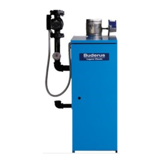
Page 4: Product Description
Product Description Boiler Operating Conditions Product Description The hot water piping system must comply with the current legislation and local regulations. If an existing boiler is replaced, the complete hot The boiler is a low temperature gas boiler. water piping system must be inspected to ensure that it is in perfect The boiler consists of the following main components: condition to ensure safe operation. -
Page 5: Dimensions And Connections
Dimensions and Connections Dimensions and Connections VK 1¼" GAS ½" (GAS ½")* EL ¾" RK 1¼" 6 720 804 440-02.1T Fig. 2 Back, side and front view, measurements in inches * optional connection Boiler supply Boiler return Boiler drain GAS Gas connection Dimensions Vent Min. -
Page 6: Scope Of Delivery
Scope of delivery ▶ Remove screws that secure the boiler base to the wood pallet. Scope of delivery ▶ Pick up boiler base from one side and slide to the edge of the pallet. Place a steel pipe as roller under the boiler base. Place additional ▶... -
Page 7: Lifting And Carrying The Boiler
Placing the boiler ▶ Place the boiler at its final postion. Lifting and carrying the boiler The boiler can be picked up at the both long sides of the boiler as shown. CAUTION: Risk of injury due to carrying heavy loads. ▶... -
Page 8: Connecting The Heating System
Boiler installation Connecting the heating system NOTICE: Boiler damage due to moisture. ▶ Protect the components of the gas ignition system from moisture (dripping, spray, rain) during installation of the boiler, during operation and during maintenance work (such as replacing the pump, replacing the control, etc.). -
Page 9: Electrical Connections
Boiler installation Installation of B-kit We recommend installing a y-strainer (accessory) in the The relief valve and the pressure/temperature gauge are mounted on the boiler return connection to reduce built-up of debris on boiler supply manifold which is attached to the VK (supply) connection the water side inside the boiler. -
Page 10: Fuel Gas Supply Connection
Boiler installation Description of field installed wiring connections using factory supplied junction box. ▶ Remove two knock-outs from the left side of boiler panel to route electrical feed and pump power into junction box. ▶ Route electrical power from the outside into junction box. ▶... -
Page 11: Installation At High Altitudes
(based on supplied relief 45 psi external thread of the pipe connections. valve) If you wish to convert the boiler to propane, please contact Buderus for 58 psi (with special relief valve) 75 psi the required conversion components. Do not attempt to convert the... -
Page 12: Check Openings For Combustion Air Supply And Venting
Check openings for combustion air supply and venting ▶ Open fill valve for additional filling. Check openings for combustion air supply ▶ Set static system pressure to at least 15 psi at indicated on pressure relief valve ( figure 15). and venting ▶... -
Page 13: Requirements For Connection To Chimneys Or Venting Systems
Requirements for connection to chimneys or venting systems (crawl space or attic). The shortest dimension of all inlet and outlet ▶ If necessary, close all doors and windows in the building and all doors openings must not be less than three inches. between the space in which the heating systems that remain connected to the venting system are installed and the other rooms of ▶... -
Page 14: Placing The Heating System In Operation
Placing the heating system in operation fastened to prevent it from hanging. A support must be installed at least ▶ Connect vent damper plug into the terminal bar as shown in the every five feet. Fasten every connection with at least three (3) corrosion- circuit diagram. -
Page 15: Starting Up The Gc 144 Ii
Placing the heating system in operation ▶ Check all combustion air and all flue gas ducts and openings. ( WARNING: Danger of explosion if you smell gas there is chapter 8, page 12 and chapter 9, page 13). danger of explosion! Verifying the appliance ▶... -
Page 16: 11.1.2 Turning On Heating System
(set temperature dial at least 10°F above ambient). ▶ If you are unable to turn the knob by hand, do not try to repair it. ▶ Call Buderus technical service for assistance. ▶ Turn ON/OFF knob ( figure 23) counterclockwise to the ON position. - Page 17 Final start-up procedures Natural Gas GC 144 II [inch W.C.] [inch W.C.] Table 10 Orifice pressure at 60°F / 30" Hg. These values are only valid in the U.S.A. and only for elevations from 0-8500ft. 6 720 804 440-25.1T Fig. 25 Main burner Main burner flame Checking flame rod ▶...
- Page 18 Final start-up procedures ▶ Turn gas valve ON/OFF knob clockwise to OFF position. Checking aquastat ▶ Close main gas shut-off. Check the function of the maximum aquastat to make sure that it switches the boiler off as soon as the boiler water temperature set at the ▶...
-
Page 19: Start-Up Protocol
Start-up protocol Start-up protocol Please check off all startup steps and record measurements in the appropriate tables. Start-up procedure Remarks or measured values Type of gas Natural gas Has the leak test been completed? Check combustion air, inlet and outlet openings and flue gas connection Check the equipment (correct orifices? See below) and convert gas type if necessary... -
Page 20: Taking The Heating System Out Of Operation
When replacing components use only parts approved by ▶ Leave the heating system switched ON constantly as Buderus. Maintenance is required once a year. Record the results of the much as possible. inspection in the protocol on page 25. -
Page 21: Cleaning The Boiler
Boiler inspection and maintenance 6 720 804 440-40.1T Fig. 32 Correct ignition flame setting 6 720 804 440-38.1T Flame rises ½" to 1-½" above sensor Fig. 30 Gas valve Ignition flame ON/OFF knob (shown in ON position) ▶ Remove the safety screw on the adjustment screw for the igniter (... -
Page 22: 15.5.1 Cleaning The Boiler With Brushes
Boiler inspection and maintenance 15.5.1 Cleaning the boiler with brushes Burner removal WARNING: Risk to life from electric shock. ▶ Before opening a unit: disconnect electrical power and lock to prevent accidental reactivation. ▶ If cables are connected incorrectly the system may not operate correctly with possibly dangerous consequences. -
Page 23: Wet Cleaning (Chemical Cleaning)
Boiler inspection and maintenance 15.5.2 Wet cleaning (chemical cleaning) For wet cleaning use a suitable cleaning agent depending on the degree of build-up of dirt (soot or scale). Use the same procedure as described for cleaning with brushes ( chapter 15.5.1, page 22). Observe the directions for use of the cleaning agent. - Page 24 Boiler inspection and maintenance ▶ Rinse out burner rods with a water jet; hold burner so water enters all ▶ Follow instructions in „Final start-up procedures“. slots of the burner rods and drains back out. ▶ Test low water alarm. ▶...
-
Page 25: Maintenance Protocol
Boiler inspection and maintenance 15.7 Maintenance protocol Please check off the maintenance work as it is completed and record the measured values. Follow the instructions on the following pages. Maintenance work Page Date: Date: Inspection of the flue system including combustion page 20 air, inlet and outlet openings Gas manifold pressure... - Page 26 Boiler inspection and maintenance Date: Date: Date: Date: Date: –––––––inches W. C. –––––––inches W. C. –––––––inches W. C. –––––––inches W. C. –––––––inches W. C. –––––––inches W. C. –––––––inches W. C. –––––––inches W. C. –––––––inches W. C. –––––––inches W. C. Table 13 Maintenance protocol Logano GC 144 II –...
-
Page 27: Troubleshooting The Gc 144 Ii
Boiler inspection and maintenance 15.8 Troubleshooting the GC 144 II Equipment required: Wiring diagrams ( chapter 17, page 30) and voltage detectors for 120 VAC and 24 VAC. Start Close gas valve. Set thermostat • Check electrical power source, low-voltage transformer, thermostat (con- (control) to require heat (vent trol) and wiring. - Page 28 Boiler inspection and maintenance Room thermostat (control) signals heat requirement START Vent damper (if installed) opens. PHASE 1 Ignition spark generator operates • ignition gas valve opens. Ignition attempt Ignition burner operation Ignition flame burns, automatic ignition flame does not burn, ignition signals steady ignition pilot assembly starts ignition at- flame.
-
Page 29: Technical Specifications
If the installation is over 8500 feet above see level, please contact Buderus for another product option as the GC 144 II is not approved above 8500 feet operation.Do not attempt to alter this boiler without consulting Buderus. -
Page 30: Electrical Circuit Diagrams
Electrical circuit diagrams Electrical circuit diagrams 6 720 804 440-71.1TT Fig. 43 Wiring Diagram– GC 144 II Logano GC 144 II – 6 720 808 893 (2017/02) - Page 31 Electrical circuit diagrams 6 720 804 440-72.1TT Fig. 44 Wiring Diagram– GC 144 II Logano GC 144 II – 6 720 808 893 (2017/02)