Table of Contents
Advertisement
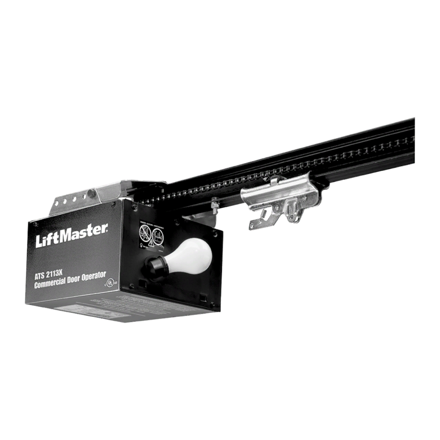
COMMERCIAL DOOR OPENER
Model ATS 2113X 1/2 HP
For Residential And Light Duty Commercial Use
Install on Sectional Doors Only
Owner's Manual
■
Please read this manual and the enclosed safety materials carefully!
■
Fasten the manual near the garage door after installation.
■
The door WILL NOT CLOSE unless the Protector System
properly aligned.
■
Periodic checks of the opener are required to ensure safe operation.
■
The model number label is located on the front panel of your opener.
■
DO NOT exceed 8 complete cycles of door operation per hour.
®
The Chamberlain Group, Inc.
845 Larch Avenue
Elmhurst, Illinois 60126-1196
www.liftmaster.com
®
is connected and
Advertisement
Table of Contents

Related Manuals for Chamberlain LiftMaster ATS 2113X


Summary of Contents for Chamberlain LiftMaster ATS 2113X
- Page 1 COMMERCIAL DOOR OPENER Model ATS 2113X 1/2 HP For Residential And Light Duty Commercial Use Install on Sectional Doors Only Owner’s Manual ■ Please read this manual and the enclosed safety materials carefully! ■ Fasten the manual near the garage door after installation.
-
Page 2: Table Of Contents
Operation safety instructions ......23 Using your garage door opener ......23 Using the wall-mounted door control . -
Page 3: Preparing Your Garage Door
To prevent damage to garage door and opener: • ALWAYS opener. • ONLY operate garage door opener at 120V, 60 Hz to avoid malfunction and damage. Tools needed During assembly, installation and adjustment of the opener, instructions will call for hand tools as illustrated below. Pencil... -
Page 4: Planning
Planning Identify the type and height of your garage door. Survey your garage area to see if any of the conditions below apply to your installation. Additional materials may be required. You may find it helpful to refer back to this page and the accompanying illustrations as you proceed with the installation of your opener. -
Page 5: Carton Inventory
Carton Inventory Your garage door opener is packaged in two cartons which contain the motor unit and all parts illustrated below. Accessories will depend on the model purchased. If anything is missing, carefully Mounting Hardware Rail Support (Rail Support Bracket) Bracket "C"... -
Page 6: Attach The Rail To The Motor Unit
TYPE AND SIZE BOLT Rail Chain Opener To avoid possible SERIOUS INJURY to fingers from moving garage door opener: • ALWAYS keep hand clear of sprocket while operating opener. • Securely attach rail support bracket BEFORE operating. Hex bolts with Lock Washers 1/4"-20x5/8"... -
Page 7: Tighten The Chain
Disable ALL locks and remove ALL ropes connected to garage door BEFORE installing opener to avoid entanglement. Install garage door opener 7 feet (2.13 m) or more above floor. Mount emergency release handle 6 feet (1.83 m) above floor. NEVER connect garage door opener to power source until instructed to do so. -
Page 8: Determine The Header Bracket Location
INSTALLATION STEP 1 Determine the Header Bracket Location To prevent possible SERIOUS INJURY or DEATH: • Header bracket MUST be RIGIDLY fastened to structural support on header wall or ceiling, otherwise garage door might not reverse when required. DO NOT install header bracket over drywall. -
Page 9: Install The Header Bracket
INSTALLATION STEP 2 Install the Header Bracket You can attach the header bracket either to the wall above the garage door, or to the ceiling. Follow the instructions which will work best for your particular requirements. DO NOT install the header bracket over drywall. -
Page 10: Attach The Rail To The Header Bracket
Header Wall Header Bracket Chain Pulley Bracket Rail Garage Door HARDWARE SHOWN ACTUAL SIZE Clevis Pin 5/16"x2-3/4" INSTALLATION STEP 3 Attach the Rail to the Header Bracket • Position the opener on the garage floor below the header bracket. Use packing material as a protective base. NOTE: If the door spring is in the way you’ll need help. -
Page 11: Position The Opener
Lag Screw 5/16"-18x1-7/8" Hex Bolt 5/16"-18x7/8" Nut 5/16"-18 To prevent damage to garage door, rest garage door opener rail on 2x4 placed on top section of door. • If the top section or panel hits the trolley when you raise the door, pull down on the trolley release arm to disconnect inner and outer sections. -
Page 12: Install The Door Control
INSTALLATION STEP 6 Install the Door Control Locate the door control within sight of the door at a minimum height of 5 feet (1.5 m) where small children cannot reach, and away from all moving parts of the door and door hardware. Strip 7/16"... -
Page 13: Install The Light
Then the light will turn OFF. • If the bulb burns out prematurely due to vibration, replace with a “Garage Door Opener” bulb. NOTE: Use only standard light bulbs. The use of short neck or specialty light bulbs may overheat the endpanel or light socket. -
Page 14: Electrical Requirements
To avoid installation difficulties, do not run the opener at this time. To reduce the risk of electric shock, your garage door opener has a grounding type plug with a third grounding pin. This plug will only fit into a grounding type outlet. If the plug doesn't fit into the outlet you have, contact a qualified electrician to install the proper outlet. -
Page 15: Install The Protector System
INSTALLATION STEP 10 ® Install The Protector System The safety reversing sensor must be connected and aligned correctly before the garage door opener will move in the down direction. IMPORTANT INFORMATION ABOUT THE SAFETY REVERSING SENSOR When properly connected and aligned, the sensor will detect an obstacle in the path of its electronic beam. - Page 16 INSTALLING THE BRACKETS Figure 1, 2 and 3 show recommended assembly of bracket(s) and “C” wrap based on the wall installation of the sensors on each side of the garage door as shown on page 15, or on the garage door tracks themselves.
- Page 17 MOUNTING AND WIRING THE SAFETY SENSORS • Center each sensor unit in a “C” wrap with lenses pointing toward each other across the door (see Figure 6). • Secure sensors with the hardware shown. Finger tighten the wing nut on the receiving eye to allow for final adjustment. Securely tighten the sending eye wing nut.
-
Page 18: Fasten The Door Bracket
INSTALLATION STEP 11 Fasten the Door Bracket A horizontal brace should be long enough to be secured to 2 vertical supports. A vertical brace should cover the height of the top panel. The illustration shows one piece of angle iron as the horizontal brace. -
Page 19: Connect The Door Arm To The Trolley
INSTALLATION STEP 12 Connect Door Arm to Trolley SECTIONAL DOORS ONLY • Make sure garage door is fully closed. Pull the emergency release handle to disconnect the outer trolley from the inner trolley. Slide the outer trolley back (away from the door) about 2"... -
Page 20: Adjust The Travel Limits
ADJUSTMENT STEP 1 Adjust the UP and DOWN Travel Limits Limit adjustment settings regulate the points at which the door will stop when moving up or down. To operate the opener, press the Door Control push bar. Run the opener through a complete travel cycle. •... -
Page 21: Adjustment
ADJUSTMENT STEP 2 Adjust the Force Force adjustment controls are located on the back panel of the motor unit. Force adjustment settings regulate the amount of power required to open and close the door. If the forces are set too light, door travel may be interrupted by nuisance reversals in the down direction and stops in the up direction. -
Page 22: Test The Safety Reversal System
(2.5 cm), and the opener lights will flash. The garage door opener will not close from a remote if the indicator light in either sensor is off (alerting you to the fact that the sensor is misaligned or obstructed). -
Page 23: Operation
Hold the push button or bar down until the door starts to move. • The Keyless Entry (See Accessories): garage door opener, it must be programmed before use. See Programming. When the opener is activated (with the safety reversing sensor correctly installed and aligned) If open, the door will close. -
Page 24: Using The Wall-Mounted Door Control
Using the Wall-Mounted Door Control Press the push button to open or close the door. Press again to reverse the door during the closing cycle or to stop the door while it’s opening. To Open the Door Manually To prevent possible SERIOUS INJURY or DEATH from a falling garage door: •... -
Page 25: Having A Problem
The opener lights don’t turn on: • Replace the light bulbs (75 watts maximum). Use a standard neck garage door opener bulb if regular bulb burns out. The opener lights don’t turn off: • Is the Light feature on? Turn it off. -
Page 26: Programming
The owner of the copyright in the garage door opener does not authorize the purchaser or supplier of the non-rolling code transmitter to circumvent that technical measure. -
Page 27: To Add Or Change A Keyless Entry Pin (Optional)
To Add or Change a Keyless Entry PIN (Optional) NOTE: Your new Keyless Entry must be programmed to operate your garage door opener. USING THE “LEARN” BUTTON Press and release the “learn” button on motor unit. The learn indicator light will glow steadily for 30 seconds. -
Page 28: Multi-Function Door Control (Optional)
Multi-Function Door Control (Optional) INSTALLATION Locate door control within sight of the door at a minimum height of 5 feet (1.5 m) where small children cannot reach, and away from moving parts of the door and door hardware. If installing into drywall, drill 5/32"... -
Page 29: Repair Parts
REPAIR PARTS Rail Assembly Parts Installation Parts PART 41A4166 41B4494-1 41A2828 12B374 12B380 41A4353 41A4373A 178B35 12B483 178B34 178B73 12B484 12B485 41A2770 41A4116 114A3155 114A3155SP PART DESCRIPTION 4A1008 Master link kit 41A2780 Chain pulley bracket 41A3489 Complete trolley assembly CD1008 8 Foot (2.44 m) Rail Assy. -
Page 30: Motor Unit Assembly Parts
Motor Unit Assembly Parts (Down) LIMIT SWITCH ASSY. Contact Brown Wire Drive Gear Center Limit (Up) Contact Contact PART DESCRIPTION 41C5069 Rail support bracket assembly kit 41B4569 Pulley (Chain) 41A5668 Gear and sprocket assembly. Complete with: Spring washer, thrust washer, retaining washer, bearing plate roll pins (2), drive gear and worm gear, helical gear w/retainer and grease,sprocket shaft plate... -
Page 31: Accessories
Control with SECURITY✚ With key ring and fastening strip. 78LM Multi-Function Door Control Panel: Provides a Lock Feature which prevents operation of garage door opener from portable remotes and a Light Feature for constant light. ® 376LM SECURITY✚ Keyless Entry:... -
Page 32: Repair Parts And Service
The Chamberlain Group, Inc. (“Seller”) warrants to the first retail purchaser of this product, for the residence in which this product is originally installed, that it is free from defect in materials and/or workmanship for a period of one year from the date of purchase [and that the motor is free from defect in materials and/or workmanship for the lifetime of the product].