Chamberlain T Installation Manual
Commersial door operator
Hide thumbs
Also See for T:
- Installation manual (37 pages) ,
- User manual (29 pages) ,
- Owner's manual (28 pages)
Table of Contents
Advertisement
Available languages
Available languages
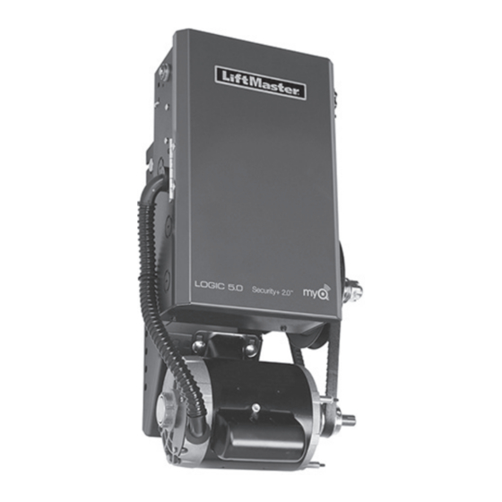
Logic 5.0 Commercial Door Operator
NOT FOR RESIDENTIAL USE
• Please read this manual and the enclosed safety materials completely, prior to installation
and use!
• This Product Is To Be Installed And Serviced By A Trained Door Systems Technician Only.
• A LiftMaster Monitored Entrapment Protection (LMEP) Device is REQUIRED for B2, T, TS,
and FSTS wiring types.
• Upon completion of installation, test entrapment protection device(s) prior to placing the
operator into active use.
• These operators are compatible with myQ
2 YEAR WARRANTY
Serial #
Installation Date
LiftMaster
300 Windsor Drive
Oak Brook, IL 60523
INSTALLATION MANUAL
®
Models T, APT, H, J, HJ, GH, and GT
and Security+ 2.0
accessories.
®
®
Advertisement
Chapters
Table of Contents
Troubleshooting

Related Manuals for Chamberlain T


Summary of Contents for Chamberlain T
- Page 1 • This Product Is To Be Installed And Serviced By A Trained Door Systems Technician Only. • A LiftMaster Monitored Entrapment Protection (LMEP) Device is REQUIRED for B2, T, TS, and FSTS wiring types. • Upon completion of installation, test entrapment protection device(s) prior to placing the operator into active use.
-
Page 2: Table Of Contents
Emergency Disconnect System Model GT and T ... . 25 Install the Chain (Models T and GT) ....8 Emergency Disconnect System Model APT . -
Page 3: Safety Information
SAFETY INFORMATION IMPORTANT NOTES: • BEFORE attempting to install, operate or maintain the commercial door operator, you must read and fully understand Mechanical this manual and follow all safety instructions. • DO NOT attempt repair or service of a commercial door operator unless you are an Authorized Service Technician. -
Page 4: Trolley Operators
#41 chain; #48 output chain on trolley. MODEL VOLTAGE PHASE Model T First-stage heavy-duty 5L V-belt; second #41 chain; #48 (for 1/3 and 1/2HP) and #41 (for 3/4 and 1HP) output chain on trolley. Model GT 10:1 fi rst-stage using heavy-duty gears running •... - Page 5 OPERATOR SPECIFICATIONS MAXIMUM DOOR AREA (SQ. FT.) MODEL T MODEL APT 24 ga. 24 ga. 20 ga. 16 ga. 20 ga. 16 ga. 22 ga. 22 ga. Steel Steel Steel Steel Steel Steel Fiberglass Alum. Wood Alum. Wood Doors Doors...
- Page 6 - For operators manufactured before February of 2018 with a caliper brake, add 3-1/2" (8.9 cm) (Standard on APT, T 3/4 and T 1 HP models; Optional on 1/2 HP, not available on 1/3 HP models.) For operators manufactured after January of 2018 with a drum brake, add 5" (12.7 cm) MODEL GT Hanging Weight: 140 lbs.
-
Page 7: Assembly
ASSEMBLY ASSEMBLE THE OPERATOR (MODELS T AND GT) NOTE: For Model APT assembly refer to page 9. Install the track spacers evenly over the length of the track. HARDWARE Fasten the spacers to the track with bolt (A) and fl ange hex nuts (B). -
Page 8: Install The Chain (Models T And Gt)
INSTALL THE CHAIN (MODELS T AND GT) Position the trolley 2 inches (5.1 cm) away from the front idler. Attach the chain to the trolley threaded shaft using the master link. Run the chain along the track to the operator. Wrap the chain around the operator drive sprocket. -
Page 9: Assemble The Operator (Model Apt)
ASSEMBLE THE OPERATOR (MODEL APT) Install the track spacers evenly over the length of the track. HARDWARE Fasten the spacers to the track with bolt (A) and fl ange hex nuts (B). Flange Hex Nut Install the front idler in the second set of holes on the end of Bolt 3/8"-16 x 3/4"... -
Page 10: Typical Installation
TYPICAL INSTALLATION INSTALL THE HEADER BRACKET The trolley operator is generally mounted over the center of the To prevent possible SERIOUS INJURY or DEATH: door. However, off center mounting may be required due to interfering structures or location of the door stile / top section •... -
Page 11: Attach The Track To The Header Bracket
ATTACH THE TRACK TO THE HEADER BRACKET AND HANG THE OPERATOR Align the track with the header bracket. To avoid possible SERIOUS INJURY from a falling operator: Insert the clevis pin through the track and header bracket holes. Secure with the fasteners. •... -
Page 12: Attach The Door Arm
ATTACH THE DOOR ARM AND BRACKET Latch the door arm to the trolley. Make sure the open side of HARDWARE the notch on the door arm faces the door. Position the door bracket to the center line of the door and attach the door bracket to the door using appropriate hardware Flanged Hex Nut 3/8"-16 (2) Nylok Nut 3/8"-16 (1) -
Page 13: Hoist And Jackshaft Operators Carton Inventory
Station Open/Close/Stop w/LED BEARINGS: Models H and HJ - Industrial ball bearings on WIRING TYPE: C2 (Factory default), B2, T, TS, D1, E2 and output shaft, heavy-duty oil-fi lled bushing on FSTS. See page 28 for more information reduction shafts. - Page 14 MAXIMUM DOOR AREA (SQ. FT.) MODELS J, H, AND HJ MODEL GH 16 ga. 24 ga. 22 ga. 20 ga. 24 ga. 22 ga. 20 ga. 16 ga. Steel Steel Steel 18 ga. Steel Steel 18 ga. Steel Steel Steel Alum.
- Page 15 WEIGHTS AND DIMENSIONS MODELS J, H AND HJ Hanging Weight: 80-110 lbs. Door Height Plus 4 feet (minimum) 14.5" A - Wall Mounting (36.83 cm) B - Bracket Mounting (rolling door) 16.16" (41.04 cm) 7.25" 3/8" Bolt (18.41 cm) 4.63" (11.76 cm) 7.5"...
-
Page 16: Assembly
ASSEMBLY ASSEMBLE THE OPERATOR The wall or mounting surface MUST provide adequate support for the operator. To prevent possible SERIOUS INJURY or DEATH: • DO NOT connect electric power until instructed to do so. The surface must: • If the door lock needs to remain functional, install an interlock a. -
Page 17: Mounting
MOUNTING Place the door sprocket on the door shaft. Wrap the drive chain around the door sprocket and the drive sprocket then secure with the master link. Align the door and the drive sprockets. Insert keys and fasten the sprockets with the set screws (recommended torque for the set screws is 34-45 in/lb). -
Page 18: Wiring
WIRING To reduce the risk of SEVERE INJURY or DEATH: • ANY maintenance to the operator or in the area near the • ALL electrical connections MUST be made by a qualified operator MUST NOT be performed until disconnecting the individual. -
Page 19: Control Station
CONTROL STATION To prevent possible SERIOUS INJURY or DEATH from the user from coming in contact with the door while operating the controls. electrocution: • Install the entrapment warning placard on the wall next to the • Be sure power is NOT connected BEFORE installing the door control station in a prominent location visible from the door. -
Page 20: Entrapment Protection
• Install the primary monitored photoelectric sensor beam NO HIGHER than 6" (15 cm) above the floor. • This is a required LMEP Device for B2, TS, T, and FSTS wiring types and MUST NOT be disabled. For D1, C2, and E2 wiring the installation of an entrapment protection device is recommended. -
Page 21: Install The Liftmaster Monitored Entrapment Protection (Lmep) Devices (Optional)
INSTALL THE LIFTMASTER MONITORED ENTRAPMENT PROTECTION (LMEP) DEVICES (OPTIONAL) Always refer to the installation instructions included with LiftMaster Entrapment Protection (LMEP) Devices. If a LiftMaster Monitored Entrapment Protection Device is not installed, constant pressure to close will be required from the control station. WIRE THE LIFTMASTER MONITORED ENTRAPMENT PROTECTION (LMEP) DEVICES Connect the LiftMaster Monitored Entrapment Protection... -
Page 22: Adjustment
ADJUSTMENT IMPORTANT SAFETY INSTRUCTIONS TO REDUCE THE RISK OF SEVERE INJURY OR DEATH: 1. READ AND FOLLOW ALL WARNINGS AND INSTRUCTIONS. 8. After ANY adjustments are made, the entrapment protection device(s) MUST be tested. Failure to adjust the operator 2. ALWAYS keep remote controls out of reach of children. properly may cause SEVERE INJURY and DEATH. -
Page 23: Clutch Adjustment (Belt Drive Model Operators)
(clutch must be properly adjusted). In addition, the RPM eliminates the need for a centrifugal switch on single phase motors. Benefi t: The Auxiliary Reversal System reverses the operator upon RPM Sensor hitting an obstruction, preventing excessive door and operator damage. -
Page 24: Testing
1/2HP. Brake can be fi eld-installed for 1/3 and NOTE: The Logic 5.0 logic board will automatically learn the 1/2 HP T, H, J, DJ, HJ and DHJ). LMEP Device once it is properly connected. If the LMEP Device is... -
Page 25: Manual Release
MANUAL RELEASE EMERGENCY DISCONNECT SYSTEM MODELS GT AND T To prevent possible SERIOUS INJURY or DEATH from a falling TO DISCONNECT DOOR FROM OPERATOR door or arm: The door should be in the fully closed position if possible. • DISCONNECT electric power to the operator BEFORE manually operating your door. -
Page 26: Emergency Disconnect System Model H, Gh, J, And Hj
EMERGENCY DISCONNECT SYSTEM MODELS H, GH, J, AND HJ To prevent possible SERIOUS INJURY from a moving chain: • DISCONNECT electric power to the operator BEFORE manually These operators have provisions for manually operating the door operating your door. in case of emergency or power failure. Refer to the appropriate •... -
Page 27: Programming
PROGRAMMING INTRODUCTION TO PROGRAMMING Many programmable functions require that a LiftMaster LOGIC BOARD PUSH BUTTONS (OPEN, CLOSE, STOP) Entrapment Protection (LMEP) Device be installed in order to Open, Close and Stop buttons are mounted directly on the logic function. Refer to the Entrapment Protection section. board. -
Page 28: Determine And Set Wiring Type
DETERMINE AND SET WIRING TYPE Read the descriptions of the different wiring types to determine which setting will be correct for each application. Once the wiring type is determined, set the selector dial accordingly. WIRING TYPE DEVICE ACTION STATE RESPONSE Operator at OPEN limit No change in state Operator at CLOSE limit... - Page 29 DETERMINE AND SET WIRING TYPE (CONTINUED) WIRING TYPE DEVICE ACTION STATE RESPONSE Operator at OPEN limit No change in state Operator at CLOSE limit Door opens to closest OPEN limit or Mid-Stop OPEN button is pressed Door opening No change in state momentarily: Door closing Door will auto reverse to OPEN limit...
- Page 30 DETERMINE AND SET WIRING TYPE (CONTINUED) WIRING TYPE DEVICE ACTION STATE RESPONSE Operator at OPEN limit No change in state Operator at CLOSE limit Door opens to closest OPEN limit or Mid-Stop OPEN button is pressed Door opening No change in state momentarily Door closing No change in state...
- Page 31 DETERMINE AND SET WIRING TYPE (CONTINUED) WIRING TYPE DEVICE ACTION STATE RESPONSE Operator at OPEN limit No change in state Operator at CLOSE limit Door opens to closest OPEN limit or Mid-Stop OPEN button is pressed Door opening No change in state momentarily Door closing Door will auto reverse to OPEN limit...
- Page 32 DETERMINE AND SET WIRING TYPE (CONTINUED) WIRING TYPE DEVICE ACTION STATE RESPONSE Operator at OPEN limit No change in state Operator at CLOSE limit Door opens to closest OPEN limit or Mid-Stop OPEN button is pressed Door opening No change in state momentarily Door closing Door will auto reverse to OPEN limit...
- Page 33 DETERMINE AND SET WIRING TYPE (CONTINUED) WIRING TYPE DEVICE ACTION STATE RESPONSE Operator at OPEN limit No change in state Operator at CLOSE limit Door opens to closest OPEN limit or Mid-Stop OPEN button is pressed Door opening No change in state momentarily Door closing Door will auto reverse to OPEN limit...
- Page 34 DETERMINE AND SET WIRING TYPE (CONTINUED) WIRING TYPE DEVICE ACTION STATE RESPONSE Operator at OPEN limit No change in state Operator at CLOSE limit Door opens to closest OPEN limit or Mid-Stop OPEN button is pressed Door opening No change in state momentarily Door closing Door will auto reverse to OPEN limit...
- Page 35 DETERMINE AND SET WIRING TYPE (CONTINUED) WIRING TYPE DEVICE ACTION STATE RESPONSE Operator at OPEN limit No change in state Operator at CLOSE limit Door opens to the OPEN limit OPEN button is pressed Door opening No change in state momentarily Door closing Door will auto reverse to OPEN limit...
- Page 36 DETERMINE AND SET WIRING TYPE (CONTINUED) WIRING TYPE DEVICE ACTION STATE RESPONSE Operator at OPEN limit No change in state Operator at CLOSE limit Door opens and stops when button is released OPEN button is pressed Door opening No change in state momentarily Door closing No change in state...
-
Page 37: Determine And Set Wiring Type
DETERMINE AND SET WIRING TYPE (CONTINUED) IMPORTANT NOTES: 1. External interlocks may be used with all functional modes. 2. Auxiliary devices are any devices that have only dry contacts. Examples: loop detector, pneumatic or electrical treadles, radio controls, one button stations, pull cords, etc. 3. -
Page 38: Myq Setup
fl ashes rapidly, then release remote control button. The RADIO LED will then remain on solid after releasing the button. Repeat In T and TS modes, operation is OPEN/STOP/CLOSE/REVERSE/ to add additional remote control(s). STOP and Timer-To-Close start/refresh. NOTE: If Car Dealer mode is enabled, SBC will be open only, stopping at the Open 3. - Page 39 PROGRAMMING REMOTE CONTROLS (CONTINUED) Open Close Stop THREE BUTTON REMOTE CONTROL PROGRAMMED FOR REMOTE CONTROL PROGRAMMING FEATURE OPEN/CLOSE/STOP Program Remote Controls from the 3-button control station NOTE: The following programming requires a LiftMaster Monitored (3BCS). Entrapment Protection (LMEP) Device. This feature allows the user to add additional remote controls from Your Security+ 2.0 ®...
-
Page 40: Maintenance Alert System (Mas)
LED will fl ash once for every 5,000 cycle increment programmed Benefi t: The Maintenance Alert System (MAS) assists the installing and the CLOSE button LED will fl ash once for every 3 month dealer in setting up a routine maintenance program. Once increment programmed. -
Page 41: Timer-To-Close
STOP button. The timer will be reactivated on the next operation command. To deactivate the timer for more than one cycle in T mode or in TS mode, attach a defeat switch to 11 and 12 (COMMON and TIMER DEFEAT). -
Page 42: Open Mid-Stop
SBC input and at a minimum one LiftMaster Monitored Entrapment Protection (LMEP) Device installed (refer to page 20). Wiring type must be set to TS or T (located on logic board). Before programing the Car Dealer Mode, both Mid-Stop and Timer-to- Operation will vary Close must be programmed. -
Page 43: Maximum Run Timer (Mrt)
Feature: The operator can learn the time required to open or close a SELECTOR DIAL door plus an additional 10 seconds. Benefi t: If the operator does not meet the open or close contact limit switch within the set time, the operator will stop, limiting potential damage to the door and operator. -
Page 44: Maintenance
MAINTENANCE MAINTENANCE SCHEDULE For use with Maintenance Alert System. Check at the intervals listed in the following chart: To avoid SERIOUS personal INJURY or DEATH: • Disconnect electric power BEFORE performing ANY adjustments or maintenance. • ALL maintenance MUST be performed by a trained door systems technician. -
Page 45: Troubleshooting
BRAKE A drum brake comes standard on T, H, J, and HJ model operators with 3/4HP and larger motors. It comes adjusted from the factory, however, occasional adjustments may be necessary throughout the life of the brake. ADJUSTING DRUM BRAKE: 1. -
Page 46: Troubleshooting Guide
TROUBLESHOOTING GUIDE FAULT POSSIBLE CAUSE A RELAY CLICK IS HEARD WHEN This is normal operation. No action necessary. See Logic Board Overview (page 27) for more GIVEN A COMMAND SLIGHTLY information regarding current sense. BEFORE MOTOR MOVEMENT. RELAY LED'S ON BOARD FLASH IN UNISON WITH THE CLICK. -
Page 47: Troubleshooting Error Codes
TROUBLESHOOTING ERROR CODES Logic 5.0 operators incorporate a self diagnostic feature built into the MAS LED. In addition to indicating when routine maintenance is due, the MAS LED can be used to troubleshoot problems with the operator. If the MAS LED on the logic board or 3-button control station is fl ashing on and off rapidly, the Maintenance Alert System has been triggered and service is due on the operator. -
Page 48: Troubleshooting Radio Functionality
TROUBLESHOOTING RADIO FUNCTIONALITY The error codes will display at the radio LED. ® NOTE: Radio receiver is compatible with SECURITY+ 2.0 remote controls and keyless entry devices. ERROR CODE DISPLAY SYMPTOM POSSIBLE PROBLEM CORRECTION Quick Flash No response from the remote Unlearned remote control - Reprogram the remote control. -
Page 49: Wiring Diagrams
WIRING DIAGRAMS LOGIC (VER. 5.0) 1 PHASE WIRING DIAGRAM Refer to page 21 for LiftMaster Monitored Entrapment Protection (LMEP) Device connections Wiring Diagrams... -
Page 50: Logic (Ver. 5.0) 3 Phase Wiring Diagram
LOGIC (VER. 5.0) 3 PHASE WIRING DIAGRAM - WITH CURRENT SENSING TECHNOLOGY Refer to page 21 for LiftMaster Monitored Entrapment Protection (LMEP) Device connections. Wiring Diagrams... -
Page 51: Accessories
ACCESSORIES ENTRAPMENT PROTECTION DEVICES MONITORED MONITORED CPS-U Dual-Sided Infrared Photo Eyes CPS3CARD Safety Interface Card • NEMA 1 general purpose enclosure. Plug-in Interface card enables use of a second set of monitored photo eyes or edge with a commercial • Dual-sided infrared sensors. door operator. - Page 52 ACCESSORIES myQ ACCESSORIES CONTROL STATIONS 02-101 1-Button Control Station: 828LM LiftMaster ® Internet Gateway Steel enclosure. Enables owners of Commercial Door Operators to open and close their doors and turn on/off lights in or around their facility using a smart phone or tablet computer from anywhere in the world.
-
Page 53: Accessories
ACCESSORIES MOUNTING BRACKETS ADDITIONAL CONTROL ACCESSORIES Heavy gauge steel bracket for vertical or horizontal 10-12360 86LM (15' [4.6 m]) Antenna Extension Kit: mount on either front or top of coil on a rolling door. 86LMT (25' [7.6 m]) The antenna extension kit can be used with EXT-ANT Has a variety of mounting hole patterns compatible for maximum radio receiver range. -
Page 54: Control Connection Diagram
1 BUTTON STATION OR ANY AUXILIARY DEVICE RADIO CONTROLS (WH) (OR) (YE) 11 12 OPEN / CLOSE EXTERNAL B2, T, TS & FSTS RADIO RECEIVER MODE ONLY NOTE: 32 Vdc power supplied from white Keyswitch See note 2. and yellow wires located within the electrical box. - Page 55 • Un dispositif surveillé de protection contre le piégeage avec surveillance LiftMaster (LMEP) est EXIGÉ pour les types de câblage B2, T, TS et FSTS. • Après avoir complété l’installation, tester le ou les dispositifs de protection contre le piégeage avant de placer l’actionneur en service actif.
- Page 56 Système de déconnexion d'urgence Modèles GT et T ..25 Installation de la chaîne (Modèles T et GT) ....8 Système de déconnexion d'urgence Modèle APT .
-
Page 57: Informations De Sécurité
INFORMATIONS DE SÉCURITÉ REMARQUES IMPORTANTES : • AVANT de tenter d’installer, de faire fonctionner ou d’assurer l’entretien de l’actionneur de porte commerciale, il faut lire et Mécanique comprendre intégralement ce manuel et suivre toutes les instructions de sécurité. • NE PAS tenter de réparer ou d’entretenir un actionneur de porte Électrique commerciale à... -
Page 58: Ouvre-Portes À Chariot
OUVRE-PORTES À CHARIOT CONTENU DE L'EMBALLAGE Avant de commencer votre installation, vérifier que tous les composants ont été fournis. DESCRIPTION Ensemble d’actionneur Manuel d’installation et étiquettes de précaution Boîte de quincaillerie (comprend les fixations, les entretoises de rail, le chariot, l'assemblage de bras de porte, la poulie libre avant et le support de montage de linteau) Station de commande à... - Page 59 SPÉCIFICATIONS DE L'OUVRE-PORTE ZONE DE PORTE MAXIMALE (PI2) MODÈLE T MODÈLE APT Acier Acier Acier Acier Acier Acier 24 ga. 24 ga. 20 ga. 16 ga. 20 ga. 16 ga. 22 ga. 22 ga. Porte fibre Portes Portes Portes Portes de verre Alum.
- Page 60 - Pour les actionneurs fabriqués avant février 2018 avec frein à mâchoires, ajouter 8,9 cm (3 1/2 po). (Standard sur modèles APT, T 3/4 et T 1 HP ; en option sur modèles T 1/3 et 1/2 HP) Pour les actionneurs fabriqués après janvier 2018 avec frein à tambour, ajouter 12,7 cm (5 po).
-
Page 61: Assemblage
ASSEMBLAGE ASSEMBLAGE DE L'OUVRE-PORTE (MODÈLES T ET GT) REMARQUE : Pour l’assemblage du Modèle APT, se référer à la page 9. Installer à intervalles réguliers les entretoises de rails sur toute la longueur du rail. Fixer les entretoises au rail avec les QUINCAILLERIE boulons (A) et les écrous hexagonaux à... -
Page 62: Installation De La Chaîne (Modèles T Et Gt)
INSTALLATION DE LA CHAÎNE (MODÈLES T ET GT) Placer le chariot à 5,1 cm (2 po) de la poulie libre avant. Fixer la chaîne à l'arbre fi leté du chariot à l'aide de la maille maîtresse. Placer la chaîne le long du rail de l'ouvre-porte. Enrouler la chaîne autour du pignon d'entraînement de l'ouvre-porte. -
Page 63: Assemblage De L'ouvre-Porte (Modèle Apt)
ASSEMBLAGE DE L'OUVRE-PORTE (MODÈLE APT) QUINCAILLERIE Installer à intervalles réguliers les entretoises de rails sur toute la longueur du rail. Fixer les entretoises au rail avec les boulons (A) et les écrous hexagonaux à embase (B). Écrou hexagonal à Boulon 3/8 de po-16 embase, 3/8 de po-16 Installer les poulies libres avant dans le deuxième ensemble x 3/4 de po... -
Page 64: Installation Typique
INSTALLATION TYPIQUE INSTALLER LE SUPPORT DE LINTEAU AVERTISSEMENT AVERTISSEMENT L'ouvre-porte à chariot est généralement monté au-dessus du Pour empêcher une BLESSURE GRAVE ou une MORT possible : centre de la porte. Cependant, un montage hors centre peut être • Le support de linteau DOIT être fixé RIGIDEMENT au support nécessaire à... - Page 65 FIXER LE RAIL AU SUPPORT DE LINTEAU ET SUSPENDRE L'OUVRE-PORTE Aligner le rail avec la support de linteau. Insérer le pivot à travers les trous du rail et du support de Pour éviter une BLESSURE GRAVE possible causée par un linteau.
- Page 66 FIXER LE BRAS DE PORTE ET LE SUPPORT DE PORTE QUINCAILLERIE Verrouiller le bras de porte au chariot. S'assurer que le côté ouvert de l'encoche sur le bras de porte fait face à la porte. Placer le support de porte sur la ligne centrale de la porte et Écrou à...
-
Page 67: Ouvre-Portes À Palan Et À Arbre Secondaire
OUVRE-PORTES À PALAN ET À ARBRE SECONDAIRE CONTENU DE L'EMBALLAGE Avant de commencer votre installation, vérifier que tous les composants ont été fournis. DESCRIPTION Assemblage de la tête motorisée Pour prévenir des BLESSURES GRAVES voire MORTELLES, Manuel d’installation et étiquettes de précaution ou la fermeture incontrôlée de la porte :... - Page 68 ZONE DE PORTE MAXIMALE (PI2) MODÈLES J, H ET HJ MODÈLE GH Acier Acier Acier Acier Acier Acier Acier Acier 24 ga. 16 ga. 22 ga. 20 ga. 16 ga. 24 ga. 22 ga. 20 ga. 18 ga. 18 ga. Alum.
- Page 69 POIDS ET DIMENSIONS MODÈLES J, H ET HJ Poids suspendu : 80-110 lb. Hauteur de la porte plus 4 pieds (minimum) 36,83 cm A - Montage mural (14,5 po) B - Montage sur support (porte roulante) 41,04 cm (16,16 po) 18,41 cm Boulon 9,5 mm (7,25 po)
-
Page 70: Assemblage
BLESSURES PERSONNELLES SÉRIEUSES. peut être monté soit sur le côté droit, soit sur le côté gauche. • Désactiver TOUTES les serrures et retirer TOUTES les cordes Pour les modèles H et HJ avec des systèmes de chaîne de raccordées à... -
Page 71: Montage
MONTAGE Placer le pignon de la porte sur l'arbre de la porte. Enrouler la chaîne d'entraînement autour du pignon de porte et du pignon d'entraînement puis la fi xer avec la maille maîtresse. Aligner la porte et les pignons d'entraînement. Insérer les clés et fi... -
Page 72: Câblage
NE DOIT être effectué tant que l'alimentation • N'installer AUCUN câblage et ne pas tenter de faire fonctionner électrique n'est pas déconnectée et qu'elle n'a pas été l'ouvre-porte sans d'abord consulter le schéma de câblage. verrouillée. Lorsque l'entretien est complété, la zone DOIT être •... -
Page 73: Station De Commande
Fixer le poste de commande au mur à au moins 1,5 m (5 Fixer le placard d'avertissement contre le piégeage à côté de pi) au-dessus du sol, des paliers, des marches ou de toute la station de commande. -
Page 74: Protection Contre Le Piégeage
• Il s’agit d’un dispositif de protection contre le piégeage requis des dispositifs de protection contre le piégeage. pour les câblages de type B2, TS, T et FSTS et QUI NE DOIT PAS être désactivé. Pour les câblages de type D1, C2 et E2, l’installation d’un dispositif de protection contre le piégeage... -
Page 75: Installation Des Dispositifs De Protection Contre Le Piégeage Avec Surveillance Liftmaster (Lmep) (Facultative)
Se reporter toujours aux instructions d’installation fournies avec les dispositifs de protection contre le piégeage LiftMaster (LMEP). Si un dispositif surveillé de protection contre le piégeage LiftMaster n’a pas été installé, une pression constante de fermeture sera nécessaire en provenance du poste de commande. -
Page 76: Réglages
1. Localiser le câble de liaison de DIRECTION DU MOTEUR sur la carte logique. Enlever le fil de liaison et le relocaliser de STD à REV. 2. Relocaliser l’interrupteur de fin de course (SLS) du côté opposé. 3. Enlever la décalcomanie CLOSE/OPEN et l’apposer de nouveau de manière appropriée. -
Page 77: Réglage De L'embrayage (Modèles D'ouvre-Portes À Courroie D'entraînement)
RÉGLAGE DE L'EMBRAYAGE (MODÈLES D'OUVRE- PORTES À COURROIE D'ENTRAÎNEMENT) Le système à embrayage a été conçu pour protéger la porte et Pour éviter des BLESSURES personnelles SÉRIEUSES ou la l’actionneur motorisé. Celui-ci NE PEUT se substituer à un MORT par électrocution : dispositif de protection contre le piégeage. -
Page 78: Test
Si le cadran de réglage est en position DIAG, OPTN, ou PROG, le déplacer dans la direction d'ouverture.) MAS ne fournira pas ce code. Après que le code ait été fourni, la 2. Appuyer sur le bouton STOP (arrêter). (La porte devrait DEL MAS s'éteindra. -
Page 79: Dégagement Manuel
DÉGAGEMENT MANUEL SYSTÈME DE DÉCONNEXION AVERTISSEMENT AVERTISSEMENT D'URGENCE MODÈLES GT ET T Pour empêcher une BLESSURE GRAVE ou une MORT possible à cause d'une porte ou d'un bras qui tombe : ATTENTION POUR DÉCONNECTER LA PORTE DE L'OUVRE-PORTE • DÉCONNECTER l’alimentation électrique à l’actionneur AVANT La porte devrait être en position entièrement fermée si possible. -
Page 80: Modèles H, Gh, J, Et Hj
Faire fonctionner la porte dans la direction désirée en tirant un côté ou l'autre de la chaîne de palan à boucle continue. La chaîne de déconnexion doit être dégager du garde-chaîne avant que la porte puisse fonctionner de nouveau de façon électrique. -
Page 81: Programmation Introduction À La Programmation
REMARQUE : Lorsque de processus de mise sous tension est complété, la DEL MAS clignotera un code indiquant la version du micrologiciel. Si le cadran de réglage est en position DIAG, OPTN, ou PROG, le MAS ne fournira pas ce code. Après que le code ait été... -
Page 82: Détermination Et Configuration Du Type De Câblage
La porte s’ouvre à sa limite d’OUVERTURE La porte a interrompu sa course pendant le cycle d’ouverture ou de fermeture La porte s’ouvre à sa limite d’OUVERTURE (évite le mi-arrêt) Actionneur à la limite d’OUVERTURE La porte se ferme à la limite de FERMETURE la plus proche ou s’arrête à mi-course Actionneur à... - Page 83 Fermeture de la porte La porte inversera automatiquement sa course lorsqu’elle aura atteint sa limite d’OUVERTURE Porte à l’arrêt de mi-course d’ouverture La porte s’ouvre à sa limite d’OUVERTURE La porte a interrompu sa course pendant le cycle d’ouverture ou de fermeture La porte s’ouvre à...
- Page 84 Fermeture de la porte Aucun changement d’état Porte à l’arrêt de mi-course d’ouverture La porte s’ouvre à sa limite d’OUVERTURE La porte a interrompu sa course pendant le cycle d’ouverture ou de fermeture La porte s’ouvre à la limite d’OUVERTURE la plus proche ou s’arrête à mi-course Actionneur à...
- Page 85 Fermeture de la porte La porte inversera automatiquement sa course lorsqu’elle aura atteint sa limite d’OUVERTURE Porte à l’arrêt de mi-course d’ouverture La porte s’ouvre à sa limite d’OUVERTURE La porte a interrompu sa course pendant le cycle d’ouverture ou de fermeture La porte s’ouvre à...
- Page 86 Fermeture de la porte La porte inversera automatiquement sa course lorsqu’elle aura atteint sa limite d’OUVERTURE Porte à l’arrêt de mi-course d’ouverture La porte s’ouvre à sa limite d’OUVERTURE La porte a interrompu sa course pendant le cycle d’ouverture ou de fermeture La porte s’ouvre à...
- Page 87 Fermeture de la porte La porte inversera automatiquement sa course lorsqu’elle aura atteint sa limite d’OUVERTURE Porte à l’arrêt de mi-course d’ouverture La porte s’ouvre à sa limite d’OUVERTURE La porte a interrompu sa course pendant le cycle d’ouverture ou de fermeture La porte s’ouvre à...
- Page 88 Fermeture de la porte La porte inversera automatiquement sa course lorsqu’elle aura atteint sa limite d’OUVERTURE Porte à l’arrêt de mi-course d’ouverture La porte s’ouvre à sa limite d’OUVERTURE La porte a interrompu sa course pendant le cycle d’ouverture ou de fermeture La porte s’ouvre à...
- Page 89 Fermeture de la porte La porte inversera automatiquement sa course lorsqu’elle aura atteint sa limite d’OUVERTURE Porte à l’arrêt de mi-course d’ouverture La porte s’ouvre à sa limite d’OUVERTURE La porte a interrompu sa course pendant le cycle d’ouverture ou de fermeture La porte s’ouvre à...
- Page 90 Fermeture de la porte Aucun changement d’état Porte à l’arrêt de mi-course d’ouverture La porte s’ouvre et se ferme lorsque le bouton est relâché La porte a interrompu sa course pendant le cycle d’ouverture ou de fermeture La porte s’ouvre et se ferme lorsque le bouton est relâché...
- Page 91 4. Lorsque la porte est en position d’arrêt sans être toutefois complètement fermée, et qu’un dispositif de protection contre le piégeage ou un capteur d’ARÊTE est activé, le dispositif de Fermeture restreinte (RC) permettra une commande de fermeture lorsque le bouton de fermeture est pressé...
-
Page 92: Configuration Myq
PROGRAMMATION DES TÉLÉCOMMANDES Récepteur radio Security+ 2.0 ® à trois canaux intégrés, jusqu’à 90 dispositifs de télécommande et jusqu’à 30 émetteurs à code peuvent être ajoutés. REMARQUE : La programmation suivante nécessite un dispositif de Protection contre le piégeage avec surveillance LiftMaster (LMEP). - Page 93 STOP (arrêt). canaux sur le récepteur radio.) 2. Tout en tenant STOP (arrêt), appuyer et tenir CLOSE (fermer). 3. Pour programmer le bouton CLOSE (fermer) à une télécommande, appuyer et relâcher le bouton CLOSE (fermer) 3.
-
Page 94: Système D'alerte D'entretien (Mas)
5. Ramener le cadran de réglage au type de câblage désiré. l’utilisateur ou toute personne. Cet appareil a été testé et déclaré conforme aux limites d’un dispositif numérique de Classe B, conformément à REMARQUE : Restaurer l'ouvre-porte aux valeurs d'usine par la partie 15 du règlement de la FCC et de la norme NMB d’Innovation, Sciences et Développement économique... -
Page 95: Minuterie De Fermeture
LiftMaster (LMEP) doit être installé (se référer à la (arrêt) NE désactivera PAS la minuterie en mode TS. Pour plus page 20). Le type de câblage doit être configuré à TS, T ou FSTS. d’information sur les types de câblage TS, T et FSTS, se reporter à la page 28. -
Page 96: Ouverture À Mi-Course
à l’entrée SBC et à au moins un dispositif surveillé de protection contre le piégeage LiftMaster installé (se Le fonctionnement reporter à la page 20). Le type de câblage doit être configuré à TS, T variera en fonction ou FSTS (situé sur la carte logique). Avant d’effectuer la du type de câblage... -
Page 97: Minuterie De Fonctionnement Maximal (Mrt)
: 1. Tourner le cadran de réglage à DIAG. 2. Appuyer et tenir le bouton STOP (arrêt) durant 5 secondes. La DEL MAS clignotera un instant puis les valeurs d'usine par défaut seront restaurées. -
Page 98: Entretien
à zéro. 4. Appuyer et relâcher le bouton MRT sur la carte logique. 5. Lest témoins ouvert et fermé clignoteront. OPEN (ouvrir) pour chaque 5000 cycles et CLOSE (fermer) pour chaque 3 mois. -
Page 99: Dépannage
FREIN Un frein à tambour est standard sur les actionneurs de modèles T, H, J et HJ avec moteurs de ¾ HP et plus. Il est réglé en usine; toutefois, des réglages occasionnels peuvent s’avérer nécessaires durant la vie utile du frein. -
Page 100: Guide De Dépannage
C) Vérifier le transformateur. b) Poste de commande ma connecté Utiliser les DEL OPEN (ouvrir), CLOSE (fermer) et STOP (arrêt) pour aider à vérifier si ou mal câblé le câblage est correct. Vérifier que la carte accepte les commandes en utilisant la station embarquée. -
Page 101: Codes D'erreur De Dépannage
(surpassement par pression le piégeage est désactivé ou connecté. LiftMaster (LMEP) est défectueux constante de 5 secondes requis ou a été enlevé durant plus de 2 pour fermer). minutes. 8 clignotements Baisse de tension détectée - sous- L'ouvre-porte ne fonctionne plus 1. -
Page 102: Fonctionnalité De Dépannage Par Radio
FONCTIONNALITÉ DE DÉPANNAGE PAR RADIO Les codes d'erreur s'affichent dur la DEL radio. REMARQUE : Le récepteur radio est compatible avec les télécommandes et les dispositifs sans clés du SECURITY+ 2.0 ® CODE AFFICHAGE SYMPTÔME PROBLÈME POSSIBLE CORRECTION D’ERREUR Clignotement Aucune réponse de la... -
Page 103: Schémas De Câblage
Protection (ROUGE) (BLANC) Capteur contre le piégeage Ouvir sensoriel avec surveillance auxiliaire LiftMaster (LMEP) Fermer Arrêt Station à 3 boutons Ouvrir/fermer Un bouton INTERR. ÉCHEC MINUT. (BLEU) Retirer le cavalier pour (JAUNE) installer le verrouillage extérieur de porte... - Page 104 (ROUGE) (BLANC) dispositif de Protection Ouvir contre le piégeage sensoriel avec surveillance auxiliaire LiftMaster (LMEP) Fermer Station à 3 boutons Arrêt Ouvrir/fermer Un bouton INTERR. ÉCHEC MINUT. Retirer le cavalier pour installer le verrouillage extérieur de porte (JAUNE) (ORANGE) (BLANC)
-
Page 105: Accessoires
Carte d’interface de sécurité • Boîtier NEMA 1 tout usage La carte d’interface enfichable permet d’utiliser un • Cellules photoélectriques infrarouges à deux côtés deuxième jeu de cellules photoélectriques ou de • Pour utilisation intérieure chant surveillés avec un actionneur de porte •... - Page 106 Boîtier en acier avec Système d’alerte d’entretien. 825LM Télécommande d’éclairage Permet de commander automatiquement votre éclairage à l’aide de l’ouvre-porte de garage, d’une télécommande Security+ 2.0 ® ou d’une passerelle Internet LiftMaster ® 02-110 Station de commande à clé : Se branche dans n’importe quelle prise de courant...
- Page 107 Carte de contact auxiliaire : AUXCARD La carte à option Contact auxiliaire a des contacts normalement ouverts et normalement fermés qui sont actionnés lorsque la porte est à l’arrêt, qu’elle s’ouvre ou qu’elle se ferme. Accessoires...
-
Page 108: Schéma De Connections De Commande
1. La station de commande à 3 boutons fournie doit être connectée pour le fonctionnement. 2. Si un bouton STOP (arrêt) n'est pas utilisé, un cavalier doit être placé entre les bornes 4 et 5. 3. Lors d'ajout d'accessoires, les installer un à la fois et tester chacun après son addition pour s'assurer d'une installation et d'un fonctionnement correct de l'ouvre-porte commercial.