Table of Contents
Advertisement
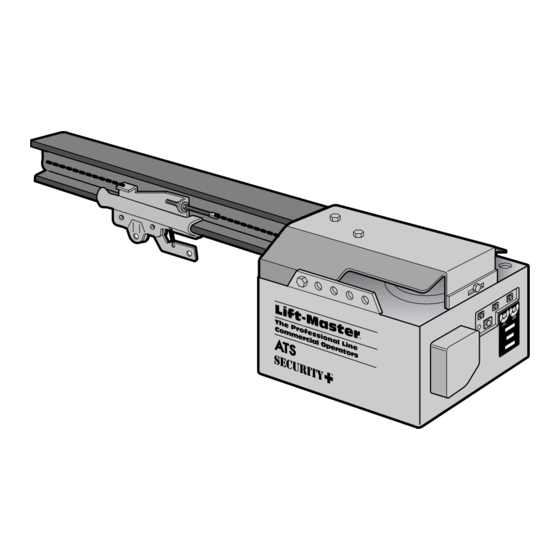
MODEL ATS 211R
COMMERCIAL DOOR OPENER
For Residential and Light Duty Commercial Use
Install on Sectional Doors Only
OWNER'S MANUAL
Please read this manual and the enclosed safety materials carefully!
Fasten the manual near the garage door after installation.
The door WILL NOT CLOSE unless the Protector System
and properly aligned.
Periodic checks of the opener are required to ensure safe operation.
The model number label is located on the operator cover.
The Chamberlain Group, Inc.
845 Larch Avenue,
Elmhurst, Illinois 60126
®
is connected
®
Advertisement
Table of Contents

Related Manuals for Chamberlain LiftMaster Professional ATS 211R


Summary of Contents for Chamberlain LiftMaster Professional ATS 211R
- Page 1 The door WILL NOT CLOSE unless the Protector System and properly aligned. Periodic checks of the opener are required to ensure safe operation. The model number label is located on the operator cover. The Chamberlain Group, Inc. 845 Larch Avenue, Elmhurst, Illinois 60126 ®...
-
Page 2: Table Of Contents
When you see this Safety Symbol on the following pages, it will alert you to the possibility of damage to your garage door and/or the garage door opener if you do not comply with the corresponding instructions. Read the instructions carefully. -
Page 3: You'll Need Tools
During assembly, installation and adjustment of the opener, instructions will call for hand tools shown below. Carpenter's Level Stepladder 1/2" and 7/16" Sockets WARNING An unbalanced garage door might not reverse when required and someone under the door could be seriously injured or killed. If your garage door binds, sticks or is out of balance, call for professional garage door service. -
Page 4: Illustration Of Door Installation
Before you begin, survey your garage area. Do any of the following conditions apply to you? Horizontal and vertical reinforcement is needed for lightweight garage doors (fiberglass, steel, aluminum, door with glass panels, etc.). See page 19 for details. Header Wall across width of door Safety Reversing Sensor Based on your particular requirements, there are... -
Page 5: Opener Carton Inventory
Your garage door opener is packaged in two cartons which contain all parts illustrated below. If anything is missing, carefully check the packing material. Parts may be "stuck" in the foam. Hardware for assembly and installation is listed below. Mounting Hardware... -
Page 6: Assembly Section: Pages
Assembly Section: Pages 6 – 7 Assembly Step 1 Attach the Rail to the Opener • Place the opener on packing material to protect the cover. • Remove the (2) 5/16"-18x1/2" washered screws mounted in the top of the opener. •... -
Page 7: Tighten The Chain
NOTE: During future maintenance, ALWAYS pull the manual release handle to disconnect trolley before adjusting chain. You have now finished assembling your garage door opener. Please read the following warnings before proceeding to the installation section: IMPORTANT INSTALLATION INSTRUCTIONS WARNING... -
Page 8: Installation Section: Pages
Installation Section: Pages 8 – 20 Installation Step 1 Determine Header Bracket Location Vertical Guideline Header Wall • Open your door to the highest point of travel as shown. Draw an intersecting horizontal line on the header wall 2" above the high point. -
Page 9: Install The Header Bracket
Installation Step 2 Install the Header Bracket Fasten the Header Bracket to the Wall • Center the bracket on the vertical guideline with the bottom edge of the bracket on the horizontal line as shown (with the arrow pointing toward the ceiling). -
Page 10: Attach The Rail To The Header Bracket
Installation Step 3 Attach the Rail to the Header Bracket Header Wall Header Bracket Chain Pulley Bracket Garage Door • Position the opener on the garage floor below the header bracket. Use packing material as a protective base. If the door spring is in the way you'll need help. Have someone hold the opener securely on a temporary support to allow the rail to clear the spring. -
Page 11: Position The Opener
Installation Step 4 Position the Opener A 2x4 laid flat is convenient for setting an ideal door-to-rail distance. • Raise the opener onto a stepladder. Door • If the top panel hits the trolley when you raise the door, pull down on the trolley release arm to disconnect the inner and outer sections. -
Page 12: Hang The Opener
Installation Step 5 Hang the Opener Two representative installations are shown. Yours may be different. Hanging brackets should be angled, Figure 1, to provide rigid support. On finished ceilings, Figure 2, attach a sturdy metal bracket to structural supports in ceiling before installing the opener. -
Page 13: Install The Door Control
Installation Step 6 Install the Door Control • Strip 1/4" of insulation from one end of the bell wire; connect the wire to the two screw terminals on the back of the Door Control: white to 2 and white/red to 1. •... -
Page 14: Install The Light
4-1/2 minutes when power is connected. Then the light will turn OFF. • If the bulb burns out prematurely due to vibration, replace with a "Garage Door Opener" bulb. Installation Step 8 Attach the Manual Release Rope and Handle... -
Page 15: Electrical Requirements
If permanent wiring is required by your local code, refer to the following procedure: WARNING To prevent electrocution, remove power from the garage door opener and from the circuit you plan to use for the permanent connection. To make a permanent connection through the 7/8"... -
Page 16: The Protector System
To protect small children, install the safety reversing sensor so that the beam will be no higher than 4-6" above the garage floor. Disconnect power to the garage door opener before installing the safety reversing sensor. Facing the door from inside the garage ®... -
Page 17: Install The Safety Reversing Sensor
Installation Step 10 Install the Safety Reversing Sensor (Receiving and Sending Eyes) Figures 1, 2 and 3 show recommended assembly of bracket(s) and "C" wrap based on the wall installation of the sensors on each side of the garage door as shown on page 16, or on the garage door tracks themselves. - Page 18 • Center each sensor unit in a "C" wrap with lenses pointing toward each other across the door (see Figure 6). • Secure sensors with the hardware shown. Finger tighten the wing nut on the receiving eye to allow for final adjustment. Securely tighten the sending eye wing nut.
-
Page 19: Fasten The Door Bracket And Plate
Installation Step 11 Fasten Door Bracket & Plate INSTALLATION STEP 11 Fasten the Door Bracket A horizontal reinforcement brace should be long enough to be secured to two or three vertical supports. A vertical reinforcement brace should cover the height of the top panel. Figure 1 shows one piece of angle iron as the horizontal brace. -
Page 20: Connect The Door Arm To The Trolley
Installation Step 12 Connect Door Arm to Trolley Make sure garage door is fully closed. Pull the manual release handle to disconnect the outer trolley from the inner trolley. Slide the outer trolley back (away from the door) about 2” as shown in Figures 1, 2 and 3. -
Page 21: Adjustment Section: Pages
Adjustment Section: Pages 21 – 23 Adjustment Step 1 Adjust the UP and DOWN Limits Do not make any limit adjustments until the Safety Reversing Sensors are completely installed. Limit adjustment settings regulate the points at which the door will stop when moving up or down. The door will stop in the up direction if anything interferes with door travel. -
Page 22: Force Adjustments
Adjustment Step 2 Adjust the Force Force adjustment controls are located on the back panel of the opener. Force adjustment settings regulate the amount of power required to open and close the door. The door will stop in the up direction if anything interferes with its travel. -
Page 23: Test The Protector System
Professional service is required if the opener closes the door when the safety reversing sensor is obstructed. The garage door opener will not close from a remote control transmitter if the indicator light in either sensor is off (alerting you to the fact that the sensor is misaligned or obstructed). -
Page 24: Operation Safety Instructions
Repairs to cables, spring assemblies and other hardware must be made by a professional garage door person. 7. Disconnect the electric power from the garage door opener before making any repairs or removing the covers. -
Page 25: Operation Of Your Opener
Activate the opener with any of the following: • The Door Control. Hold push button down until the door starts to move. • A Remote Control Transmitter. Hold push button down until the door starts to move. • The Outside Keylock or Keyless Entry. (See Accessories) When the opener is activated with the safety reversing sensor installed and correctly aligned:... -
Page 26: Model 96Lm Remote Control
Remote Control Code Select a remote control push button to operate the opener. The large button is recommended for use with a garage door opener. 1. Press and hold the selected remote control push button. See Figure 1. 2. Press and release the “Smart” (learn) button on the opener panel, Figure 2. -
Page 27: Model 58Lm Door Control
SECURITY Multi-Function Door Control - Model 58LM (OPTIONAL) NOTICE: To ensure the proper functioning of your new Garage Door Opener, please remove all old or previous push buttons/door control panels. • Strip 1/4" of insulation from one end of the bell wire;... -
Page 28: Model 68Lm Door Control
SECURITY Multi-Function Door Control - Model 68LM (OPTIONAL) NOTE: To ensure the proper functioning of your new Garage Door Opener, remove all old or previous push buttons/door control panels. Locate the door control within sight of the door at a minimum height of 5 feet where small children cannot reach, and away from all moving parts of the door and door hardware. -
Page 29: Model 67Lm Keyless Entry
Enter. 2. Press and hold the light button on the door control. 3. Press and hold the door control push bar. 4. After the opener light blinks, release all buttons. Garage Door Opener Receiver (With Smart Button) Smart Indicator... -
Page 30: Having A Problem
Situation Probable Cause & Solution 1. Does the opener have electric power? Plug a lamp into the outlet. If it doesn't light, The opener doesn't check the fuse box or the circuit breaker. (Some outlets are controlled by a wall switch.) operate from either the Door Control or 2. - Page 31 The opener light: . . . doesn't turn on: Replace the light bulb (75 watts maximum). Use a standard neck garage door opener bulb if regular bulb burns out..doesn't turn off: Is the Light feature on ? Turn it off.
-
Page 32: Repair Parts, Rail Assembly
Rail Assembly Parts Installation Parts PART DESCRIPTION 41A4166 Door control push button 217A238 2-conductor bell wire, white & white/red 41A2828 Manual rope & handle assembly 12B374 Door bracket 12B380 Door bracket plate 41A4353 Header bracket w/clevis pin & fastener 41A4373A Safety sensor kit (receiving and sending eyes) with 3' 2-conductor bell wire attached... -
Page 33: Repair Parts, Opener Assembly
Opener Assembly Parts (Down) LIMIT SWITCH ASSY. Contact Brown Wire Grey Wire Drive Gear Center Limit (Up) Yellow Contact Contact Wire KEY PART DESCRIPTION 41C5069 Rail support bracket assembly kit 144B18 Pulley (Chain) 41C4470 Gear and sprocket assy. Complete with: Spring washer Thrust washer Retaining washer... -
Page 34: Accessories
Accessories Available for your Opener Model 81LM “Smart” Remote Control: Includes visor clip. Model 971LM SECURITY Single-Function Remote Control: Includes visor clip. Multi-Function Door Control Panel: Model 58LM Provides a Lock Feature which prevents operation of garage door LOC K LIG HT opener from portable remotes and a Light Feature for constant light. -
Page 35: Operation Of Optional Accessories Model 96Lm Remote Control
Access Door/Outside Quick Release Accessory...4, 34 Chain Tension ...4, 7, 31 Electrical Safety Warnings...2, 7, 15, 24 Garage Door Testing for balance, binding and sticking...3, 21, 22, 24 Determining high point of travel: ...8 Disabling existing locks...3, 7 Force Controls Adjustment procedures...22 Problems that might require force adjustments ...30, 31 Safety warnings ...22, 24... -
Page 36: How To Order Repair Parts
LIFTMASTER GARAGE DOOR OPENER ONE-YEAR LIMITED WARRANTY Chamberlain/LiftMaster warrants to the first retail purchaser of this product that it will be free from any defect in materials and/or workmanship for a period of twelve full months from the date of purchase. The product must be used in complete accordance with Lift-Master's instructions for installation, operation and care.