
Related Manuals for Icom iDAS IC-F3103D


Summary of Contents for Icom iDAS IC-F3103D
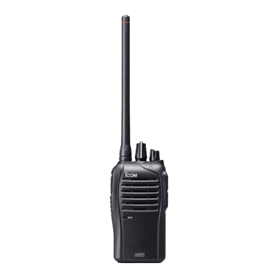
- Page 1 INSTRUCTION MANUAL VHF dPMR HANDHELD TRANSCEIVER iF3102D iF3103D UHF dPMR HANDHELD TRANSCEIVER iF4102D iF4103D The photo shows the VHF transceiver.
-
Page 2: Explicit Definitions
FOREWORD Thank you for choosing this Icom product. This product is designed and built with Icom’s state of the art technology and craftsmanship. With proper care this product should provide you with years of trouble-free operation. READ ALL INSTRUCTIONS carefully and completely before using the transceiver. -
Page 3: Voice Coding Technology
• The use of Icom transceiver with any equipment that is not man- ufactured or approved by Icom. Icom, Icom Inc. and Icom logo are registered trademarks of Icom Incorporated (Japan) in Japan, the United States, the United Kingdom, Germany, France, Spain, Russia, Australia, New Zealand, and/or other countries. -
Page 4: Precautions
Use and charge only specified Icom battery packs with Icom transceivers or Icom chargers. Only Icom battery packs are tested and approved for use with Icom transceivers or charged with Icom chargers. Using third-party or counterfeit battery packs or chargers may cause smoke, fire, or cause the battery to burst. - Page 5 DO NOT operate the transceiver near unshielded electrical blast- ing caps or in an explosive atmosphere. DO NOT push [PTT] when you do not actually intend to transmit. DO NOT operate or place the transceiver in direct sunlight or in areas with temperatures below –25°C or above +55°C.
-
Page 6: Table Of Contents
TABLE OF CONTENTS FOREWORD ..................i EXPLICIT DEFINITIONS ..............i VOICE CODING TECHNOLOGY ............ii PRECAUTIONS ................iii, iv 1 ACCESSORIES ................. 1–4 ■ Supplied accessories ..............1 ■ Accessory attachments .............. 1 2 PANEL DESCRIPTION ............5–13 ■ Front, top and side panels ............5 ■... - Page 7 4 dPMR OPERATION ............... 27–32 ■ dPMR operation ................ 27 ■ Receiving a call................. 28 ■ Transmitting a call ..............30 ■ Position data transmission ............32 ■ Status message transmission ........... 32 ■ Scrambler function ..............32 5 BATTERY CHARGING ............33–43 ■...
-
Page 8: Accessories
ACCESSORIES ■ Supplied accessories The following accessories are supplied with the transceiver. Battery pack* Flexible antenna (This illustration is for the VHF type.) Battery charger* Power adapter* Belt clip* Jack cover (with screws) * Not supplied, or the shape is different, depending on the version. ■... - Page 9 ACCESSORIES D Belt clip To attach the belt clip: ➥ Slide the belt clip in the direction of the arrow until the belt clip locks in place, and makes a ‘click’ sound. Belt clip Battery pack To detach the belt clip: q Remove the battery pack from the transceiver, if it is attached.
- Page 10 ACCESSORIES D Battery pack or case To attach the battery pack or case: q Fit the battery pack/case in the direction of the arrow, then close w Hook the latch until it makes a ‘click’ sound. Battery pack/case Latch To remove the battery pack/case: Be careful! The latch is tightly locked, so use caution when re- leasing it.
- Page 11 ACCESSORIES NEVER remove or attach the battery pack/case when the trans- ceiver is wet or soiled. This may result in water or dust getting into the transceiver, battery pack/case, and may result in them being damaged. NOTE: Keep the battery pack terminals clean. It’s a good idea to occasionally clean them.
-
Page 12: Panel Description
PANEL DESCRIPTION ■ Front, top and side panels ROTARY SELECTOR VOLUME ANTENNA CONTROL CONNECTOR LED INDICATOR PTT SWITCH Speaker SPEAKER- UPPER KEY MICROPHONE LOWER KEY JACK Microphone q ROTARY SELECTOR Rotate to select the pre-programmed memory channels or scan lists, depending on the pre-programming. w VOLUME CONTROL [VOL] Rotate to turn the power ON or OFF, and adjust the audio level. - Page 13 PANEL DESCRIPTION e LED INDICATOR (pp. 7–9) ➥ Lights red* while transmitting. * When the optional battery case is attached, the LED indicator lights orange. ➥ Lights green while receiving a signal, or when the squelch is open. ➥ Lights/blinks orange when the matched 2/5-tone code is re- ceived, depending on the presetting.
-
Page 14: Led Indicator
PANEL DESCRIPTION ■ LED indicator The LED indicator indicates the status of various parameters of the transceiver as follows; (Reference: R=Red, G=Green, O=Orange) • TX: Lights Red while transmitting a signal. • RX busy: In the Analog CH, lights Green while in the noise squelch opens. - Page 15 PANEL DESCRIPTION • Audible: Blinks slowly while in the audible mode after an acknowl- edgement is received. • Fast/Slow scan or voting: Blinks when the Fast/Slow scan or voting is activated. • Low Battery 1: You should charge the battery. (Slowly blinks.) •...
- Page 16 PANEL DESCRIPTION ■ LED indicator (Continued) • Emergency: Blinks when an Emergency call was received (Status or SDM call). G O R G O R G O R G O R • Emergency Locator Ringer Siren: Blinks while in the Emergency locator, Ringer or Siren is acti- vated.
-
Page 17: Programmable Function Keys
■ Programmable function keys The following functions can be assigned to the [Upper] and [Lower] programmable function keys. Consult your Icom dealer or system operator for details concerning your transceiver’s programming. SCAN Push to start and cancel the scanning operation. - Page 18 PANEL DESCRIPTION ■ Programmed function keys (Continued) MONITOR, MONITOR (AUDIBLE) ➥ Push to turn the CTCSS (DTCS) or 2/5-tone squelch Mute ON or OFF. • Only during LMR operation, push to open any squelch func- tions, or deactivate any mute functions. •...
- Page 19 PANEL DESCRIPTION DTMF AUTODIAL Push to transmit a programmed DTMF code. WIDE/NARROW Push to toggle the IF bandwidth between Wide, Mid* or Narrow. * Depending on the presetting, Mid channel width may not be se- lectable. Ask your dealer for details. CALL, CALL A, CALL B Push to transmit a 2/5-tone code.
- Page 20 PANEL DESCRIPTION ■ LED indicator (Continued) SIREN Hold down for 1 second to emit a siren sound. This function can be used for situations other than an emergency alert, such as a security alarm for example. The transceiver emits the siren sound until the power is turned OFF.
-
Page 21: Basic Operation
BASIC OPERATION ■ Turning ON the power Prior to using the transceiver for the first time, the battery pack must be fully charged for optimum life and operation. (p. 33) [VOL] ➥ Rotate [VOL] to turn ON the power. D Battery type selection The battery type must be selected according to the battery pack or case when it is changed, but only the first time it is used. -
Page 22: Channel Selection
BASIC OPERATION ■ Channel selection Several types of channel selections are available. Methods may dif- fer, depending on the presetting. To select a desired operating channel, do one of the following. • Rotate [ROTARY SELECTOR]. • Push one of memory channel keys, [MR-CH 1] to [MR-CH 4]. •... -
Page 23: Call Procedure
BASIC OPERATION ■ Call procedure When your system employs tone signalling (excluding CTCSS and DTCS), the tone call procedure may be necessary prior to voice transmission. The tone signalling that is employed in the transceiver may be a selective calling system, which allows you to call only specific station(s), and prevent unwanted stations from contacting you. -
Page 24: Receiving And Transmitting
BASIC OPERATION ■ Receiving and transmitting CAUTION: Transmitting without an antenna will damage the transceiver. See page 1 for antenna attachment. Receiving: q Rotate [VOL] to turn ON the power. w Rotate [ROTARY SELECTOR], or push one of the memory chan- nel keys, [MR-CH 1] to [MR-CH 4], to select a channel. - Page 25 BASIC OPERATION D Transmitting notes • Transmit inhibit function The transceiver has several inhibit functions, which restrict trans- mission under the following conditions: - The channel is muted. (PMR operation only) - The channel is busy. - A signal with the un-matched (or matched) CTCSS (or DTCS) tone is received.
- Page 26 BASIC OPERATION D DTMF transmission If the transceiver has [DTMF Autodial] assigned to it, the automatic DTMF transmission function is usable. ➥ Push [DTMF Autodial] to transmit the DTMF code. D Receiving a Stun, Kill and Revive command The dispatcher can send a signal that will stun, kill or revive your transceiver.
-
Page 27: Setting The Microphone Gain
BASIC OPERATION ■ Setting the microphone gain Adjusts the microphone gain. q Rotate [VOL] to turn the trans- [ROTARY SELECTOR] ceiver power OFF. [VOL] w Set [ROTARY SELECTOR] to Channel 16. e While holding down [Upper], ro- tate [VOL] to turn ON the power and enter the microphone gain adjustment mode. -
Page 28: Setting The Squelch Level
BASIC OPERATION ■ Setting the squelch level The squelch circuit mutes the received audio signal, depending on the signal strength. q Rotate [VOL] to turn the trans- [ROTARY SELECTOR] ceiver power OFF. [VOL] w Set [ROTARY SELECTOR] to any channel other than Chan- nel 16. -
Page 29: Setting The Beep Level
BASIC OPERATION ■ Setting the Beep level The beep function can be turned ON or OFF, and its level can be adjusted between 1 and 5, or 1 (linked) and 5 (linked). When a Linked option is selected, the beep level is adjustable with [VOL]. q Rotate [VOL] to turn the trans- [ROTARY SELECTOR] ceiver power OFF. -
Page 30: Setting The Ringer Level
BASIC OPERATION ■ Setting the Ringer level The Ringer level can be adjusted between 1 and 5, or 1 (Linked) and 5 (Linked). When a Linked option is selected, the Ringer level is adjustable with [VOL]. q Rotate [VOL] to turn the trans- [ROTARY SELECTOR] ceiver power OFF. -
Page 31: Output Power Level Selection
BASIC OPERATION ■ Output power level selection If the transceiver has [High/Low] assigned to it, the transmit output power level can be selected, depending on the presetting. When the battery case is selected as the battery type, or the bat- tery voltage drops to a low power level and the LED indicator sta- tus is “Low Battery 2,”... -
Page 32: Lone Worker Emergency Call
BASIC OPERATION ■ Lone Worker Emergency Call When the Lone Worker function is turned ON, and no operation is performed for the specified time period*, the transceiver enters the emergency mode, and then the countdown for the emergency call transmission starts. After the specified time period* has passed, an emergency call is automatically transmitted once, or repeatedly*. -
Page 33: Emergency Call
BASIC OPERATION ■ Emergency Call When [Emergency] is held down for the specified time period*, the emergency signal is transmitted once, or repeatedly, on the speci- fied emergency channel. A repeat emergency signal is automatically transmitted until you turn the power OFF. Depending on the pre-programmed settings, receiving a matching 5-tone code cancels the transmission. -
Page 34: Dpmr Operation
dPMR OPERATION ■ dPMR operation The transceiver provides digital Private Mobile Radio (dPMR) op- eration that meets the 6.25 kHz bandwidth requirements for narrow band operation. This increases the efficiency of channel allocation and use of the spectrum. NOTE: During dPMR operation, BIIS 1200 operation is dis- abled. - Page 35 dPMR OPERATION D Receiving a Group call q When a Group call is received: • The LED indicator blinks orange. • Beeps sound and the mute is released. w Hold down [PTT], then speak into the microphone. NOTE: Only one station is allowed to speak at the same time.
- Page 36 dPMR OPERATION ■ Receiving a call (Continued) D Receiving a Status Polling call If a Status Polling call is received, the transceiver will automatically transmit its current status. D Receiving an Ambience Listening call If an Individual call with an Ambience Listening command is re- ceived from a specified station, the transceiver will automatically transmit its microphone audio.
-
Page 37: Transmitting A Call
dPMR OPERATION ■ Transmitting a call dPMR operation allows you to make a call to a specific station (In- dividual call) or to a particular group (Talkgroup call). Other digital mode transceivers on the channel will not receive a call that does not match their individual or talkgroup ID and/or CC. - Page 38 dPMR OPERATION ■ Transmitting a call (Continued) D Transmitting an Emergency call When [Emergency] is held down for the specified time period, the emergency signal (digital command) is transmitted once or repeat- edly* on the specified emergency channel. When no emergency channel is specified, the signal is transmitted on the operating channel.
-
Page 39: Position Data Transmission
dPMR OPERATION ■ Position data transmission When an optional HM-171GP or any other GPS receiver is con- nected to the transceiver, the position (longitude and latitude) data can automatically be transmitted when: • When [PTT] is released. - Set the ‘Send with Logoff’ item as ‘Enable.’ •... -
Page 40: Battery Charging
BATTERY CHARGING ■ Caution (for the BP-264 mh battery R DANGER! KEEP battery packs away from fire. Fire or heat may cause them to rupture or explode. Dispose of an used battery pack in accordance with local regulations. R DANGER! NEVER immerse the battery pack in water. If the bat- tery pack becomes wet, be sure to wipe it dry BEFORE attaching it to the transceiver. - Page 41 BATTERY CHARGING If your Ni-MH battery pack seems to have no capacity, even after being charged, completely discharge it by leaving the power ON overnight. Then, fully charge the battery pack again. If the battery pack still does not retain a charge (or only very little charge), a new battery pack must be purchased.
-
Page 42: Caution (For The Bp-265 Li-Ion Battery )
BATTERY CHARGING ■ Caution (for the BP-265 Li-ion battery Misuse of Li-ion batteries may result in the following hazards: smoke, fire, or the battery may rupture. Misuse can also cause damage to the battery or degradation of battery performance. D Battery caution R DANGER! DO NOT hammer or otherwise impact the battery. - Page 43 R WARNING! Immediately stop using the battery if it emits an abnor- mal odor, heats up, or is discolored or deformed. If any of these condi- tions occur, contact your Icom dealer or distributor. R WARNING! NEVER use deteriorated battery packs. They could cause a fire.
- Page 44 The charger is not waterproof. CAUTION: DO NOT charge the battery outside of the specified tem- perature range: BC-193 (+10˚C to +40˚C). Icom recommends charging the battery at +20˚C. The battery may heat up or rupture if charged out of the specified temperature range.
-
Page 45: Battery Chargers
BATTERY CHARGING ■ Battery chargers D Using the BC-191 to rapid charge the BP-264 The BC-191 provides rapid charging of the Ni-MH battery pack (BP-264 only). Never use for any other battery pack. Charging time period: Approximately 2 hours (for the BP-264) The following item is additionally required: •... - Page 46 BATTERY CHARGING D Using the BC-192 to regular charge the BP-264 The BC-192 provides regular charging of the Ni-MH battery pack (BP-264 only). Never use for any other battery pack. Charging time period (with BC-147S): Approximately 16 hours (for the BP-264) The following item is additionally required: •...
- Page 47 BATTERY CHARGING D Using the BC-193 to rapid charge the BP-265 The BC-193 provides rapid charging of the Li-ion battery pack (BP-265 only). Never use for any other battery pack. Charging time period: Approximately 2.5 hours (for the BP-265) The following item is additionally required: •...
- Page 48 BATTERY CHARGING D Using the BC-197 to rapid charge the BP-264 or BP-265 The BC-197 rapidly charges up to six battery packs. Charging time for BP-264: Approximately 2 hours Charging time for BP-265: Approximately 2.5 hours The following additional item is required: •...
- Page 49 BATTERY CHARGING There are two types of BC-197 chargers for the IC-F3102D, IC- F3103D, IC-F4102D or IC-F4103D; one is for Ni-MH batteries, and the other is for Li-ion batteries. Before you purchase a BC-197, check the type of battery you are using, and then be sure to choose the suitable charger.
- Page 50 BATTERY CHARGING IMPORTANT: Ensure the tabs on the battery pack are correctly aligned with the guide rails inside the charger. Tabs BC-191, BC-192, BC-193 Guide rail...
-
Page 51: Battery Case
BATTERY CASE ■ Optional battery case (BP-263) When using the optional battery case, install 6 × AA (LR6) size alkaline batteries, as illustrated below. q Remove the battery case, if it is attached. (pp. 3, 4) w Install 6 × AA (LR6) size alkaline batteries. •... -
Page 52: Options
OPTIONS D BATTERY PACK Battery pack Voltage Capacity Battery life* Battery case for BP-263 —* AA (LR6) × 6 alkaline 12 hrs. BP-264 7.2 V 1400 mAh (typ.) 11.3 hrs. 17.5 hrs. 1900 mAh (min.) BP-265 7.4 V 2000 mAh (typ.) 16.1 hrs. - Page 53 OPTIONS • BC-197 muLti charger For rapid simultaneously charging of up to six battery packs. A power adapter may be supplied with the charger, depending on the version. There are two types of BC-197 chargers for the IC- F3102D/IC-F3103D/IC-F4102D/IC-F4103D. BC-197 Charger Type Chargeable Battery Charging time With AD-120*...
- Page 54 OPTIONS D OTHER OPTIONS • AD-98FSC antenna connector converter Allows you to connect an external antenna with a BNC connector. • HM-158L/HM-159L speaker microphone Combination speaker-microphone that provides convenient op- eration while hanging the transceiver on your belt. • HM-171GP speaker microphone GPS speaker-microphone for BIIS and Digital modes operation.
-
Page 55: Vox Function
OPTIONS ■ VOX function The transceiver has a VOX function, which allows you hands-free operation. An optional headset (HS-94/HS-95/HS-97) and a plug adapter cable (OPC-2004) are additionally required for operation. • The VOX (voice operated transmission) function starts transmitting when you speak into the microphone, without needing to push the PTT switch;... - Page 56 OPTIONS D Turning the VOX function ON or OFF The VOX function can be turned ON or OFF when turning the trans- ceiver power ON. q Rotate [VOL] to turn the trans- [ROTARY SELECTOR] ceiver power OFF. [VOL] w Set [ROTARY SELECTOR] to any channel other than Chan- nel 16.
- Page 57 OPTIONS D Setting the VOX gain The VOX sensitivity level can be adjusted from 1 (minimum) to 10 (maximum). [ROTARY SELECTOR] q Connect the optional headset [VOL] (HS-94, HS-95 or HS-97) and OPC-2004. (p. 48) w Rotate [VOL] to turn the trans- ceiver power OFF.
-
Page 58: Information
INFORMATION ■ Disposal The crossed-out wheeled-bin symbol on your product, lit- erature, or packaging reminds you that in the European Union, all electrical and electronic products, batteries, and accumulators (rechargeable batteries) must be taken to designated collection locations at the end of their working life. Do not dispose of these products as unsorted municipal waste. - Page 59 MEMO...
- Page 60 A7061D-1EU-2a Printed in Japan © 2012–2018 Icom Inc. 1-1-32 Kamiminami, Hirano-ku, Osaka 547-0003, Japan Printed on recycled paper with soy ink.