Table of Contents
Advertisement
Quick Links
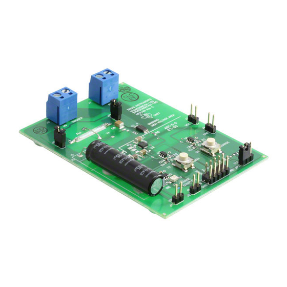
This user's guide describes the characteristics, operation, and use of the TPS65560EVM-165 Evaluation
Module (EVM). This EVM demonstrates the Texas Instruments TPS65560 Integrated Photo Flash
Chargers with IGBT Drivers. This user's guide includes setup instructions, a schematic diagram, a bill of
materials, and printed-circuit board layout drawings for the evaluation module.
...................................................................................................................
1
..........................................................................................................................
2
3
4
5
1
2
3
4
......................................................................................................................
1
2
1
Introduction
The TPS65560 is a highly integrated flyback converter used to charge photo flash capacitors. The Texas
Instruments TPS65560EVM-165 evaluation module (EVM) helps designers evaluate the operation and
performance of this device.
The EVM contains one fully functional photo flash charger capable of charging a photo flash capacitor to
320 volts from a battery with voltage between 1.6 and 12 volts. The EVM also provides a flash lamp and
trigger circuit to help the designer evaluate the charging characteristics. The onboard lamp circuit can be
disabled so that the EVM can be connected to a user-supplied lamp and trigger circuit.
SLVU155B - March 2006 - Revised March 2008
Submit Documentation Feedback
.................................................................................................................
............................................................................................
.........................................................................................................
.....................................................................................................
...........................................................................................................
.......................................................................................................
......................................................................................
SLVU155B - March 2006 - Revised March 2008
TPS65560EVM-165
.......................................................................
List of Figures
List of Tables
User's Guide
1
2
5
7
8
5
5
6
6
2
8
TPS65560EVM-165
1
Advertisement
Table of Contents

Related Manuals for Texas Instruments TPS65560EVM-165


Summary of Contents for Texas Instruments TPS65560EVM-165
-
Page 1: Table Of Contents
SLVU155B – March 2006 – Revised March 2008 TPS65560EVM-165 This user’s guide describes the characteristics, operation, and use of the TPS65560EVM-165 Evaluation Module (EVM). This EVM demonstrates the Texas Instruments TPS65560 Integrated Photo Flash Chargers with IGBT Drivers. This user’s guide includes setup instructions, a schematic diagram, a bill of materials, and printed-circuit board layout drawings for the evaluation module. -
Page 2: Setup
This section describes the jumpers and connectors on the EVM as well as how to properly connect, set up, and use the TPS65560EVM-165. WARNING The TPS65560EVM-165 produces high voltage and is designed to charge the bulk flash capacitor to more than 320 volts. This capacitor can maintain this voltage for a long time, even after the input power has been removed from the board. - Page 3 10. Release the Charge button when the green Charge Complete LED (D2) illuminates. 11. Push the Flash switch to flash lamp. 12. Repeat steps 9 through 11 as needed. SLVU155B – March 2006 – Revised March 2008 TPS65560EVM-165 Submit Documentation Feedback...
- Page 4 12. Push and hold the Charge switch to start charging the flash capacitor. 13. Release Charge switch when the green Charge Complete LED (D2) illuminates. 14. Push the Flash switch to flash lamp. Repeat steps 12 through 14 as necessary. TPS65560EVM-165 SLVU155B – March 2006 – Revised March 2008 Submit Documentation Feedback...
-
Page 5: Board Layout
Figure 4 show the board layout for the TPS65560EVM-165 PCB. The nodes with high-switching frequencies and currents are kept as short as possible to minimize trace inductance. Careful attention has been given to the routing of high-frequency current loops and a single-point grounding scheme is used for all high-current and high-voltage traces. -
Page 6: Top Layer Routing
Board Layout Figure 3. Top Layer Routing Figure 4. Bottom Layer Routing TPS65560EVM-165 SLVU155B – March 2006 – Revised March 2008 Submit Documentation Feedback... -
Page 7: Schematic And Bill Of Materials
Schematic and Bill of Materials Schematic and Bill of Materials This section provides the TPS65560EVM-165 schematic and bill of materials. Schematic SLVU155B – March 2006 – Revised March 2008 TPS65560EVM-165 Submit Documentation Feedback... -
Page 8: Related Documentation From Texas Instruments
Related Documentation From Texas Instruments Bill of Materials Table 2. TPS65560EVM-165 Bill of Materials Count RefDes Value Description Size Part Number 10 µF C1, C4 Capacitor, Ceramic, 16V, X7R, 10% 1206 C3216X7R1C106KT 4.7 µF Capacitor, Ceramic, 25V, X7R, 10%... - Page 9 EVALUATION BOARD/KIT IMPORTANT NOTICE Texas Instruments (TI) provides the enclosed product(s) under the following conditions: This evaluation board/kit is intended for use for ENGINEERING DEVELOPMENT, DEMONSTRATION, OR EVALUATION PURPOSES ONLY and is not considered by TI to be a finished end-product fit for general consumer use. Persons handling the product(s) must have electronics training and observe good engineering practice standards.
- Page 10 IMPORTANT NOTICE Texas Instruments Incorporated and its subsidiaries (TI) reserve the right to make corrections, modifications, enhancements, improvements, and other changes to its products and services at any time and to discontinue any product or service without notice. Customers should obtain the latest relevant information before placing orders and should verify that such information is current and complete.