
Related Manuals for Texas Instruments TPS65910 EVM


Summary of Contents for Texas Instruments TPS65910 EVM
- Page 1 Using the TPS65910 EVM, A Multichannel Power-management IC, 3 Buck, 1 Boost, and 8 LDOs User's Guide Literature Number: SWCU065E March 2010 – Revised May 2011...
- Page 2 For details of the EEPROM sequence please refer to the corresponding user guide in the “Application Notes” section on the TPS65910x folder page. Applications • Embedded application processor power • Handheld/portable systems SWCU065E – March 2010 – Revised May 2011 Introduction Submit Documentation Feedback Copyright © 2010–2011, Texas Instruments Incorporated...
- Page 3 One configurable general-purpose input/output (GPIO) • DCDCs switching synchronization through internal or external 3-MHz clock • Backup battery charger TPS65910 EVM Power Capabilities Table 1. TPS65910 EVM Resources Summary POWER RESOURCE TYPE VOLTAGE RANGE (V) (mA) SMPS (buck) 1.5, 1.8, 2.5, 3.3...
- Page 4 Schematic www.ti.com Figure 1. TPS65910 EVM Schematic SWCU065-001 Introduction SWCU065E – March 2010 – Revised May 2011 Submit Documentation Feedback Copyright © 2010–2011, Texas Instruments Incorporated...
-
Page 5: Connector And Test Point Descriptions
C interfaces: one is a general-purpose interface to control the internal configuration registers, the second is dedicated to SmartReflex applications such as dynamic voltage frequency scaling (DVFS) or adaptive voltage scaling (AVS). SWCU065E – March 2010 – Revised May 2011 Introduction Submit Documentation Feedback Copyright © 2010–2011, Texas Instruments Incorporated... - Page 6 Both these signals can be used to control the LDO and SMPS power supplies. SCLSR_EN1 Please refer details on programming the internal register to achieve this function. Introduction SWCU065E – March 2010 – Revised May 2011 Submit Documentation Feedback Copyright © 2010–2011, Texas Instruments Incorporated...
-
Page 7: Test Point Descriptions
Variable 6-V power supply capable of supplying 6 A current • Voltmeter • Oscilloscope • Windows PC with a universal serial bus (USB) port • USB-to-GPIO converter SWCU065E – March 2010 – Revised May 2011 Introduction Submit Documentation Feedback Copyright © 2010–2011, Texas Instruments Incorporated... - Page 8 8-bit hexadecimal value in the Value field. Individual bits can be toggled either by selecting the drop-down menu or by double-clicking the field. SWCU065E – March 2010 – Revised May 2011 Introduction Submit Documentation Feedback Copyright © 2010–2011, Texas Instruments Incorporated...
- Page 9 GUI Information www.ti.com Figure 2. GUI Snapshot – Register Properties SWCU065E – March 2010 – Revised May 2011 Introduction Submit Documentation Feedback Copyright © 2010–2011, Texas Instruments Incorporated...
- Page 10 The Register Map tab provides an alternative way to access the device registers. Also in this view, the bits and complete words can be read or written through the I C bus. SWCU065E – March 2010 – Revised May 2011 Introduction Submit Documentation Feedback Copyright © 2010–2011, Texas Instruments Incorporated...
- Page 11 I/O Flag tab on the menu bar. For mapping of the I/O lines, refer to the TPS65910 schematic and datasheet for the GPIO-to-USB adapter at http://focus.ti.com/docs/toolsw/folders/print/usb-to-gpio.html. SWCU065E – March 2010 – Revised May 2011 Introduction Submit Documentation Feedback Copyright © 2010–2011, Texas Instruments Incorporated...
-
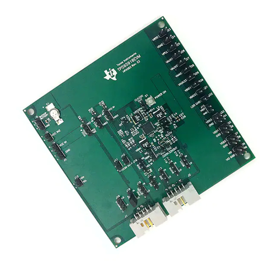
Page 12: Evm Assembly Drawings And Layout
EVM Assembly Drawings and Layout The following figures show the design of the TPS65910 EVM printed circuit board. The EVM has been designed using a 4-layer, 2-ounce, 4-inch × 4-inch copper-clad circuit board with all components on the top side and all active traces to the top to let the user easily view, probe, and evaluate the TPS65910 IC. - Page 13 EVM Assembly Drawings and Layout www.ti.com SWCU065-006 Figure 6. TPS65910 EVM Top Layer (L1) SWCU065E – March 2010 – Revised May 2011 Introduction Submit Documentation Feedback Copyright © 2010–2011, Texas Instruments Incorporated...
- Page 14 EVM Assembly Drawings and Layout www.ti.com SWCU065-007 Figure 7. TPS65910 EVM Internal Layer (L2) SWCU065E – March 2010 – Revised May 2011 Introduction Submit Documentation Feedback Copyright © 2010–2011, Texas Instruments Incorporated...
- Page 15 EVM Assembly Drawings and Layout www.ti.com SWCU065-008 Figure 8. TPS65910 EVM Internal Layer (L3) SWCU065E – March 2010 – Revised May 2011 Introduction Submit Documentation Feedback Copyright © 2010–2011, Texas Instruments Incorporated...
- Page 16 EVM Assembly Drawings and Layout www.ti.com SWCU065-009 Figure 9. TPS65910 EVM Bottom Copper (L4) SWCU065E – March 2010 – Revised May 2011 Introduction Submit Documentation Feedback Copyright © 2010–2011, Texas Instruments Incorporated...
-
Page 17: List Of Materials
List of Materials www.ti.com List of Materials Table 11 lists the EVM components as configured according to the schematic shown in Figure Table 11. TPS65910 EVM Bill of Materials COUNT REFDES VALUE DESCRIPTION SIZE PART NUMBER Capacitor, 0.2 F Electric Double... - Page 18 List of Materials www.ti.com Table 11. TPS65910 EVM Bill of Materials (continued) COUNT REFDES VALUE DESCRIPTION SIZE PART NUMBER TP1, TP2, TP3, Through Hole, TP4, TP5, TP6, PEC01SAAN PEC01SAAN Sullins 0.040 Diameter IC, Integrated TPS65910RSL Power TPS65910RSL Management 32.768 kHz Crystal 1.50 x 3.20 mm...
-
Page 19: Regulatory Compliance Information
Any exceptions to this are strictly prohibited and unauthorized by Texas Instruments unless user has obtained appropriate experimental/development licenses from local regulatory authorities, which is responsibility of user including its acceptable authorization. - Page 20 FCC Interference Statement for Class B EVM devices This equipment has been tested and found to comply with the limits for a Class B digital device, pursuant to part 15 of the FCC Rules. These limits are designed to provide reasonable protection against harmful interference in a residential installation. This equipment generates, uses and can radiate radio frequency energy and, if not installed and used in accordance with the instructions, may cause harmful interference to radio communications.
- Page 21 Also, please do not transfer this product, unless you give the same notice above to the transferee. Please note that if you could not follow the instructions above, you will be subject to penalties of Radio Law of Japan. Texas Instruments Japan Limited (address) 24-1, Nishi-Shinjuku 6 chome, Shinjuku-ku, Tokyo, Japan http://www.tij.co.jp...
- Page 22 FDA Class III or similar classification, then you must specifically notify TI of such intent and enter into a separate Assurance and Indemnity Agreement. Mailing Address: Texas Instruments, Post Office Box 655303, Dallas, Texas 75265 Copyright © 2012, Texas Instruments Incorporated...
-
Page 23: Important Notice
IMPORTANT NOTICE Texas Instruments Incorporated and its subsidiaries (TI) reserve the right to make corrections, enhancements, improvements and other changes to its semiconductor products and services per JESD46, latest issue, and to discontinue any product or service per JESD48, latest issue. -
Page 24: Texas Instruments
Mouser Electronics Authorized Distributor Click to View Pricing, Inventory, Delivery & Lifecycle Information: Texas Instruments TPS659108EVM-583 TPS65910EVM-583 TPS659101EVM-583...