Table of Contents
Advertisement
Quick Links
The TPS65291EVM is an evaluation module (EVM) for the TPS65291 power management unit (PMU)
device, which is primarily used in gas and water meters. In addition to gas and water meters, the
TPS65291 device can be used in any low-power, portable industrial application powered from a single-cell
(1S) or dual-stacked (2S) Lithium-Ion (Li-Ion) battery.
This document provides a description of how to setup and configure the EVM for operation. This
document also includes hardware documentation, including the schematic, layout and bill of materials,as
well as software instructions for installing the IPG-UI graphical user interface (GUI).
1
2
1
2
3
4
5
6
7
8
9
10
11
12
...................................................................................................................
13
14
15
16
17
18
19
20
21
1
2
3
SLVUB61 - July 2017
Submit Documentation Feedback
.............................................................................................
...............................................................................................................
..............................................................................................
...........................................................................................
.............................................................................
.................................................................................
................................................................................
..................................................................................................
..............................................................................................
..................................................................................................
................................................................................................
.................................................................................................
.............................................................................................
...............................................................................................
.............................................................................................................
Copyright © 2017, Texas Instruments Incorporated
TPS65291 EVM User's Guide
Contents
...................................................................
List of Figures
......................................................................
................................................
................................................................
......................................................................
............................................................................
..........................................................
.......................................................................
...................................................................
................................................................
....................................................................
List of Tables
User's Guide
SLVUB61 - July 2017
..........................
TPS65291 EVM User's Guide
2
3
12
17
3
4
5
7
9
10
10
11
12
12
12
12
13
13
14
17
17
18
18
18
19
6
6
15
1
Advertisement
Table of Contents

Related Manuals for Texas Instruments TPS65291 EVM


Summary of Contents for Texas Instruments TPS65291 EVM
-
Page 1: Table Of Contents
TPS65291 SPI Project Introduction Tab in IPG-UI List of Tables ..................... TPS65291EVM Test Point List ....................TPS65291EVM Jumper List ......................Bill of Materials SLVUB61 – July 2017 TPS65291 EVM User's Guide Submit Documentation Feedback Copyright © 2017, Texas Instruments Incorporated... -
Page 2: Introduction (Board Overview)
Introduction (Board Overview) www.ti.com Trademarks MSP430 is a trademark of Texas Instruments. All other trademarks are the property of their respective owners. Introduction (Board Overview) The TPS65291EVM allows designers to evaluate the operation and performance of the TPS65291 PMU. The TPS65291EVM is simple to test, requiring only a single power supply at the input, a USB cable connected to a computer running the GUI, and a load at the output to measure performance. -
Page 3: Getting Started
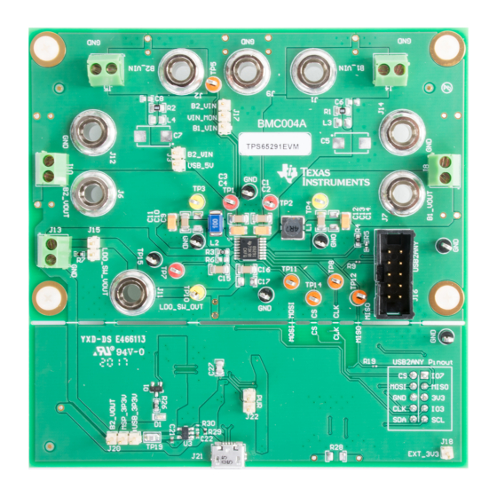
TPS65291EVM, highlighting important integrated circuits (ICs) and connections, the upper and lower sections of the PCB, and the interface between the EVM and a computer. SLVUB61 – July 2017 TPS65291 EVM User's Guide Submit Documentation Feedback Copyright © 2017, Texas Instruments Incorporated... -
Page 4: Tps65291Evm Block Diagram
MISO P4.5 PU.1 SPI_CS P2.0 Copyright © 2017, Texas Instruments Incorporated Figure 2. TPS65291EVM Block Diagram Power Connections This section describes the banana jacks and screw terminals for applying input power to and delivering output power from the TPS65291EVM. TPS65291 EVM User's Guide SLVUB61 –... -
Page 5: Tps65291 Test Setup: Power Supply And Multi-Meter Connections
J11 (LDO_SW_VOUT) and J12 (GND), or J13 (pin 1 = LDO_SW_VOUT, pin 1 = GND) — TheJ11 and J12 banana jacks and the J13 screw terminal are for attaching a load to draw power from LDO_SW. SLVUB61 – July 2017 TPS65291 EVM User's Guide Submit Documentation Feedback Copyright © 2017, Texas Instruments Incorporated... -
Page 6: Tps65291Evm Test Point List
Optional way to provide 3.3-V rail to B2_VOUT — MSP430 from TPS65291 BUCK2 USB_5V Optional way to provide 5-V VBUS rail to Not Installed TPS65291 from USB B2_VIN TPS65291 EVM User's Guide SLVUB61 – July 2017 Submit Documentation Feedback Copyright © 2017, Texas Instruments Incorporated... -
Page 7: Tps65291Evm Split With Ribbon Cable Between Usb2Any And Tps65291 Sections
Finally, grab the other end of the PCB firmly with pliers and bend back and forth slowly until the two sections separate. SLVUB61 – July 2017 TPS65291 EVM User's Guide Submit Documentation Feedback Copyright © 2017, Texas Instruments Incorporated... - Page 8 Click the Read All button again and most blue highlighted '1's will turn white or gray, indicating that these bits have not changed since the last time they were read. TPS65291 EVM User's Guide SLVUB61 – July 2017 Submit Documentation Feedback Copyright © 2017, Texas Instruments Incorporated...
-
Page 9: Successful Completion Read All Registers In Ipg-Ui
Click the Register0 row so that it is highlighted in gray and shows the Register0 contents. • Hover the mouse over Bit 1 to verify that B2_Enreg is Enabled, as shown in Figure SLVUB61 – July 2017 TPS65291 EVM User's Guide Submit Documentation Feedback Copyright © 2017, Texas Instruments Incorporated... -
Page 10: B2_Enreg Is Enabled By Default In Ipg-Ui
– Measure (with the DMM) and verify the voltage at J11 is approximately 2.8 V, or 5 to 10 mV below B2_VOUT because LDO_SW is configured as a load switch by default. TPS65291 EVM User's Guide SLVUB61 – July 2017 Submit Documentation Feedback Copyright © 2017, Texas Instruments Incorporated... -
Page 11: Enabling Ldo_Sw (Ldonsw_Enreg) In Ipg-Ui
Getting Started www.ti.com Figure 8. Enabling LDO_SW (LDOnSW_Enreg) in IPG-UI SLVUB61 – July 2017 TPS65291 EVM User's Guide Submit Documentation Feedback Copyright © 2017, Texas Instruments Incorporated... -
Page 12: Appendix Aevm Documentation
EVM Documentation Layout Figure 9 through Figure 14 show the board layout for the TPS65291EVM. Figure 9. Component Placement—Top Assembly Figure 10. Component Placement—Bottom Assembly EVM Documentation SLVUB61 – July 2017 Submit Documentation Feedback Copyright © 2017, Texas Instruments Incorporated... -
Page 13: Layout-Top Composite
Layout www.ti.com Figure 11. Layout—Top Composite Figure 12. Layout—Bottom Composite Figure 13. Top Layer Figure 14. Bottom Layer (Top View) SLVUB61 – July 2017 EVM Documentation Submit Documentation Feedback Copyright © 2017, Texas Instruments Incorporated... -
Page 14: Tps65291Evm Schematic
AVSS1 0.1 µF AVCC1 AVSS2 DVCC1 DVSS1 0.1 µF 1.5k DVCC2 DVSS2 EXT3V3_EN EXT3V3_FLT MSP430F5529IPN Copyright © 2017, Texas Instruments Incorporated Figure 15. TPS65291EVM Schematic EVM Documentation SLVUB61 – July 2017 Submit Documentation Feedback Copyright © 2017, Texas Instruments Incorporated... -
Page 15: Bill Of Materials
Vishay-Dale 1.5k RES, 1.5 k, 5%, 0.063 W, 0402 0402 CRCW04021K50JNED Vishay-Dale TP1, TP2, TP7 Test Point, Multipurpose, Red, TH Red Multipurpose Testpoint 5010 Keystone SLVUB61 – July 2017 EVM Documentation Submit Documentation Feedback Copyright © 2017, Texas Instruments Incorporated... - Page 16 RES, 4.99k ohm, 1%, 0.1W, 0603 0603 CRCW06034K99FKEA Vishay-Dale RES, 0, 5%, 0.25 W, 1206 1206 CRCW12060000Z0EA Vishay-Dale RES, 0, 5%, 0.063 W, 0402 0402 CRCW04020000Z0ED Vishay-Dale EVM Documentation SLVUB61 – July 2017 Submit Documentation Feedback Copyright © 2017, Texas Instruments Incorporated...
-
Page 17: Appendix B Software Installation And Setup Instructions
Install a shunt on header J20, shorting pin 1 (USB_3P3V) and pin 2 (MSP_3P3V). • Run the IPG-UI software by using the Windows Start Menu and navigating to the Texas Instruments folder, or by double-clicking the desktop icon, as shown in Figure Figure 16. -
Page 18: Creating New Ipg-Ui Project For The Tps65291
Click the Get Started button or the Register Map tab shown in Figure 21 to begin reading from and writing to registers to evaluate the TPS65291 device. Software Installation and Setup Instructions SLVUB61 – July 2017 Submit Documentation Feedback Copyright © 2017, Texas Instruments Incorporated... -
Page 19: Tps65291 Spi Project Introduction Tab In Ipg-Ui
Figure 21. TPS65291 SPI Project Introduction Tab in IPG-UI NOTE: At present, the IPG-UI software version is 2.5.0.3 and the TPS65291-SPI file version is 1.1. SLVUB61 – July 2017 Software Installation and Setup Instructions Submit Documentation Feedback Copyright © 2017, Texas Instruments Incorporated... - Page 20 STANDARD TERMS FOR EVALUATION MODULES Delivery: TI delivers TI evaluation boards, kits, or modules, including any accompanying demonstration software, components, and/or documentation which may be provided together or separately (collectively, an “EVM” or “EVMs”) to the User (“User”) in accordance with the terms set forth herein.
- Page 21 FCC Interference Statement for Class B EVM devices NOTE: This equipment has been tested and found to comply with the limits for a Class B digital device, pursuant to part 15 of the FCC Rules. These limits are designed to provide reasonable protection against harmful interference in a residential installation.
- Page 22 【無線電波を送信する製品の開発キットをお使いになる際の注意事項】 開発キットの中には技術基準適合証明を受けて いないものがあります。 技術適合証明を受けていないもののご使用に際しては、電波法遵守のため、以下のいずれかの 措置を取っていただく必要がありますのでご注意ください。 1. 電波法施行規則第6条第1項第1号に基づく平成18年3月28日総務省告示第173号で定められた電波暗室等の試験設備でご使用 いただく。 2. 実験局の免許を取得後ご使用いただく。 3. 技術基準適合証明を取得後ご使用いただく。 なお、本製品は、上記の「ご使用にあたっての注意」を譲渡先、移転先に通知しない限り、譲渡、移転できないものとします。 上記を遵守頂けない場合は、電波法の罰則が適用される可能性があることをご留意ください。 日本テキサス・イ ンスツルメンツ株式会社 東京都新宿区西新宿6丁目24番1号 西新宿三井ビル 3.3.3 Notice for EVMs for Power Line Communication: Please see http://www.tij.co.jp/lsds/ti_ja/general/eStore/notice_02.page 電力線搬送波通信についての開発キットをお使いになる際の注意事項については、次のところをご覧ください。http:/ /www.tij.co.jp/lsds/ti_ja/general/eStore/notice_02.page 3.4 European Union 3.4.1 For EVMs subject to EU Directive 2014/30/EU (Electromagnetic Compatibility Directive): This is a class A product intended for use in environments other than domestic environments that are connected to a low-voltage power-supply network that supplies buildings used for domestic purposes.
- Page 23 Notwithstanding the foregoing, any judgment may be enforced in any United States or foreign court, and TI may seek injunctive relief in any United States or foreign court. Mailing Address: Texas Instruments, Post Office Box 655303, Dallas, Texas 75265 Copyright © 2017, Texas Instruments Incorporated...
- Page 24 IMPORTANT NOTICE FOR TI DESIGN INFORMATION AND RESOURCES Texas Instruments Incorporated (‘TI”) technical, application or other design advice, services or information, including, but not limited to, reference designs and materials relating to evaluation modules, (collectively, “TI Resources”) are intended to assist designers who are developing applications that incorporate TI products;...