Table of Contents
Advertisement
Quick Links
Advertisement
Table of Contents

Related Manuals for Amprobe AT-4003-A


Summary of Contents for Amprobe AT-4003-A
- Page 1 AT-4000 Series Advanced Wire Tracer Users Manual...
- Page 2 AT-4000 Series Advanced Wire Tracer Users Manual AT4000CON_Rev001 © 2008 Amprobe Test Tools. All rights reserved.
- Page 3 Please check the “Where to Buy” section on www.amprobe. com for a list of distributors near you. Additionally, in the United States and Canada In-Warranty repair and replacement units can also be sent to a Amprobe® Test Tools Service Center (see below for address).
-
Page 4: Table Of Contents
AT-4000 Series Advanced Wire Tracer CoNTENTS Precautions ....................4 Introduction ....................4 AT-4000CON Product Description ..............5 Unit Description ..................5 Application Notes ..................9 Using the R-4000CON with Thumbwheel ..........9 Using the T-4000 Transmitter ..............10 Using the A2202 Clamp-On Transmitter Accessory ......11 Finding Opens .................... -
Page 5: Precautions
The AMPROBE ATP SPX open tracer has the capability of tracing unenergized wires, locating open breakers and locating open wires. The AT-4000CON Wire Tracer Upgrade System combines both the current tracing CT- 100 and the AT-2000 series into one versatile tool providing the ability to solve virtually all your tracing problems. -
Page 6: At-4000Con Product Description
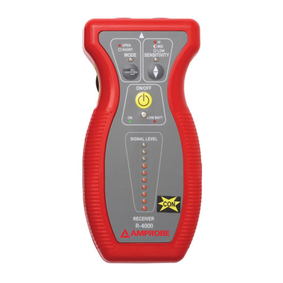
Having confidence in an instrument is an important part of using the instrument. All applications are different and unique. An understanding of the system’s operation could mean the difference between several minutes or several hours on the job. Please read this manual carefully. Take the time to learn how the instrument operates. - Page 7 ➊ ➍ ➋ ➎ ➌ ➏ ➐ R-4000CON Reciever OFF - Low Sensitivity for ➊ LED Indicator: breakers ON - OPEN OFF - SHORT ➎ Sensitivity Control ➋ Mode Control ➏ Power ON/OFF ➌ Sensitivity Control ➐ LED Indicator: Green - Unit ON Thumbwheel Red - Low Battery ➍...
- Page 8 ➊ ➍ ➋ ➌ ➎ ➏ T-4000 Transmitter ➊ Banana Plug Jack ➋ Signal Level Switch ➌ Power ON/OFF ➍ Fuse (inside) Holder ➎ 24 Volt Jack ➏ 9V Battery Compartment...
- Page 9 anywhere between the T-4000 and the power source. (Line side or Upstream)- no signal will be present on wiring on the other side of the transmitter(load side or downstream). For example, a transmitter connected to a circuit breaker will produce no signal on that circuit. It will, however, cause a signal to be generated between that panel and the transformer…and beyond.
-
Page 10: Application Notes
booster (B2024 or B2025) the unit will work in ultra high “U-HI” mode only. Remove the battery booster to return to normal operation.) B2024 Battery Pack 24 Volt Nickel-Cadmium rechargeable cell custom designed for light weight, small size, and durability. Used to boost the output of the T-4000. -
Page 11: Using The T-4000 Transmitter
SHORT Tracing: LED OFF Press SENSITIVITY push button to select the sensitivity level. LOW Sensitivity: LED OFF MEDIUM Sensitivity: LED Blinking HIGH Sensitivity: LED ON Solid Locate the thumbwheel on the left side of the unit Select MEDIUM Sensitivity Level Rotate thumbwheel counterclockwise to decrease sensitivity level Rotate thumbwheel clockwise to increase sensitivity level... -
Page 12: Using The A2202 Clamp-On Transmitter Accessory
Select the signal transmission level (LOW, MID, HIGH) by pressing on the signal level push button. It takes about 2 seconds for the transmission to start after you last hit the push button. (Note: When using the battery booster (B2024 or B2025) the unit will work in ultra high “U-HI”... -
Page 13: Finding Opens
boosted significantly by using the B2024 battery Pack. (Note: When using the battery booster (B2024 or B2025) the unit will work in ultra high “U-HI” mode only. Remove the battery booster to return to normal operation.) One typical application for the A2202 is to access the hot wire at the panel in order to identify the ‘downstream’... -
Page 14: Finding Ground Faults
Select the ‘HIGH’ sensitivity by pressing the SENSITIVITY push button (the LED must be ‘ON’). Starting from the T-4000, trace the conductor. The open will be at the point you begin to lose signal. At that point, select the ‘MID’ sensitivity mode (the LED must be ‘blinking’) in order to pinpoint the exact location of the Open. -
Page 15: Tracing Wires In Conduit
Attach one clip to the faulted wire and the other one to ground. Press the signal level push button and select the appropriate level. If possible, ground all adjacent conductors. The R-4000CON receiver can then be used to trace the wire. The signal should remain relatively constant until you pass the ground fault. -
Page 16: Tracing Energized Wires
If two or more breakers produce the same signal strength indication. Move the receiver away slowly from each of them and watch the indication level. (Refer to Figure 17) Tracing Energized Wires Connect the Alligator Clip Cord set to the T-4000. Make sure the voltage does not exceed the T-4000 rating. -
Page 17: Locating Individual Wires In A Bundle (Energized And Unenergized Lines)
Locating Individual Wires in a Bundle (Energized and Unenergized Lines) Attach alligator clip cord set to the T-4000. Verify that the voltage on the line does not exceed the T-4000 rating. Connect one alligator clip to the wire you wish to identify and the other to a separate ground using the 25’... -
Page 18: Maintenance
Use of the B2024 battery or the B2025 converter is recommended. Set the T-4000 to ‘HIGH’ mode. Set the R-4000CON to ‘SHORT’ mode and ‘LOW’ sensitivity. Trace the conduit. (Refer to Figure 20) Note: When using the battery booster (B2024 or B2025) the unit will work in ultra high “U-HI”... -
Page 19: Troubleshooting
Alligator - Clip Banana Plug Cord Set C2902 Grounding Test Lead 25-FT MTL-G Alligator Clip VRC-320 Carrying Case AT-4000CON CC-AT-4000 Owners Manual www.Amprobe.com Fuse 1000V 0.25A FA 6X46MM FA6X46MM TRoUBLEShooTING Symptom Possible Cause Solution LCD Segments of the 9V battery is low in... -
Page 20: Specifications
SPECIFICATIoNS General Operating Temperature: 0 to 120° F (-18°C to 49°C) Storage temperature: -40° to 150° F (-40° to 66°C) Case Material: ABS Case Size: 0.55” x 0.26” (14x6.7mm) R-4000CoN Receiver Detectors: Electromagnetic Coil Array pick up for short mode. Electrostatic plate pick up for open mode. - Page 21 Weight: 0.32 LB (143.5g) Current Output of the Signal: Low Mode: 11 mA average, 30 mA peak Medium Mode: 12 mA average, 36 mA peak High Mode: 13 mA average, 63 mA peak Fuse: Fast acting 250 mA @ 1000V (6X46mm) P/N: FA6X46MM Signal Output (9V supply): High setting: 0.74 VAC Medium setting: 0.61 VAC...
- Page 22 Output: 24 VDC @350 mah...
- Page 23 Figure 1. Figure 2.
- Page 24 Figure 3. Figure 4. Figure 5.
- Page 25 Figure 6. Figure 7. Figure 8.
- Page 26 In either SHORT or OPEN MODE, the unit is non position sensitive Figure 9. Figure 10.
- Page 27 Figure 11. Figure 12. Figure 13.
- Page 28 Figure 14. Figure 15. Figure 16.
- Page 29 Figure 17. Figure 18.
- Page 30 Figure 19. Figure 20. Figure 21.
- Page 31 Visit www.Amprobe.com for • Catalog • Application notes • Product specifications • User manuals Please Recycle...