
Related Manuals for Planet GSD-1222VHP


Summary of Contents for Planet GSD-1222VHP
- Page 1 8-/16-/24-Port 10/100/1000T 802.3at PoE+ Gigabit SFP Ethernet Switch with Smart LCD GSD-1222VHP/GSW-1820VHP/GSW-2620VHP User’s Manual...
- Page 2 Copyright Copyright © 2018 by PLANET Technology Corp. All rights reserved. No part of this publication may be reproduced, transmitted, transcribed, stored in a retrieval system, or translated into any language or computer language, in any form or by any means, electronic, mechanical, magnetic, optical, chemical, manual or otherwise, without the prior written permission of PLANET.
- Page 3 Do not dispose of WEEE as unsorted municipal waste; WEEE should be collected separately. Revision PLANET 8-/16-/24-Port 10/100/1000T 802.3at PoE+ Gigabit SFP Ethernet Switch with Smart LCD User's Manual Models: GSD-1222VHP, GSW-1820VHP, GSW-2620VHP Revision: 3.0 (Dec., 2018)
-
Page 4: Table Of Contents
Table of Contents 1. Introduction ....................5 1.1 Package Contents ................5 1.2 Product Description ................6 1.3 Features ....................10 1.4 Specifications ..................12 2. Hardware Description .................15 2.1 Front Panel ..................15 2.1.1 LCD Monitor Indicators ..............16 2.1.2 LED Indicators ................17 2.2 Rear Panel ..................19 2.3 LCD Management ................20 2.3.1... -
Page 5: Introduction
1. Introduction Thank you for purchasing PLANET 8/16/24-Port 10/100/1000T 802.3at PoE+ Gigabit SFP Ethernet Switch series, GSD-1222VHP, GSW-1820VHP and GSW-2620VHP. The descriptions of these models are shown below: 8-Port 10/100/1000T 802.3at PoE + 2-Port Gigabit SFP + 2-Port GSD-1222VHP Gigabit TP Ethernet Switch 16-Port 10/100/1000T 802.3at PoE + 2-Port Gigabit SFP Ethernet... -
Page 6: Product Description
1.2 Product Description Ideal High-performance Integration Solution for Secure IP Surveillance Infrastructure Particularly designed for the growing popular IP surveillance applications, PLANET GSD/GSW 802.3at PoE+ Switch series is positioned as a surveillance switch with the central power management and IP camera monitoring. - Page 7 Just “Plug and Watch” for a Quick Solution The GSD/GSW 802.3at PoE+ Switch series is an ideal Plug and Watch Power over Ethernet solution which provides quick installation, real-time PoE work status monitoring and immediate troubleshooting through its unique LCD display to improve work efficiency and quality without any PC or software required.
- Page 8 < E n t e r > : C o n f i r m < B a c k > : R e t u r n System 16-Port 10/100/1000T 802.3at PoE GSW-1820VHP Menu (5 sec) PLANET 802.3af/at PoE Switch 2-Port Gigabit SFP Ethernet Switch Model: FGSW-2622VHP HW ver: V2.0 Enter SW ver: V3.01 www.planet.com.tw...
- Page 9 Standard, VLAN and Extend Operation Modes Offered The GSD/GSW 802.3at PoE+ Switch series provides Standard, VLAN and Extend operation modes. The GSD/GSW 802.3at PoE+ Switch series operates as a normal IEEE 802.af/at PoE Switch in the Standard operation mode. The VLAN operation mode features the port-based VLAN function that can help to prevent the IP camera’s multicast or broadcast storm from influencing each other.
-
Page 10: Features
Ethernet device without requiring special straight-through or crossover cables. 1.3 Features Physical Port GSD-1222VHP „ 8-port 10/100/1000BASE-T Gigabit RJ45 copper „ 2 1000BASE-X mini-GBIC SFP interfaces „ 2 10/100/1000BASE-T TP interfaces GSW-1820VHP „... - Page 11 „ Up to 8/16/24 ports of IEEE 802.3af/at devices powered „ Supports PoE Power up to 32 watts for each PoE port „ Each port supports 52V DC power to PoE powered device (GSD-1222VHP) „ 120-watt PoE budget (GSD-1222VHP) „ Each port supports 54V DC power to PoE powered device (GSW-1820VHP/ GSW-2620VHP) „...
-
Page 12: Specifications
„ Supports Energy-Efficient Ethernet (EEE) function (IEEE 802.3az) „ Supports contact discharge of ±6KV DC and air discharge of ±8KV DC for Ethernet ESD protection „ Supports ±6KV surge immunity 1.4 Specifications Model GSD-1222VHP GSW-1820VHP GSW-2620VHP Hardware Specifications 802.3af/at PoE Injector Port... - Page 13 System: Power (Green) 10/100/1000BASE-T RJ45 Interfaces: 10/100Mbps LNK/ACT (Red) 1000Mbps LNK/ACT (Green) PoE-in-Use (Amber) LED Indicators 1000BASE-X SFP Interfaces: 10/100Mbps LNK/ 1000BASE-X SFP Interfaces: ACT (Red) LNK/ACT (Green) 1000Mbps LNK/ ACT (Green) LCD Monitor (W x D) 40.6 x 30.5 mm, 2-inch Buttons Menu, Enter, Back, Up and Down Dimensions...
- Page 14 Max. Number of Class 2 PDs Max. Number of Class 3 PDs Max. Number of Class 4 PDs Standards Conformance Regulatory FCC Part 15 Class A, CE Compliance IEEE 802.3 10BASE-T IEEE 802.3u 100BASE-TX IEEE 802.3ab Gigabit 1000BASE-T Standards IEEE 802.3z Gigabit SX/LX Compliance IEEE 802.3x Flow Control and Back Pressure IEEE 802.3af Power over Ethernet...
-
Page 15: Hardware Description
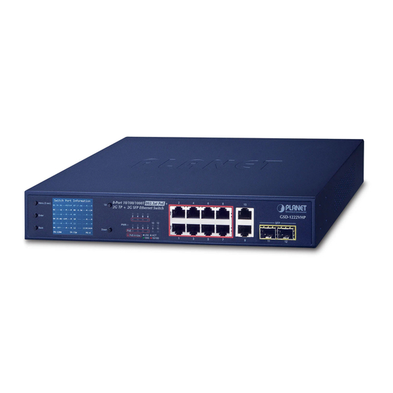
- ---M ---M 223M 246M Back Down PB:120W TP:72W PD:4 PoE-in-Use 1000 10/100 Figure 2-1: GSD-1222VHP Switch Front Panel Switch Port Information 16-Port 10/100/1000T 802.3at PoE GSW-1820VHP Menu (5 sec) 30.3 W ---M -33M ---- W ---M ---M 2-Port Gigabit SFP Ethernet Switch... -
Page 16: Lcd Monitor Indicators
„ Smart LCD The Smart LCD that is located on the front panel of the GSD-1222VHP, GSW- 1820VHP, GSW-2620VHP 802.3at PoE+ Switch provides “PoE Manage- ment and Status”, “Switch Mode: Standard, VLAN, Extend”, “Budget and Bandwidth Control”, “Screen Saver”, “Fan Control”, and “Factory Default”. -
Page 17: Led Indicators
„ The detailed Smart LCD description of each item is shown below: Parameters Description 30.3W It means the output power port of the PoE switch. (example) It means the port is overloaded corresponding to the PSE, and the port stops powering. It means the port corresponding to the PSE is lightly loaded and the port stops powering (When the current on the network is less than 7.5mA, the PSE thinks the PD has been dialed out and the... - Page 18 Indicates that the Switch is actively sending or receiving Blinks data over that port. 1000 Green Lights Indicates the port is successfully established at 1000Mbps. „ 1000Mbps TP Slot (GSD-1222VHP) Color Function Indicates the link through that port is successfully Lights established at 1000Mbps.
-
Page 19: Rear Panel
The rear panel of the 802.3at PoE+ Switch has an AC power socket (100 to 240V AC, 50-60Hz, 2.5/5A). 100-240V AC 50/60Hz, 2.5A Figure 2-4: GSD-1222VHP Switch Rear Panel 100~240V AC 50/60Hz, 5A max. Figure 2-5: GSW-1820VHP/GSW-2620VHP Switch Rear Panel „ AC Power Receptacle For compatibility with electrical outlet standard in most areas of the world, the 802.3at PoE+ Switch’s power supply automatically adjusts to line power in the... -
Page 20: Lcd Management
2.3 LCD Management The operation of the 5 buttons (Menu, Enter, Back, Up and Down) on the panel: Switch Port Information Menu (5 sec) 30.3 W ---M 867M ---- W ---M ---M ---- W ---M ---M -8.3 W ---M -<1M ---M ---M ---- W ---M ---M... -
Page 21: Switch Mode
(default) all PoE ports operate at 10/100/1000Mbps auto-negotiation. This mode makes the This mode makes the This mode makes the GSD-1222VHP operate as GSW-1820VHP operate as GSW-2620VHP operate as a VLAN isolation switch a VLAN isolation switch a VLAN isolation switch 1. - Page 22 Standard Mode (default) > Standard PoE IP Camera VLAN Extend Power GSW-1820VHP 100 meters (328 feet) 1000BASE-T UTP with PoE VLAN Isolation Mode IP Camera Ports 1 to 16 Ports 17 and 18 for uplink IP Camera Access Denied 1000 Ports 1~16 Access Permitted Standard >...
-
Page 23: Budget Control
VLAN Isolation Feature The 802.3at PoE+ Switch has one feature called VLAN function. When switching the mode to the “VLAN” position, port 1 to port 8/16/24 wouldn’t able to communicate with each other. VLAN 1: P1 P17 P18 VLAN 2: P2 P17 P18 Standard >... -
Page 24: Pse Port Priority
2.3.3 PSE Port Priority The Priority represents PoE ports priority. There are three levels of power priority named Low, High and Critical. The priority is used in case the total power consumption is over the total power budget. In this case the port with the lowest priority will be turned off, and offer power for the port of higher priority. -
Page 25: Pd Type
2.3.5 PD Type Changing the PoE power-up mode can let non-standard PDs pass the procedures of PoE power delivery process. This way, the switch can supply power to non- standard PDs. The GSD/GSW 802.3at PoE+ Switch series can set the PoE power- up mode to be in Enhance mode, Standard mode or Legacy mode by the user interface. -
Page 26: Alive Check
2.3.6 Alive Check The GSD/GSW 802.3at PoE+ Switch series can be configured to monitor connected PD’s status in real time via traffic detection. Once there is no traffic at interval time, the GSD/GSW 802.3at PoE+ Switch series is going to restart PoE port power, and bring the PD back to work. -
Page 27: Bandwidth Detection
The PD Alive Check is not a defining standard, so the PoE device on the market doesn’t report reboots done information to the PoE Switch. So user has to make sure how long it takes for the PD to finish booting, and then set the time value related column. -
Page 28: Fan Control
2.3.8 Fan Control Fan control is to achieve the set power with intelligent operation. There are four levels of budget control, namely Always ON, 20% PB (default), 40% PB and 60% PB. 2.3.9 Screen Saver There are four levels of budget control, namely Always ON, 10min (default), 20min and 30min. -
Page 29: Language
2.3.10 Language There are two languages, namely English and Chinese. 2.3.11 Default Setting Press “Yes” to reset to default. 2.3.12 System Show the system information. -
Page 30: Hardware Installation
3. Hardware Installation Start up Please refer to the following for your cabling: 10/100/1000BASE-T 10/100/1000BASE-T ports come with Auto-Negotiation capability. They automatically support 1000BASE-T, 100BASE-TX and 10BASE-T networks. Users only need to plug a working network device into one of the 10/100/1000BASE-T ports, and then turn on the 802.3at PoE+ Switch. -
Page 31: Desktop Installation
3.1 Desktop Installation To install the 802.3at PoE+ Switch on desktop, simply follow the following steps: Step 1: Attach the rubber feet to the recessed areas on the bottom of the 802.3at PoE+ Ethernet Switch, as shown in Figure 3-1. Men u (5 sec) Ente r... -
Page 32: Rack Mounting
3.2 Rack Mounting To install the 802.3at PoE+ Switch in a 19-inch standard rack, follow the instructions described below. Step 1: Place your 802.3at PoE+ Switch on a hard flat surface, with the front panel positioned towards your front side. Step 2: Attach a rack-mount bracket to each side of the 802.3at PoE+ Switch with supplied screws attached to the package. -
Page 33: Installing The Sfp Transceiver
Figure 3-4: Plugging in the SFP Transceiver „ Approved PLANET SFP Transceivers PLANET 802.3at PoE+ Switch supports both single mode and multi-mode SFP transceivers. The following list of approved PLANET SFP transceivers is correct at the time of publication: Gigabit SFP Transceiver Modules „... - Page 34 It is recommended to use PLANET SFP on the 802.3at PoE+ Switch. If you insert an SFP transceiver that is not supported, the 802.3at PoE+ Switch will not recognize it. Note 1. Before we connect the 802.3at PoE+ Switch to the other network device, we have to make sure both sides of the SFP transceivers are with the same media type, for example, 1000BASE-SX to 1000BASE-SX;...
-
Page 35: Product Applications
Never pull out the module without lifting up the lever of the module and turning it to a horizontal position. Directly pulling out the module could damage the module and the SFP module slot of Note the 802.3at PoE+ Switch. 3.4 Product Applications Department/Workgroup PoE Switch: Providing 8/16/24 PoE in-line power interfaces, the 802.3at PoE+ Switch can... -
Page 36: Power Over Ethernet Powered Devices
3.5 Power over Ethernet Powered Devices Voice over IP Phones As many as PoE VoIP phones, ATAs and other Ethernet/ non-Ethernet end-devices can be installed, but UPS is needed for uninterrupted power system and power control 3~5 watts system. Wireless LAN Access Points Access points can readily be installed in museums, sightseeing sites, airports, hotels, campuses, factories and warehouses. -
Page 37: Power Over Ethernet Overview
4. Power over Ethernet Overview What is PoE? PoE is an abbreviation of Power over Ethernet. The PoE technology means a system safely transmits both power and data on Ethernet UTP cable. The IEEE standard for PoE technology requires Category 5 cable or higher for high power PoE levels, but can operate with Cat3 cable for low power levels. - Page 38 intermediary device between a non-PoE capable switch and a PoE device, it is called a mid-span. An external PoE injector is a mid-span device. Powered Device A powered device (PD) is a device powered by a PSE and thus consumes energy. Examples include wireless access points, IP phones, and IP cameras.
- Page 39 The data pairs are used. Since Ethernet pairs are transformers coupled at each end, it is possible to apply DC power to the center tap of the isolated transformer without upsetting the data transfer. In this mode of operation, the pair on pins 3 and 6 and the pair on pins 1 and 2 can be of either polarity.
-
Page 40: Troubleshooting
5. Troubleshooting This chapter contains information to help you solve issues. If the 802.3at PoE+ Switch is not functioning properly, make sure the 802.3at PoE+ Switch was set up according to instructions in this manual. The Link LED is not lit. Solution: Check the cable connection and also try to swap one new cable. -
Page 41: Appendix A Networking Connection
Appendix A Networking Connection A.1 Switch's Data RJ45 Pin Assignments - 1000Mbps, 1000BASE-T PIN NO MDI-X BI_DA+ BI_DB+ BI_DA- BI_DB- BI_DB+ BI_DA+ BI_DC+ BI_DD+ BI_DC- BI_DD- BI_DB- BI_DA- BI_DD+ BI_DC+ BI_DD- BI_DC- Implicit implementation of the crossover function within a twisted-pair cable, or at a wiring panel, while not expressly forbidden, is beyond the scope of this standard. - Page 42 The standard cable, RJ45 pin assignment The standard RJ45 receptacle/connector There are 8 wires on a standard UTP/STP cable and each wire is color-coded. The following shows the pin allocation and color of straight-through cable and crossover cable connection: Straight Cable SIDE 1 SIDE 2 1 = White/Orange...
- Page 43 : GSD-1222VHP * Produced by: Manufacturer‘s Name : Planet Technology Corp. Manufacturer‘s Address : 10F., No.96, Minquan Rd., Xindian Dist., New Taipei City 231, Taiwan is herewith confirmed to comply with the requirements set out in the Council Directive on the Approximation of the Laws of the Member States relating to Electromagnetic Compatibility Directive 2014/30/EU.
- Page 44 : GSW-1820VHP, GSW-2620VHP * Produced by: Manufacturer‘s Name : Planet Technology Corp. Manufacturer‘s Address : 10F., No.96, Minquan Rd., Xindian Dist., New Taipei City 231, Taiwan is herewith confirmed to comply with the requirements set out in the Council Directive on the Approximation of the Laws of the Member States relating to Electromagnetic Compatibility Directive 2014/30/EU.