
Related Manuals for Broan Glacier BCSD Series


Summary of Contents for Broan Glacier BCSD Series
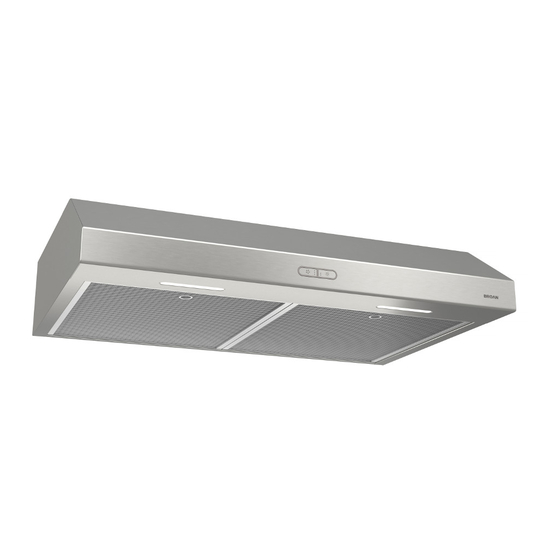
- Page 1 WWW.BROAN-NUTONE.COM RANGE HOOD Series: BCSD INSTALLATION, USE AND CARE MANUAL Serial number: 99045652-102H...
-
Page 2: Table Of Contents
Safety ....... . . 3-4 Operation ....... 5 Cleaning and Maintenance . - Page 3 READ AND SAVE THESE INSTRUCTIONS Intended for domestic cooking only INSTALLER: LEAVE THIS MANUAL WITH HOMEOWNER. Register your range hood online at www.broan-nutone.com WARNING TO REDUCE THE RISK OF FIRE, ELECTRIC SHOCK, OR INJURY TO PERSONS, OBSERVE THE FOLLOWING: • Use this unit only in the manner intended by the manufacturer. If you have questions, contact the manufacturer at the address or telephone number listed in the warranty.
- Page 4 WARNING TO REDUCE THE RISK OF A RANGE TOP GREASE FIRE: a) Never leave surface units unattended at high settings. Boilovers cause smoking and greasy spillovers that may ignite. Heat oils slowly on low or medium settings. b) Always turn hood ON when cooking at high heat or when flambeing food (i.e.: Crêpes Suzette, Cherries Jubilee, Peppercorn Beef Flambé).
-
Page 5: Operation
Operation Always turn your hood on before you begin cooking to establish an air flow in the kitchen. Let the blower run for a few minutes to clear the air after you turn off the range. This will help keep the whole kitchen cleaner and fresher. Operate the hood as follows: FAN SWITCH LIGHT SWITCH... -
Page 6: Cleaning And Maintenance
Cleaning and Maintenance Proper maintenance of the Range Hood will assure proper performance of the unit. MOTOR The motor is permanently lubricated and never needs oiling. If the motor bearings make excessive or unusual noise, replace the motor with the exact service motor. The fan blade should also be replaced. -
Page 7: Installation
For ADA compliance installation guidelines, please type the model number into our website. Recommended Tools and Accessories for Installation • Measuring tape • Phillips screwdriver no. 2 • Flat blade screwdriver (to open knockout holes) • Drill, 1/8” drill bit and 1½” hole saw (to mark holes for ducting and cut electrical access hole) •... -
Page 8: Contents
Contents Before proceeding to the installation, check the contents of the box. If items are missing or damaged, contact the manufacturer. Make sure that the following items are included: IND INSIDE OF HOOD (1) 3¼” 10” (1) 7” R OUND (2) G REASE ILTERS... -
Page 9: Prepare The Hood
Prepare the Hood 1 ] If present, remove all protective polyfilm from the hood and/or parts. 2 ] Using the tab, remove the grease filters from the hood by pushing down and tilting filters out. 3 ] Remove both screws holding damper assembly to hood. Remove parts bag included with the hood (captured behind the damper assembly).Remove damper assembly from inside the hood and keep the screws for further use. - Page 10 5 ] Remove 7” Round Duct Plate from top/back of hood (see illustration below). 7” ROUND DUCT PLATE 2 SCREWS 6 ] Remove Electrical Power Cable Knockout from top (vertical exhaust) or back (horizontal exhaust) of hood. Install an appropriate strain relief, 1/2” diameter (not included). ELECTRICAL POWER CABLE KNOCKOUT...
- Page 11 DUCTED INSTALLATION ONLY 8 ] Remove 3¼” x 10” vertical, 3¼” x 10” horizontal, or 7-inch round knockout plate as appropriate for your ducting method (see F 1 A and 1 B). IGURES IGURE IGURE 7” ROUND KNOCKOUT PLATE ( ALSO REMOVE VERTICAL KNOCKOUT PLATE 3¼”...
-
Page 12: Prepare The Hood Location
Prepare the Hood Location NOTE: Before starting installation, read all the steps of these instructions. Use the illustration below to identify your kitchen cabinet type. FRAMED CABINET FRAMELESS CABINET This manual covers 2 kinds of installation: the standard (without EZ1 brackets) and the EZ1 one-person installation system (using included template and brackets). - Page 13 4 ] Drill a 1/8” dia. pilot hole for house wiring, at A location on template. 5 ] Use a sharp pencil or 1/8” drill bit to mark the locations for the appropriate duct access holes (16 locations for 7” round duct, or 4 corner locations for rectangular duct). Remove the template.
- Page 14 FRAMELESS CABINET Refer to the marking on brackets to determine the correct installation side and orientation. 7/64” Align the corresponding bracket to the cabinet side, while placing rear end of bracket against the wall. Draw a line on the outer edge of the bracket (as shown). ...
-
Page 15: Install The Hood (Ez1 Bracket)
Install the Hood (EZ1 Bracket) OTE: The following procedure applies to both framed or frameless cabinet installations. 1 ] Run house power cable between service panel and hood location. 2 ] There are 2 pairs of recessed holes on each side of the top of the hood (on rear: A and B, on front C and D on illustration below);... - Page 16 7 ] For framed cabinet, secure the hood to the EZ1 brackets using 4 no. 8-18 x 1/2” metal screws (included in parts bag). Insert 2 screws per side, in the slots (as shown in insets on illustration below). 8 ] For frameless cabinet, secure the hood to the cabinet using 4 no. 8 x 5/8” round head wood screws (included in parts bag).
-
Page 17: Standard Installation
Standard Installation (without EZ1 Brackets) 1 ] Use the proper diagram below for placement of ductwork and electrical cutout in cabinet or wall. For a non-ducted installation, DO NOT cut a duct access hole, only cut the hole for electrical wiring. 3¼"... -
Page 18: Install The Hood (Standard Installation)
Install the Hood (Standard Installation) 1 ] Run house power cable between service panel and hood location. Run the house power cable into the hood through the strain relief previously installed in step 6 on page 10. 2 ] Hang hood from (4) mounting screws previously installed. Slide hood back towards wall until mounting screw heads are engaged in narrow end of keyhole slots in top of hood. -
Page 19: Connect The Wiring
Connect the Wiring WARNING Risk of electric shock. Electrical wiring must be done by qualifi ed personnel in accordance with all applicable codes and standards. Before connecting wires, switch power off at service panel and lock service disconnecting means to prevent power from being switched on accidentally. -
Page 20: Install The Light Bulbs
Install the Light Bulbs Install two shielded Halogen Bulbs (120 V, 50 W max., MR16 or PAR16 with GU10 base), not included. WARNING Do not touch lamps during or soon after operation. Burns may occur. In order to prevent the risk of personal injury, only install shielded halogen lamps. Also, never install a cool beam, a dichroic lamp, a lamp not suitable for use in recessed luminaires or identified for use in enclosed fixtures. - Page 22 EPAIRS In order to ensure your unit remains in good working condition, you must use Broan-NuTone LLC genuine replacement parts only. Broan-NuTone LLC genuine replacement parts are specially designed for each unit and are manufactured to comply with all the applicable certification standards and maintain a high standard of safety.
- Page 23 EPAIRS In order to ensure your unit remains in good working condition, you must use Broan-NuTone LLC genuine replacement parts only. Broan-NuTone LLC genuine replacement parts are specially designed for each unit and are manufactured to comply with all the applicable certification standards and maintain a high standard of safety.
- Page 24 EPAIRS In order to ensure your unit remains in good working condition, you must use Broan-NuTone LLC genuine replacement parts only. Broan-NuTone LLC genuine replacement parts are specially designed for each unit and are manufactured to comply with all the applicable certification standards and maintain a high standard of safety.
- Page 25 EPAIRS In order to ensure your unit remains in good working condition, you must use Broan-NuTone LLC genuine replacement parts only. Broan-NuTone LLC genuine replacement parts are specially designed for each unit and are manufactured to comply with all the applicable certification standards and maintain a high standard of safety.
-
Page 26: Warranty
Limited Warranty Warranty Period and Exclusions: Broan-NuTone LLC (the “Company”) warrants to the original consumer purchaser of its product (“you”) that the product (the “Product”) will be free from material defects in the Product or its workmanship for a period of one (1) year from the date of original purchase (or such longer period as may be required by applicable law). - Page 27 WWW.BROAN-NUTONE.COM CAMPANA DE COCINA Series: BCSD MANUAL DE INSTALACIÓN, UTILIZACIÓN Y CUIDADO Número de serie: 99045652-102H...
- Page 28 Seguridad ......3-4 Funcionamiento ......5 Limpieza y mantenimiento .
- Page 29 LEA ESTAS INSTRUCCIONNES Y GUÁRDELAS Exclusivamente para cocinas domésticas INSTALADOR: ENTREGUE ESTE MANUAL AL PROPIETARIO. Registre su campana de cocina en línea en www.broan-nutone.com ADVERTENCIA PARA REDUCIR EL RIESGO DE INCENDIO, DESCARGA ELÉCTRICA O LESIÓN CORPORAL, RESPETE LAS SIGUIENTES INDICACIONE: •...
- Page 30 ADVERTENCIA PARA REDUCIR EL RIESGO DE QUE ARDA LA GRASA EN LA PARTE SUPERIOR DE LA COCINA: No deje nunca recipientes de cocina a fuego vivo sin vigilancia. Los desbordamientos producen humo y derrames grasientos que pueden inflamarse. Caliente el aceite despacio, a fuego lento o mediano. Ponga en marcha siempre la campana extractora al cocinar a temperaturas elevadas o al cocinar alimentos flameados (crepas Suzette, cerezas jubilee, res con pimienta flambeada).
-
Page 31: Funcionamiento
Funcionamiento Ponga la campana en marcha siempre antes de empezar a cocinar para crear una corriente de aire en la cocina. Deje funcionar el ventilador impelente varios minutos para limpiar el aire cuando ya haya apagado la cocina. De este modo, la cocina estará más limpia y despejada. La campana funciona así: INTERRUPTOR INTERRUPTOR... -
Page 32: Limpieza Y Mantenimiento
Limpieza y mantenimiento El mantenimiento adecuado de la campana permitirá que funcione correctamente. MOTOR El motor está lubricado permanentemente y no necesita engrase nunca. Si los rodamientos del motor hacen un ruido excesivo o no habitual, sustituya el motor por otro idéntico. También se debería sustituir la hélice. -
Page 33: Instalación
Para las directrices de instalación conforme a la ADA, por favor, ingrese su número de modelo en nuestro sitio web. Herramientas y accesorios recomendados para la instalación • Cinta métrica • Destornillador Phillips n.° 2 • Destornillador de punta plana (para abrir los orificios punzonados) •... - Page 34 Contenido Antes empezar la instalación, verifique el contenido de la caja. Si faltan elementos o hay elementos dañados, póngase en contacto con el fabricante. Compruebe que estén en la caja los siguientes elementos: E ENCUENTRA DENTRO DE LA CAMPANA (1) C (1) C ONJUNTO DE LA ONECTOR...
-
Page 35: Prepare La Campana
Prepare la campana 1 ] De haberla, retire de la campana y de todas las piezas la película protectora. 2 ] Use la pestaña para retirar de la campana el filtro de grasa empujando hacia abajo e inclinando el filtro hacia fuera. 3 ] Retire ambos tornillos que sujetan el conjunto de la clapeta a la campana. - Page 36 5 ] Retire la placa para conducto redondo de 7” de la parte superior trasera de la campana (véase la ilustración de abajo. PLACA PARA CONDUCTO REDONDO DE 7” 2 TORNILLOS 6 ] Retire la parte punzonada para el cable de alimentación eléctrica desde la parte superior (salida vertical) o desde la parte trasera (salida horizontal) de la campana.
- Page 37 INSTALACIÓN CON CONDUCTOS ÚNICAMENTE 8 ] Retire la placa punzonada vertical de 3¼” x 10” , la placa punzonada horizontal de 3¼” x 10” o la placa punzonada redonda de 7 pulgadas, según el modo de evacuación elegido (véanse las Figuras 1 A y 1 B). IGURA IGURA PLACA PUNZONADA...
-
Page 38: Prepare La Ubicación De La Campana
Prepare la ubicación de la campana NOTA: antes de empezar la instalación, lea todas las etapas de estas instrucciones. Use la ilustración de abajo para reconocer su tipo de armario de cocina. ARMARIO CON ARMAZÓN ARMARIO SIN ARMAZÓN Este manual cubre 2 tipos de instalación: la normal (sin soportes EZ1) y la instalación EZ1 por una persona (usando la plantilla y los soporte provistos). - Page 39 4 ] Taladre un orificio piloto de 1/8” de diámetro para el cableado de la vivienda, en el punto A de la plantilla. 5 ] Use un lápiz afilado o una broca de 1/8” para marcar los puntos para los orificios de acceso de los conductos (16 puntos para un conducto redondo de 7”...
- Page 40 ARMARIO SIN ARMAZÓN Consulte las marcas de los soporte para establecer el lado y la orientación correctos de la instalación (marcas en ingles solamente: front = frente, left = izquierda, lean on rear wall = appoyar contra la pared de atrás). 7/64”...
-
Page 41: Instale La Campana (Soporte Ez1)
Instale la campana (Soporte EZ1) OTA: El procedimiento siguiente se aplica a las instalaciones en armarios con armazón y sin armazón. 1 ] Lleve el cable de alimentación de la vivienda del tablero de servicio al lugar de la campana. 2 ] Hay 2 pares de orificios rebajados en cada lado de la parte superior de la campana (en la parte trasera: A y B, en la parte delantera C y D en la ilustración de abajo);... - Page 42 7 ] En los armarios con armazón, sujete la campana a los soportes EZ1 por medio de los (4) tornillos para metal n.° 8-18 x 1/2” (vienen en la bolsa de piezas). Introduzca (2) tornillos en cada lado, en las ranuras (como se ve en los detalles de la ilustración de abajo). 8 ] En los armarios sin armazón, sujete la campana al armario por medio de los (4) tornillos de cabeza redonda para madera n.°...
-
Page 43: Instalación Normal
Instalación normal (sin soportes EZ1) 1 ] Use el diagrama adecuado de abajo para colocar los conductos y la alimentación eléctrica en el armario o en la pared. Para una instalación sin conductos, NO corte el orificio de acceso al conducto; corte sólo el orificio para el cableado eléctrico. TORNILLOS DE MONTAJE EVACUACIÓN VERTICAL DE LA CAMPANA (4) -
Page 44: Instale La Campana (Instalación Normal)
Instale la campana (Instalación normal) 1 ] Lleve el cable de alimentación de la vivienda del tablero de servicio al lugar de la campana. Lleve el cable de alimentación de la vivienda a la campana a través de la descarga de presión instalada previamente en la etapa 6 en la página 10. -
Page 45: Conecte El Cableado
Conecte el cableado ADVERTENCIA Riesgo de descarga eléctrica. El cableado eléctrico debe hacerlo personal cualifi cado de acuerdo con los códigos y normas aplicables. Antes de conectar los hilos, corte la corriente en el tablero de servicio y bloquee éste para evitar que se ponga en marcha accidentalmente. HILO DE TIERRA DEL MOTOR... -
Page 46: Instale Las Bombillas
Instale las bombillas Instale dos bombillas halógenas con pantalla (120 V, 50 W máx., MR16 o PAR16 con base GU10) (no incluido). ADVERTENCIA No toque las bombillas mientras funcionen o poco después de que hayan dejado de funcionar. Podría quemarse. Para prevenir riesgos de daños personales, instale sólo bombillas halógenas con pantalla. - Page 47 21 21 21 21...
- Page 48 Para que el aparato esté en buenas condiciones, use sólo repuestos genuinos Broan-NuTone LLC. Los repuestos genuinos Broan-NuTone LLC están diseñados especialmente para cada unidad y han sido fabricados para responder a las normas de certificación aplicables y mantener un alto nivel de seguridad. Los repuestos de otros fabricantes pueden dañar seriamente el aparato y reducir drásticamente su nivel de rendimiento, lo cual podría causar una falla prematura.
- Page 49 Para que el aparato esté en buenas condiciones, use sólo repuestos genuinos Broan-NuTone LLC. Los repuestos genuinos Broan-NuTone LLC están diseñados especialmente para cada unidad y han sido fabricados para responder a las normas de certificación aplicables y mantener un alto nivel de seguridad. Los repuestos de otros fabricantes pueden dañar seriamente el aparato y reducir 23 23 23 23 drásticamente su nivel de rendimiento, lo cual podría causar una falla prematura.
- Page 50 Para que el aparato esté en buenas condiciones, use sólo repuestos genuinos Broan-NuTone LLC. Los repuestos genuinos Broan-NuTone LLC están diseñados especialmente para cada unidad y han sido fabricados para responder a las normas de certificación 24 24 24 24 aplicables y mantener un alto nivel de seguridad.
- Page 51 Para que el aparato esté en buenas condiciones, use sólo repuestos genuinos Broan-NuTone LLC. Los repuestos genuinos Broan-NuTone LLC están diseñados especialmente para cada unidad y han sido fabricados para responder a las normas de certificación aplicables y mantener un alto nivel de seguridad. Los repuestos de otros fabricantes pueden dañar seriamente el aparato y reducir drásticamente su nivel de rendimiento, lo cual podría causar una falla prematura.
-
Page 52: Garantía
Garantía limitada Periodo y exclusiones de la garantía: Broan-NuTone LLC (la “Compañía”) garantiza al consumidor comprador original de su producto (“usted”) que el producto (el “Producto”) estará libre de defectos en materiales o en mano de obra, por un periodo de un (1) año a partir de la fecha de compra original (o por un periodo mayor según sea requerido por la legislación aplicable).