Table of Contents
Advertisement
Quick Links
Advertisement
Table of Contents

Related Manuals for Agilent Technologies 54810A


Summary of Contents for Agilent Technologies 54810A
- Page 1 User’s Quick Start Guide Publication number 54810-97045 January 2000 For Safety information, Warranties, and Regulatory information, see the pages at the end of this manual. © Copyright Agilent Technologies 1997-2000 All Rights Reserved Infiniium Oscilloscopes...
- Page 2 GPIB interface card, see the Infiniium Oscilloscopes Programmer’s Reference. • For information on testing and servicing the oscilloscope, see either the Infiniium Service Guide for Models 54810A/15A/20A/25A Oscilloscopes or the Infiniium Service Guide for the Model 54835A and 54845A Oscilloscope.
-
Page 3: Table Of Contents
Contents Setting Up the Oscilloscope To inspect package contents 1-3 To inspect options and accessories 1-5 To connect power 1-8 To connect the mouse or other pointing device 1-11 To attach the optional trackball 1-12 To connect the keyboard 1-17 To connect to the LAN card 1-18 To connect oscilloscope probes 1-19 To connect a printer 1-22... - Page 4 Contents To turn a channel on or off 3-40 To adjust the vertical offset 3-41 To adjust vertical scaling 3-43 To access the channel setup 3-44 To set the horizontal reference point 3-45 To adjust sweep speed 3-46 To adjust horizontal position 3-47 To access the horizontal setup 3-48 To zoom on a section of the waveform 3-49 To move the markers using the graphical interface 3-51...
-
Page 5: Setting Up The Oscilloscope
Setting Up the Oscilloscope... - Page 6 Setting Up the Oscilloscope This chapter shows you how to set up your Infiniium oscilloscope, connect power and accessories, and verify general operation.
-
Page 7: To Inspect Package Contents
Technologies Sales Office. • If the shipping container is damaged, or the cushioning materials show signs of stress, notify the carrier and your Agilent Technologies Sales Office. Keep the shipping materials for the carrier’s inspection. The Agilent Technologies Sales Office will arrange for repair or replacement at Agilent’s option without... - Page 8 Figure 1-1 Infiniium Oscilloscope with Accessory Pouch Keyboard 1160A or 1161A Probe PS/2 Mouse and Mouse Pad 54810A/15A/20A/25A Oscilloscopes Service Guide or 54835A and 54845A Oscilloscope Service Guide Infiniium Oscilloscopes Programmer’s Reference Infiniium Oscilloscopes User’s Quick Start Guide Infiniium Oscilloscopes Programmer’s Quick Reference...
-
Page 9: To Inspect Options And Accessories
Agilent Technologies Sales Office. Some of the options available for the Infiniium Oscilloscopes are listed in table 1-1. Contact your Agilent Technologies Sales Office for a complete list of options, or look in the built-in information system under the Accessories List. - Page 10 Setting Up the Oscilloscope To inspect options and accessories Option Description Spanish User’s Quick Start Guide French User’s Quick Start Guide Japanese User’s Quick Start Guide Italian User’s Quick Start Guide Add 1 Touchpad pointing device (E2612A) Add 1 Clip-on trackball pointing device (E2611A) 3 years calibration service 3 years return standards comp calibration service 5 years return repair service (additional 2 years)
- Page 11 Setting Up the Oscilloscope To inspect options and accessories Agilent Model Description Number 1182A Testmobile 1250-2427 PC Board Mini-Probe Socket (horizontal mount) 1250-2428 PC Board Mini-Probe Socket (vertical mount) 34398A RS-232-C printer cable 34399A RS-232-C Adapter kit Ω Ω 54006A 6 GHz probe, 10:1 (500 ) or 20:1 (1 k ), .25 pf...
-
Page 12: To Connect Power
1 Position the oscilloscope where it will have sufficient clearance for airflow around the top, back, and sides. Figure 1-2 Minimum 38.1 mm Minimum 0 mm Minimum 15.9 mm Minimum 15.9 mm both sides Airflow requirements 54810A-25A 125 cfm 54835A-45A 250 cfm Positioning the Infiniium Oscilloscope with Sufficient Clearance... - Page 13 The oscilloscope power supply automatically adjusts for line input voltages in the range 100 to 240 VAC. Therefore, you do not need to adjust an input line voltage setting. The line cord provided is matched by Agilent Technologies to the country of origin of the order.
- Page 14 Setting Up the Oscilloscope To connect power Table 1-3 Power Cords Plug Type Cable Part Plug Description Length Color Country (in/cm) 250V 8120-1351 Straight *BS1363A 90/228 Gray United Kingdom, Cyprus, Nigeria, 8120-1703 90° 90/228 Mint Gray Zimbabwe, Singapore 250V 8120-1369 Straight *NZSS198/ASC 79/200 Gray...
-
Page 15: To Connect The Mouse Or Other Pointing Device
Setting Up the Oscilloscope To connect the mouse or other pointing device To connect the mouse or other pointing device 1 Plug the mouse into the matching connector on the back panel of the oscilloscope. Figure 1-4 Connecting the Mouse Cable While you can operate many oscilloscope functions using only the front-panel keys and knobs, you will need the mouse to access advanced oscilloscope functions through the graphical interface, or to find out more about the... -
Page 16: To Attach The Optional Trackball
Setting Up the Oscilloscope To attach the optional trackball To attach the optional trackball 1 Push in the latch on the trackball baseplate to extend the metal tabs. Insert the tabs into the upper right of the slot on the side of the oscilloscope. - Page 17 Setting Up the Oscilloscope To attach the optional trackball 2 While holding the latch in, slide the metal tabs down and to the front of the oscilloscope until they touch the ends of the slot. Figure 1-6 Slide the Metal Tabs 1-13...
- Page 18 Setting Up the Oscilloscope To attach the optional trackball 3 Release the latch. The trackball baseplate should now be secure against the side of the oscilloscope. Figure 1-7 Trackball Baseplate Secured 1-14...
- Page 19 Setting Up the Oscilloscope To attach the optional trackball 4 Snap the trackball assembly onto the pins of the baseplate. The trackball and buttons should face up and toward the front of the oscilloscope. Figure 1-8 Snap the Trackball Assembly Onto the Baseplate 1-15...
- Page 20 Setting Up the Oscilloscope To attach the optional trackball 5 Connect the 9-pin “D” connector on the trackball cable to the COM1 port on the back panel. Tighten the retaining screws. Figure 1-9 Connecting the Trackball Cable to the COM1 Port For information on changing the trackball settings, see “To change the mouse settings”...
-
Page 21: To Connect The Keyboard
Setting Up the Oscilloscope To connect the keyboard To connect the keyboard 1 Plug the keyboard cable into the matching connector on the back panel of the oscilloscope. Figure 1-10 Connecting the Keyboard The keyboard simplifies some oscilloscope tasks, such as entering file names when you store waveforms and setups to the disk. -
Page 22: To Connect To The Lan Card
Each Infiniium Oscilloscope now ships with a LAN card installed. If you want a LAN connection, but have an older Infiniium Oscilloscope model that does not have a LAN card installed, contact your Agilent Technologies Sales and Service Office. A LAN Card Installation Kit with instructions is available from Agilent Technologies and describes how to add a LAN card to your Infiniium Oscilloscope. -
Page 23: To Connect Oscilloscope Probes
Setting Up the Oscilloscope To connect oscilloscope probes To connect oscilloscope probes 1 Attach the probe connector to the desired oscilloscope channel or trigger input. Push it straight on until it latches into place. Figure 1-12 Attaching the Probe Connector 1-19... - Page 24 Setting Up the Oscilloscope To connect oscilloscope probes 2 Connect the probe to the circuit of interest using grabbers or other probing aids. Figure 1-13 Probing the Circuit 1-20...
- Page 25 Do not exceed the maximum input voltage rating! The maximum input voltage for 50 Ω inputs is 5 Vrms, CAT I. Maximum voltage for the 54810A/15A/20A/ 25A at 1 MΩ input impedance is ±250V (dc + ac) [ac < 10 kHz], CAT I; for the 54835A and 54845A it is ±100V (dc + ac) [ac <...
-
Page 26: To Connect A Printer
Setting Up the Oscilloscope To connect a printer To connect a printer If you have a parallel (Centronics) printer, you will need a parallel printer cable, such as an C2950A (2 m) or C2951A (3 m) cable. Go to step 1. If you have a serial printer, you will need a 9-pin to 25-pin serial printer cable, such as an 34398A cable, plus the 34399A adapter kit. - Page 27 Setting Up the Oscilloscope To connect a printer 3 Set the printer configuration to use the “Centronics” or “Parallel” interface, if necessary. See the documentation for your printer. 4 Go to “To install the printer software” in Chapter 3. 5 Connect the 9-pin “D” connector of the serial printer cable to the serial output port on the rear panel of the oscilloscope.
-
Page 28: To Connect An External Monitor
Setting Up the Oscilloscope To connect an external monitor To connect an external monitor You can connect a VGA-compatible monitor to the Infiniium oscilloscope to provide a larger viewing area. 1 Connect the monitor cable to the display board video connector at the rear panel of the oscilloscope. -
Page 29: To Connect An Gpib Cable
Setting Up the Oscilloscope To connect an GPIB cable To connect an GPIB cable 1 Attach the GPIB connector to the GPIB interface card connector at the rear of the oscilloscope. 2 Tighten the thumbscrews on the connector. Figure 1-20 Attaching the GPIB Connector 1-25... -
Page 30: To Tilt The Oscilloscope Upward For Easier Viewing
Setting Up the Oscilloscope To tilt the oscilloscope upward for easier viewing To tilt the oscilloscope upward for easier viewing 1 If your oscilloscope has front feet with individual wire bails, lift up the front of the oscilloscope, grasp one of the wire bails under the front corner, and pull it down and forward until it latches into place. - Page 31 Setting Up the Oscilloscope To tilt the oscilloscope upward for easier viewing 2 If your oscilloscope has front feet with a wire bail between the two feet, lift up the front of the oscilloscope, grasp the bail near the center, and pull it down and forward until it latches into place.
-
Page 32: To Turn On The Oscilloscope
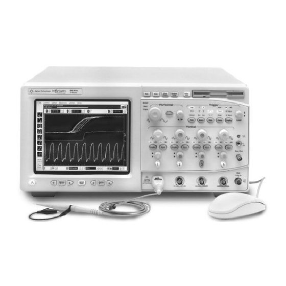
Setting Up the Oscilloscope To turn on the oscilloscope To turn on the oscilloscope 1 Depress the power switch in the lower left-hand corner of the oscilloscope front panel. Figure 1-23 Turning on the Oscilloscope After a short initialization period, the oscilloscope display appears. The oscilloscope is ready to use. -
Page 33: To Turn Off The Oscilloscope
Setting Up the Oscilloscope To turn off the oscilloscope To turn off the oscilloscope 1 Depress the power switch at the lower left-hand corner of the oscilloscope front panel. Even though the Infiniium oscilloscope is based on the Windows 98 operating system, shuting down the oscilloscope without going through the normal Windows 98 shutdown process is perfectly safe. -
Page 34: To Verify Basic Oscilloscope Operation
To verify basic oscilloscope operation 1 Connect an oscilloscope probe to channel 1. 2 Attach the probe to the calibration output on the front panel of the oscilloscope. Use a probe grabber tip so you do not need to hold the probe. The calibration output is marked with a square wave symbol. - Page 35 Setting Up the Oscilloscope To verify basic oscilloscope operation 5 Move the mouse pointer to the graphical interface enable button and click once using the left mouse button. The graphical interface enable button is in the upper-right corner of the display. 6 Move the mouse around the mouse pad and verify that the pointer follows on the screen.
-
Page 36: To Clean The Oscilloscope
Setting Up the Oscilloscope To clean the oscilloscope To clean the oscilloscope • Clean the oscilloscope with a soft cloth dampened with a mild soap and water solution. C A U T I O N Do not use too much liquid in cleaning the oscilloscope. Water can enter the Infiniium front panel, damaging sensitive electronic components. -
Page 37: Working In Comfort
Working in Comfort... - Page 38 Introduction To optimize your comfort and productivity, it is important that you set up your work area correctly and use your Infiniium oscilloscope properly. With that in mind, we have developed some set-up and use recommendations for you to follow based on established ergonomic principles.
-
Page 39: About Repetitive Strain Injury
Working in Comfort About Repetitive Strain Injury About Repetitive Strain Injury Because your comfort and safety are our primary concern, we strongly recommend that you use the Infiniium oscilloscope in accordance with established ergonomic principles and recommendations. Scientific literature suggests that there may be a relationship between injury to soft tissues— especially in the hands and arms—and prolonged improper use of keyboards or other equipment requiring repeated motions of the hands and forearms. -
Page 40: Mice And Other Input Devices
Working in Comfort Mice and Other Input Devices Mice and Other Input Devices Various aspects of using mice and other input devices may increase your risk of discomfort or injury. Observing the following recommendations may reduce that risk. • Try to keep your hand, wrist, and forearm in a neutral position while using your mouse or other input device. -
Page 41: Using The Oscilloscope
Using the Oscilloscope... - Page 42 Using the Oscilloscope The Infiniium Oscilloscope is designed to be easy to use. • The familiar front-panel oscilloscope interface with knobs and keys is optimized for the most common kinds of troubleshooting tasks and basic measurements. See “Using the Front Panel” on page 3-3. •...
- Page 43 Using the Front Panel The Infiniium Oscilloscope front panel has been designed to give you direct access to the functions needed to perform the most common measurements needed in troubleshooting, using a traditional oscilloscope interface. Knobs and keys are included to enable direct setting of vertical and horizontal parameters.
- Page 44 Using the Oscilloscope Front Panel Figure 3-1 shows the Infiniium Oscilloscope front panel. Figure 3-1 Horizontal Trigger Acquisition and controls controls general controls Marker and Measurement Controls Power Switch Vertical controls Infiniium Oscilloscope Front Panel Using the front panel, you can configure the Infiniium Oscilloscope for most troubleshooting tasks.
- Page 45 Using the Oscilloscope Acquisition and General Controls Using the acquisition and general controls, you control whether the oscilloscope is running or stopped. Other keys allow you to reset the oscilloscope to its factory default setup, automatically configure the oscilloscope for the current input signals (Autoscale), or erase the waveforms from the display.
- Page 46 Using the Oscilloscope Marker and Measurement Controls Using the marker and measurement controls, you control two sets of markers within the oscilloscope graticule. You use markers to make more accurate measurements of waveform events than you could make visually. Both time and voltage differences between the markers are updated continuously on the screen.
-
Page 47: To Set The Oscilloscope To A Known Starting Condition
Using the Oscilloscope To set the oscilloscope to a known starting condition To set the oscilloscope to a known starting condition • Press the Default Setup key. You can set up the oscilloscope for many different kinds of complex measurements. To easily reset the oscilloscope to a known measurement configuration, use the Default Setup key. -
Page 48: To Start And Stop Waveform Acquisition
Using the Oscilloscope To start and stop waveform acquisition To start and stop waveform acquisition • To start waveform acquisition, press the Run key. The oscilloscope begins acquiring data. When it receives a trigger signal, it finishes acquiring data, updates the display, then starts another acquisition cycle if it is in triggered or auto trigger mode. -
Page 49: To Clear The Waveform Display
Using the Oscilloscope To clear the waveform display To clear the waveform display • Press the Clear Display key. The oscilloscope clears the waveform display. If the oscilloscope is in Run mode and is receiving triggers, it will update the display as it collects new waveform data. -
Page 50: To Turn A Channel On Or Off
Using the Oscilloscope To turn a channel on or off To turn a channel on or off • To turn a channel on, press the channel number key until it is illuminated. To turn it off, press the channel number key again. If you are not using a particular channel, you can turn it off. -
Page 51: To Change Input Impedance And Input Coupling
Using the Oscilloscope To change input impedance and input coupling To change input impedance and input coupling • To change the input impedance, press the Input key until the LED for the desired impedance is illuminated. Choices are 50 Ω and 1 MΩ. •... -
Page 52: To Adjust Vertical Scale And Offset
Using the Oscilloscope To adjust vertical scale and offset To adjust vertical scale and offset • To make the waveform bigger, turn the vertical scale knob clockwise. To make it smaller, turn the knob counter-clockwise. The vertical scale knob is the larger of the two knobs for a channel. It is marked with a set of sine wave symbols. -
Page 53: To Adjust Sweep Speed And Horizontal Position
Using the Oscilloscope To adjust sweep speed and horizontal position To adjust sweep speed and horizontal position • To stretch the waveform horizontally, turn the sweep speed knob clockwise. To shrink it horizontally, turn the knob counter-clockwise. The sweep speed knob is the larger of the two horizontal control knobs. It is marked with a set of sine wave symbols. -
Page 54: To Magnify A Part Of The Waveform Using Delayed Sweep
Using the Oscilloscope To magnify a part of the waveform using delayed sweep To magnify a part of the waveform using delayed sweep • To turn on the delayed sweep, press Delayed. To turn it off, press Delayed again. The waveform display area splits into two regions. The top one is the main sweep. -
Page 55: To Set The Oscilloscope To Trigger On An Edge
Using the Oscilloscope To set the oscilloscope to trigger on an edge To set the oscilloscope to trigger on an edge 1 Press and release the Mode key until the Edge LED indicator is illuminated. 2 Press and release the Source key until the desired source LED is illuminated. -
Page 56: To Use The Markers
Using the Oscilloscope To use the markers To use the markers Markers make it easier to make precise measurements because the marker measurement readouts show exact voltage and time positions for the markers. The measurements are based on actual waveform data from the acquisition system, not on approximations based on the display position, so you can be sure that the values are highly accurate. -
Page 57: To Use The Quick Measurements
Using the Oscilloscope To use the quick measurements To use the quick measurements • To turn on the quick measurement display, press the QuickMeas key. The four preset measurements defined in the Quick Measurement configuration are enabled and results are displayed on the screen for the first waveform source. -
Page 58: To Reinitialize The Oscilloscope
Using the Oscilloscope To reinitialize the oscilloscope To reinitialize the oscilloscope When you need to restore the oscilloscope to a known configuration, use the Default Setup key. If you press the Default Setup key and the oscilloscope does not seem to be functioning properly, try cycling power. If the oscilloscope still does not seem to function properly, use the following key-down powerup procedure. - Page 59 Using the Graphical Interface With the graphical interface for the Infiniium Oscilloscope, you can access all the configuration and measurement features of the oscilloscope through an easy-to-use system of menus, tool bars, dialog boxes, icons, and buttons. Full-Screen Mode Full-screen mode maximizes the waveform viewing area and removes the graphical interface menus and toolbars so you can concentrate on your measurement.
- Page 60 Using the Oscilloscope Figure 3-14 Trigger level reference indicator Horizontal and trigger status bar Run/stop mode Horizontal Sweep (run shown in position speed green, stop in (delay) Trigger red) level Horizontal reference indicators (left, center, right) —horizontal delay is time at the highlighted arrow Infiniium Oscilloscope Bottom of Display in Full-Screen Mode...
- Page 61 Using the Oscilloscope Graphical Interface Mode Click the graphical interface enable button to switch to the graphical interface. When the graphical interface is enabled, the display looks like the following two figures. See “To switch between the graphical interface and full-screen mode” on page 3-30. Figure 3-15 This button enables Turn this...
- Page 62 Using the Oscilloscope Figure 3-16 See more measurements Turn off any measurements that are running Access (use Clear display horizontal sweep Stop to reset/restart trigger position speed Trigger measurements) level (delay) Setup Clear dialog display Access the Horizontal Setup Print dialog box screen Infiniium Oscilloscope Bottom of Display in Graphical Interface Mode...
- Page 63 Using the Oscilloscope You can still use the front panel when the graphical interface is enabled. All changes made to the front-panel settings are reflected in the graphical interface, and changes made using the graphical interface are reflected in the front panel where applicable. Use whichever interface is easiest for you in a particular measurement situation.
- Page 64 Using the Oscilloscope For each measurement currently Geometric Measurement Indicators running, a geometric indicator at the measurement location on the waveform corresponds to an identical indicator in the measurement results readout. This makes it easy for you to verify that the readout shows results for the correct waveform and the correct feature on that waveform.
- Page 65 Using the Oscilloscope Tab Display Area The tab display area located beneath the waveform viewing area appears when a measurement is on, mask testing is enable, a histogram is enabled, markers are on, or color graded persistence is on. Figure 3-17 Tab Display Area The display area shows information and statistics for the particular tab that is selected.
- Page 66 Using the Oscilloscope When the graphical interface is enabled, two Waveform Manipulation features are available that can simplify your work with waveforms: • Direct Manipulation—you can use the mouse to click and drag waveforms to new vertical positions, which changes the vertical offset, or to new horizontal positions, which changes the horizontal position or delay value.
- Page 67 Using the Oscilloscope To reinitialize the oscilloscope You can use the menu bar for most oscilloscope configuration functions. Context-sensitive menus, which pop up to provide a selection of commands within particular regions of the user inteface, are available in the following regions: •...
- Page 68 Using the Oscilloscope To reinitialize the oscilloscope The middle of the bar contains the Horizontal settings and controls horizontal settings and controls. Leftmost is a button, labeled with an “H.” Clicking on this will display the horizontal setup dialog box. Next is the current sweep speed.
- Page 69 Using the Oscilloscope To reinitialize the oscilloscope keypad that allows you to set a particular trigger level. You can also click on the up and down arrows to the right of the setting to increase or decrease the trigger level, respectively. Or, you can click on the trigger reference indicator at the right side of the display and drag it up or down to change the trigger level.
-
Page 70: To Switch Between The Graphical Interface And Full-Screen Mode
Using the Oscilloscope To switch between the graphical interface and full-screen mode To switch between the graphical interface and full- screen mode • To enable graphical interface mode, click on the outlined square wave button in the upper right-hand corner of the display. The button changes state, and the menus and measurement toolbar appear. -
Page 71: To Perform Basic User Interface Operations
Using the Oscilloscope To perform basic user interface operations To perform basic user interface operations • To move the mouse pointer on the screen, move the mouse on the mouse pad. If you run out of room on the mouse pad surface, pick up the mouse and set it down on the mouse pad where you will have room for motion. - Page 72 Using the Oscilloscope To perform basic user interface operations Figure 3-19 Click and drag the Click one of these title bar to move the Close buttons to dialog box on the close the dialog box screen Click to put a check mark in the check box and Click on the upward enable Connect Dots...
-
Page 73: To Select A Command From The Menu Bar
Using the Oscilloscope To select a command from the menu bar To select a command from the menu bar 1 Click on a menu bar item. 2 Move the pointer to the desired menu item. 3 Click the mouse button. The desired command is executed, or a dialog box is presented for you to configure the oscilloscope. -
Page 74: To Select A Command From A Context-Sensitive Menu
Using the Oscilloscope To select a command from a context-sensitive menu To select a command from a context-sensitive menu 1 Move the mouse pointer to a particular area of the display in which you want to change the oscilloscope configuration. Context-sensitive menus provide quick access to commands and configuration items that relate only to the context of the particular graphical interface item in which they are found. - Page 75 Using the Oscilloscope To select a command from a context-sensitive menu Figure 3-23 Right-click in this region Right-click in this region to see the Acquisition to see the Measurement Setup context-sensitive Setup context-sensitive menu menu Right-click in the waveform display area to see the waveform context- sensitive menu...
-
Page 76: To Change The Mouse Settings
Using the Oscilloscope To change the mouse settings To change the mouse settings 1 Select Utilities, then Preferences, then select Mouse. You will see the dialog in figure 3-24. • To swap the functions of the mouse buttons, click the Swap Buttons check box until a check mark appears. -
Page 77: To Start And Stop Waveform Acquisition
Using the Oscilloscope To start and stop waveform acquisition To start and stop waveform acquisition • To start waveform acquisition, click the start button at the bottom of the waveform display area. • To stop waveform acquisition, click the stop button at the bottom of the waveform display area. -
Page 78: To Clear The Waveform Display
Using the Oscilloscope To clear the waveform display To clear the waveform display • Click the clear display button at the bottom of the waveform display. See figure 3-26. You can still use the Clear Display key on the front panel while the graphical interface is enabled. -
Page 79: To Print The Screen
Using the Oscilloscope To print the screen To print the screen • Click the print button at the bottom of the waveform display. See figure 3-27. Infiniium prints the screen to the default printer according to the configuration that you have selected in the Printer Setup dialog box. Figure 3-27 Click this button to print the screen... -
Page 80: To Turn A Channel On Or Off
Using the Oscilloscope To turn a channel on or off To turn a channel on or off • To turn a channel on, click the check box next to the channel number so that a check mark appears in the box. To turn a channel off, click the check box again to clear it. -
Page 81: To Adjust The Vertical Offset
Using the Oscilloscope To adjust the vertical offset To adjust the vertical offset • Click and hold the left mouse button on the waveform you want to move, then drag the mouse up or down to move the waveform to the desired offset. - Page 82 Using the Oscilloscope To adjust the vertical offset Figure 3-29 Click to access the Channel Setup dialog, then set vertical offset using the spin box or numeric keypad..or click on the ground reference indicator and drag it up or down to change ...or click on the waveform and...
-
Page 83: To Adjust Vertical Scaling
Using the Oscilloscope To adjust vertical scaling To adjust vertical scaling • To make the waveform bigger, click on the larger waveform button next to the channel number near the top of the display. To make the waveform smaller, click on the smaller waveform button. See figure 3-30. -
Page 84: To Access The Channel Setup
Probes button. You can set attenuation ratio, attenuation units, and measurement units for the probe, or perform a probe calibration. For Agilent Technologies probes that are compatible with the AutoProbe Interface, the oscilloscope will automatically set these characteristics (except for skew) after identifying the probe when it is connected to the channel input. -
Page 85: To Set The Horizontal Reference Point
Using the Oscilloscope To set the horizontal reference point To set the horizontal reference point • Click on one of the arrows at the bottom of the waveform display. The selected horizontal reference is highlighted. The vertical arrows at the bottom of the display correspond to the left, center, and right horizontal reference points. -
Page 86: To Adjust Sweep Speed
Using the Oscilloscope To adjust sweep speed To adjust sweep speed • To stretch the waveform horizontally, click the larger waveform button next to the horizontal sweep speed setting at the bottom of the waveform display. To shrink the waveform horizontally, click the smaller waveform button. -
Page 87: To Adjust Horizontal Position
Using the Oscilloscope To adjust horizontal position To adjust horizontal position The horizontal position is the time relative to the trigger at the highlighted horizontal reference point. • To zero the horizontal position, click the 0 button next to the position value at the bottom of the waveform display. -
Page 88: To Access The Horizontal Setup
Using the Oscilloscope To access the horizontal setup To access the horizontal setup • Click the horizontal setup button at the bottom of the waveform display. • Select Horizontal from the Setup menu. See figure 3-35. Using the Horizontal Setup menu, you can set sweep speed, position, and the horizontal reference. -
Page 89: To Zoom On A Section Of The Waveform
Using the Oscilloscope To zoom on a section of the waveform To zoom on a section of the waveform 1 Click and hold the left mouse button in a blank space within the waveform display area, then drag the mouse to draw a rectangle around the areas of interest on the waveform(s). - Page 90 Using the Oscilloscope To zoom on a section of the waveform Figure 3-36 Click and hold the mouse button, drag to create a selection rectangle, then click inside the rectangle to zoom the display on the waveforms inside the rectangle Zooming on a Section of the Waveform 3-50...
-
Page 91: To Move The Markers Using The Graphical Interface
Using the Oscilloscope To move the markers using the graphical interface To move the markers using the graphical interface 1 Turn on the markers. You can use the Marker A and Marker B keys on the front panel, or select Markers from the Measure menu. -
Page 92: To Make A Measurement On A Waveform
Using the Oscilloscope To make a measurement on a waveform To make a measurement on a waveform • Click and hold the mouse button on a measurement icon, then drag the icon to the waveform event you want to measure. Release the mouse button. - Page 93 Using the Oscilloscope To make a measurement on a waveform Figure 3-38 Channel numbers associate the measurement results with the channel waveform In some cases, geometric icons are also displayed to associate the Waveform Measurements 3-53...
-
Page 94: To Access The Trigger Setup
Using the Oscilloscope To access the trigger setup To access the trigger setup • Click the trigger setup button at the bottom of the waveform display. • Select Trigger from the Setup menu. The trigger setup dialog allows you to select any of the different modes of triggering supported by the oscilloscope—Edge, Glitch, or Advanced, with choices under Advanced of Pattern, State, Delay by Time, Delay by Events, Violation, or Video. -
Page 95: To Set An Edge Trigger
Using the Oscilloscope To set an edge trigger To set an edge trigger 1 Click on the trigger setup button at the bottom of the waveform display. This brings up the trigger configuration dialog. See “To access the trigger setup.” 2 Click on Edge. -
Page 96: To Enable 8.0 Gsa/S Sampling Mode On The 54845A
Using the Oscilloscope To enable 8.0 GSa/s sampling mode on the 54845A To enable 8.0 GSa/s sampling mode on the 54845A 1 Select Acquisition from the Setup menu. 2 Click the radio button labeled “8 GSa/s, 64k pts (Channels 1, 3)” under Configuration in the Acquisition Setup dialog box. -
Page 97: To Enable 4.0 Gsa/S Sampling Mode On The 54835A
Using the Oscilloscope To enable 4.0 GSa/s sampling mode on the 54835A To enable 4.0 GSa/s sampling mode on the 54835A 1 Select Acquisition from the Setup menu. 2 Click the radio button labeled “4 GSa/s, 64k pts (Channels 1, 3)” under Configuration in the Acquisition Setup dialog box. -
Page 98: To Set Dialog Box Preferences
Using the Oscilloscope To set dialog box preferences To set dialog box preferences • To change the background for the dialog boxes used by the oscilloscope, select Utilities, then User Preferences. Then select Opaque, Translucent, or Transparent in the User Preferences dialog box. - Page 99 Using the Oscilloscope To set dialog box preferences Figure 3-43 Select one of these commands to change how dialog boxes look on the screen Select this command to allow many dialog boxes to be present on the screen at one time Setting Dialog Box Options 3-59...
- Page 100 Using the Oscilloscope To set dialog box preferences Figure 3-44 Multiple Active Dialogs (Opaque) 3-60...
-
Page 101: To Install The Printer Software
Using the Oscilloscope To install the printer software To install the printer software When adding a printer or modifying the printer setup, you can either: • Configure the scope to use the printer attached to your network. Before doing this, you must configure the network (see “To set up the network”... - Page 102 Using the Oscilloscope To install the printer software If you choose to add a Plug and Play printer, the installation process automatically sets up the printer after you reboot the oscilloscope. 4 Read the directions in the Adding a Printer window carefully. Because you will be cycling power on the oscilloscope, you may want to record the instructions in the Adding a Printer window before you continue.
- Page 103 Using the Oscilloscope To install the printer software When the Add Printer Wizard starts, it displays the following dialog box: Add Printer Wizard Startup 7 Click Next. The following printer selection dialog appears: Figure 3-46 Choose to Set Up Local or Network Printer 8 If you are going to use a network printer, click Network printer.
- Page 104 Using the Oscilloscope To install the printer software 9 If you selected Network printer, you’ll need to know the names of the network server and the network printer to type in the next dialog box. If you do not know these names, ask your System Administrator now. 10 Click Next to access the network printer name dialog box.
- Page 105 Using the Oscilloscope To install the printer software 13 Select the printer manufacturer from the left-hand list. Then select the printer model from the right-hand list. Then skip the next step. If Your Printer Is Not Listed If your printer model or manufacturer is not listed, you must have the printer driver disk with drivers for Microsoft Windows 98 to load the appropriate driver.
- Page 106 17 If you are using a serial printer, set the baud rate, data bits, parity, stop bits, and handshake to match the settings for your printer. If you are using a parallel printer, ensure that the checkbox for “Spool MS-DOS print jobs” is cleared, and that “Check port state before printing”...
- Page 107 Using the Oscilloscope To install the printer software Figure 3-50 Printer Name Dialog 19 Type a name for the printer, or accept the default name that is displayed. 20 Click Yes to use this printer as the default printer. Then click Next. The Printer Test Page dialog appears.
- Page 108 Using the Oscilloscope To install the printer software 21 Optional — Make sure that your printer is powered on. 22 Click Yes to print a test page. Then click Finish. The oscilloscope sends the printer test page and displays the Test Page Complete dialog.
-
Page 109: To Set Up The Network
The following screen is displayed. Figure 3-53 Network Properties Screen Unless you are the System Administrator for your company’s network, Agilent Technologies recommends that you have System Administrator configure the network for you. When you are done, click OK. 3-69... -
Page 110: To Recover Your Infiniium Hard Disk
Using the Oscilloscope To recover your Infiniium hard disk To recover your Infiniium hard disk Your Infiniium oscilloscope comes with a set of recovery disks called the User’s Hard Drive Recovery Disks. You should use these recovery disks to restore your hard drive in the rare event that something may have destroyed the Windows operating system or the Infiniium application software. -
Page 111: Using The Built-In Information System
Using the Built-In Information System... - Page 112 Using the Built-In Information System Most of the documentation for using the Infiniium Oscilloscope is included in its built-in information system. The built-in information system contains the information generally found in a User’s Guide. The information system is available only when the graphical interface is enabled, and is accessible from the menu bar and from dialog boxes.
- Page 113 Using the Built-In Information System • VoiceControl discusses the operation and use of VoiceControl which is an option that you can order with you Infiniium oscilloscope. • Locating a Control is a visual guide to the location of every oscilloscope control in the graphical user interface. •...
-
Page 114: To Access The Information System
Using the Built-In Information System To access the information system To access the information system • Select Contents from the Help menu. The Contents page for the oscilloscope information system is displayed. To Use the Information System You must select the graphical interface before you can access the information system. - Page 115 Using the Built-In Information System To access the information system Access Methods The information system provides three methods for finding the information you need. The Contents topic is shown when you access the information system from the Help menu. It looks like the following figure.
- Page 116 Using the Built-In Information System To access the information system Viewing the Information System Window The Information System window will always stay on top of the interface display, so you can refer to it while working with the oscilloscope. You can move the window around the screen or resize it to make it easier to use.
- Page 117 Using the Built-In Information System To access the information system Hyperlinks throughout the information system allow you to reach the information you need. Most hyperlinks will be in blue underlined text, but some hyperlinks also have buttons (many of the reference topics) or tabs (in setup guide topics).
- Page 118 Using the Built-In Information System To access the information system Figure 4-4 Moves to Prints this the Index topic on the local printer Moves to Contents topic Displays the list of related topics Shows you how to find the user interface control discussed in the topic Click on any...
- Page 119 Using the Built-In Information System To access the information system Figure 4-5 Click a tab to move to the Overview, or to the details for a specific step..or click on the button next to a label for a step to move to the details for that step Setup Guide Topic...
-
Page 120: To Select The Built-In Information System Language
Using the Built-In Information System To select the built-in information system language To select the built-in information system language 1 Select the Select Help Language command from the Help menu. 2 Choose the help language from the drop-down list box options. 3 Click the Close button. -
Page 121: To Navigate Through The Information System
Using the Built-In Information System To navigate through the information system To navigate through the information system Once you are in the help system windows, you may need to navigate through them to find the information you need. For most topics: •... -
Page 122: To Access Context-Sensitive Information
Using the Built-In Information System To access context-sensitive information To access context-sensitive information • To see overview information for items in a dialog box, click the Help button in that dialog box. • To get information on a particular user interface element, click on the question mark button at the upper right-hand corner of a dialog box, then point to the element. - Page 123 Index Numerics check box 3-31, 3-32 checking the oscilloscope 1-3 4.0 GSa/s sampling 3-57 back panel connections 1-11, 1-17, 1-22, choosing 54835 1-23, 1-25 commands 3-33, 3-34 4.0 GSa/s sampling on 3-57 backlight 1-28 list items 3-31 54845 behavior of information system windows cleaning the oscilloscope 1-32 8.0 GSa/s sampling on 3-56 clear display 3-5...
- Page 124 Index probes 1-21 information system 4-2 connecting 1-25 constraints on waveform movement display area graphical interface 3-2, 3-19 3-41 waveforms 3-20, 3-25 arrangement of 3-23 contents display format 4-2 button 3-30 information system 4-4 display layout controls 4-3 of oscilloscope package 1-3 customizing 3-24, 3-52 mode 3-21, 3-22, 3-30 contents topic 4-5...
- Page 125 Index Arrow 3-16 quick measurements 3-17 Channel 3-10 waveform bigger or smaller 3-12, icons Clear Display 3-9 3-43 dragging to waveform 3-23 Coupling 3-15 manipulating waveforms 3-26, 3-41 learning functions of 3-24 Default Setup 3-7 manuals 1-3, 1-4, 1-5, 1-6 measurement 3-21, 3-22, 3-23, 3-52, Delayed 3-14 Marker A key 3-16...
- Page 126 Index switching between graphical oscilloscope configuration 1-23 interface and full-screen 3-30 cleaning 1-32 network 3-61 trigger 3-54 inspecting 1-3 plug and play 3-61 mouse resetting 3-7 ports 3-65, 3-66 click 3-31 using 3-2 printer software connecting 1-11 oscilloscope controls 4-3 installing 3-61 moving 3-31 oscilloscope feet 1-26...
- Page 127 Index Using the Mouse 2-4 default 1-30, 3-5, 3-7 switching between graphical interface run 3-37 dialog boxes 3-58 and full-screen modes 3-30 button 3-21, 3-22 horizontal 3-28, 3-48 Run key 3-8 ports 3-65, 3-66 run/stop trigger 3-28, 3-54, 3-55 Tab display area 3-25 controls 3-27 Setup Guide 4-3 tabs...
- Page 128 Index location 3-28 parameters, where set up 3-5 waveform position 3-45 magnifying 3-5, 3-14 setting edge 3-15 stretching and shrinking 3-13 setup 3-28, 3-54, 3-55 waveform display area 3-20, 3-25 setup button 3-21, 3-22, 3-54, 3-55 waveform features slope 3-15, 3-55 measurements on 3-52 source 3-15, 3-55 moving markers to 3-51...
- Page 129 This product was tested in a typical configuration with Agilent Technologies test systems. Colorado Springs, 02/12/1999 Ken Wyatt, Quality Manager European Contact: Your local Agilent Technologies Sales and Service Office or Agilent Technologies GmbH, Department ZQ / Standards Europe, Herrenberger Strasse 130, D-71034 Böblingen Germany (FAX: +49-7031-14-3143)
- Page 130 Product Regulations Safety IEC 1010-1: 1990+A1 / EN 61010-1: 1993 UL 3111 CSA-C22.2 No. 1010.1:1993 This product meeets the requirements of the European Communities (EC) EMC Directive 89/336/EEC. Emissions EN55011/CISPR 11 (ISM, Group 1, Class A equipment), IEC 555-2 and IEC 555-3 Immunity EN50082-1 Code...
- Page 131 (see the following warnings). Hazardous voltage symbol. reduction), make sure the In addition, note the external Agilent Technologies makes common terminal is markings on the instrument no warranty of any kind with connected to the earth that are described under regard to this material, terminal of the power source.
- Page 132 54810-97029, May 1999 a service facility designated or consequential damages, by Agilent Technologies. For 54810-97041, Sept. 1999 whether based on contract, products returned to Agilent tort, or any other legal 54810-97045, Jan. 2000 Technologies for warranty theory.