Sharp XE-A212 Service Manual
Hide thumbs
Also See for XE-A212:
- Instruction manual (404 pages) ,
- Faq (21 pages) ,
- Quick start manual (6 pages)
Table of Contents
Advertisement
Quick Links
q
CHAPTER 1. SPECIFICATIONS . . . . . . . . . . . . . . . . . . . . . . . . . . . . 1
CHAPTER 2. OPTIONS . . . . . . . . . . . . . . . . . . . . . . . . . . . . . . . . . . . 5
CHAPTER 3. MASTER RESET AND PROGRAM RESET. . . . . . . . . 5
CHAPTER 4. HARDWARE DESCRIPTION . . . . . . . . . . . . . . . . . . . . 6
CHAPTER 5. DIAGNOSTIC PROGRAM . . . . . . . . . . . . . . . . . . . . . 12
CHAPTER 6. IPL FROM EP-ROM . . . . . . . . . . . . . . . . . . . . . . . . . . 16
CHAPTER 8. CIRCUIT DIAGRAM AND PWB LAYOUT . . . . . . . . . 17
Parts marked with "!" are important for maintaining the safety of the set. Be sure to replace these parts with specified
ones for maintaining the safety and performance of the set.
SERVICE MANUAL
CONTENTS
CONNECTING THE RS-232 CABLE . . . . . . . . . . . . . 16
SHARP CORPORATION
CODE : 00Z
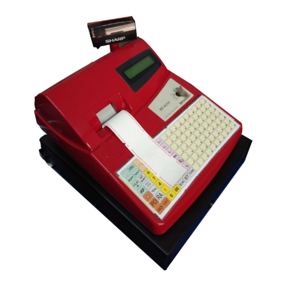
ELECTRONIC
CASH REGISTER
XE-A212
MODEL
(V version)
This document has been published to be used
for after sales service only.
The contents are subject to change without notice.
XEA212VSME
Advertisement
Table of Contents

Related Manuals for Sharp XE-A212


Summary of Contents for Sharp XE-A212
-
Page 1: Table Of Contents
CODE : 00Z XEA212VSME ELECTRONIC CASH REGISTER XE-A212 MODEL (V version) CONTENTS CHAPTER 1. SPECIFICATIONS ......1 CHAPTER 2. -
Page 2: Chapter 1. Specifications
Department keys Inner cover Multiplication key Decimal point key Clear key 2. RATING 00, 0~9 Numeric keys XE-A212 No sale key Weight 11.3kg GC RCPT Guest check receipt key Dimensions 421 (W) x 429 (D) x 305 (H) mm AUTO... - Page 3 The mode switch has these settings: • Clerk code or Mode name This mode locks all register operations. (AC power turns off.) The mode you are in is displayed. When a clerk is assigned, the No change occurs to register data. clerk code is displayed in the REG or OP X/Z mode.
- Page 4 6. PRINTER 7. DRAWER 1) Printer [OUTLINE] • Part number : M-T53II • Standard equipment: Yes (1) • NO. of station : 1 (Receipt or journal) • Max. number of additional drawers: 0 • Validation : No. • The drawer consists of: •...
- Page 5 8. BATTERY 1) MEMORY BACK UP BATTERY For memory back up, the dry battery AA (3 pieces) are needed. 1. Memory holding time: Approx. 1 year after New dry batteries are installed. 2. Battery exchange method: When the low battery symbol “L” lights up, replace the batteries (3 AA) by the following method;...
-
Page 6: Chapter 2. Options
CHAPTER 2. OPTIONS 1. OPTIONS (No) 2. SERVICE OPTIONS (No) 3. SUPPLIES PRICE NAME PARTS CODE DESCRIPTION RANK TPAPR6645RC05 Roll paper 5roll/pack 4. SPECIAL SERVICE TOOLS PRICE NAME PARTS CODE DESCRIPTION RANK UKOG-6705RCZZ RS-232 Loop-back connector CHAPTER 3. MASTER RESET AND PROGRAM RESET 1. -
Page 7: Chapter 4. Hardware Description
512KB address 40000h ~ 7FFFFh 256KB FLASH ROM 512KB Reserve /CS0 area BANK 4, 5: address 40000h ~ 7FFFFh 256KB x 2 SHARP LH28F004BVT FLASH /CS0 area BANK 0 address 80000h ~ FFFFFh 256KB PRINTER (Moves to Bank 1 when... - Page 8 3. PRINTER CONTROL 3-1. STEPPING MOTOR CONTROL Conduction pulse width: Refer to the M-T53II specifications. The two phase Bi-Polar stepping motor is driven at a constant voltage OFF time of print strobe : Conduction strobe OFF time between dots by SANYO LB1838M. min.
- Page 9 4. CPU • M16C/64A Group: M30620SAFP M16C/64A PORT MEMORY SPACE: NORMAL MODE PROCESSOR MODE: MICRO PROCESSOR MODE • Processor mode = Microprocessor mode It is used by (SEPARATE BUS 8bit Width) • Internal reserve area, without expansion • Multi function 16-bit Timer: Output system 5 lines + input system 6 lines •...
- Page 10 <Power supply/CONTROL pins> PORT Pin name Function PORT Pin name Function BYTE BYTE Connected to VDD Connected to VDD CNVss CNVss Connected to VDD connected to GND /RESET /RESET AVss AVss Connected to GND Xout Xout OPEN Vref Vref Connected to VDD Connected to GND AVcc AVcc...
- Page 11 5-3. KEYSCAN MATRIX PENDING Others MODE Time X1/Z1 X2/Z2 KEYBD Others HEAD DRAWER RS-232 OPEN KEYBD : 1=Normal Keyboard/0=Flat Keyboard HEAD UP : 1=Up/0=Down : 1=Paper End/0=Paper Not End DRAWER OPEN : Reserved (1=Open/0=Close) RS-232 CI1 : 5-4. DISPLAY 6. POWER SUPPLY The machine has an LCD display, 5 x 7 dots, 2 lines, 16digits, at the After detection of /POFF, power interruption must be executed within 10ms.
- Page 12 9. A/D CONVERSION 11. RESET The machine has the following four signals at the A/D conversion ports. The RESET signal is canceled when the power source of the device which used the 5V system (VCC, VDD, VLED) reaches the operating <CPU’s PORT>...
-
Page 13: Chapter 5. Diagnostic Program
CHAPTER 5. DIAGNOSTIC PROGRAM 1. TEST ITEMS 2. DESCRIPTION OF EACH DIAG PROGRAM The test items are as follows: 1) DISPLAY BUZZER TEST 1 Key operation Code Description 100 3 Display buzzer test Key code 2 Test procedure Printer test OP display D I S P B U Z Z E R... - Page 14 3) PRINTER TEST 5) MODE SWITCH TEST 1 Key operation 1 Key operation 105 3 102 3 2 Test procedure 2 Test procedure OP display M O D E P G M OP display P G M P R I N T E R 1 0 5 MODE: PGM_ _OP X/Z_REG_MGR_X1/Z1_X2/Z2__...
- Page 15 8) DRAWER 1 OPEN & SENSOR TEST 10) CPU INTERNAL RAM TEST 1 Key operation 1 Key operation 110 3 121 3 2 Test procedure 2 Test procedure OP display The test program tests internal RAM (10 Kbytes) of the CPU. P G M D R A W E R The contents of memory must be stored before and after this test.
- Page 16 11) FLASH ROM TEST 13) RS232C TEST 1 Key operation Install the RS232C loopback connector. 130 3 1 Key operation 2 Test procedure 500 3 2 Test procedure The test program checks that the checksum of the flash ROM (Bank0: F80000H ~ FFFFFH). The test program checks the control signals.
-
Page 17: Chapter 6. Ipl From Ep-Rom
Before working on the installation, unplug the AC cord from the AC out- THE RS-232 CABLE let. 1. Open the top cabinet. When connecting the RS-232 cable to the XE-A212, be sure to observe 2. Set the IPL switch (S1) to VCC position. the following condiiton: IPL switch Secure the attached core (RCORF6699BHZZ) to the RS-232 cable in the area within 20mm from the connector. -
Page 18: Chapter 8. Circuit Diagram And Pwb Layout
XE-A212V CIRCUIT DIAGRAM AND PWB LAYOUT – 17 –... - Page 19 XE-A212V CIRCUIT DIAGRAM AND PWB LAYOUT – 18 –...
- Page 20 XE-A212V CIRCUIT DIAGRAM AND PWB LAYOUT – 19 –...
- Page 21 XE-A212V CIRCUIT DIAGRAM AND PWB LAYOUT – 20 –...
- Page 22 XE-A212V CIRCUIT DIAGRAM AND PWB LAYOUT – 21 –...
- Page 23 XE-A212V CIRCUIT DIAGRAM AND PWB LAYOUT – 22 –...
- Page 24 XE-A212V CIRCUIT DIAGRAM AND PWB LAYOUT – 23 –...
- Page 25 XE-A212V CIRCUIT DIAGRAM AND PWB LAYOUT – 24 –...
- Page 26 MEMO...
- Page 28 COPYRIGHT 2003 BY SHARP CORPORATION All rights reserved. Printed in Japan. No part of this publication may be reproduced, stored in a retrieval system, or transmitted. In any form or by any means, electronic, mechanical, photocopying, recording, or otherwise, without prior written permission of the publisher.