Table of Contents
Advertisement
Advertisement
Table of Contents

Related Manuals for Yaesu FT-208R


Summary of Contents for Yaesu FT-208R
-
Page 2: Table Of Contents
CONTENTS PREFACE SECTION 1 GENERAL GENERAL DESCRIPTION ........1-1 SPECIFICATIONS . - Page 4 PREFACE The purpose of this manual is to provide the reader with information critical to the maintenance and repair of the FT-208R transceiver, as well as information useful for understanding its functions and operation more thoroughly. Technical explanations are geared toward providing a clear understanding of the overall system design, rather than attempting to cover many specific circuit details.
- Page 6 S E CT I ON 1-G EN E RAL GENERAL DESCRIPTION ..........1-1 SPECIFICATIONS ............
-
Page 8: General Description
FT-208R is the limited band scanning mode, whereby a favorite segment of the band may be scanned, instead of the entire band. The FT-208R may also be programmed via the keyboard to exclude a given section of the band, if desired. -
Page 9: Specifications
5 / 1 0 ±600 1 4 7 . 995 ( 1 800) 1 44.000- (see 145 .000 1 0/20 145 .990 NOTE) FT-208R MODEL CHART NOTE: Model Fis for use in Japan only, and cannot be readily converted to other Models. - Page 10 GENERAL S EM I C ON DU CTO R C O M PLE M EN T I Cs: Transistors: Diodes: HD44820A07 2SA9 50Y 1 S l 5 5 5 (Si) MC3 3 5 7 2SA1 l 7 5 E 1 SS53 (Si) MC 1 4069UB 2SC20 5 3...
-
Page 11: Top Panel Controls And Switches/Front Panel Switches
GENERAL TOP PANEL CONTROLS AND SWITCHES HIGH/LOW TX SHIFT SWITCH This is the main volume and power ON/OFF This is a miniature phone jack used to accom switch for the transceiver. modate an external earphone. SQL/TONE HIGH/LOW The squelch control silences the receiver audio This switch selects transmitter powers of 2.5 watts until a signal is received. -
Page 12: Bottom Panel Connections
This terminal is for use with the NC-7 and NC-8 chargers (optional). CAUTION Never attempt to insert the charge plug from the NC-9B/C or other metal material into the DC adapter jack on the bottom of the as the internal protection fuse will blow. FT-208R,... -
Page 13: Installation
GENERAL I N STALLATI O N ANTENNA CONSIDERATIONS The FT-208R comes equipped with a helical For base station use, gain antennas such as the rubber flexible antenna, which should be sufficient yagi, quad, stacked vertical, etc., will enhance long distance communications. These antennas are also for local work through repeaters, etc. -
Page 15: Battery Charger Information
FT-208R when operating your transceiver from mately 4 hours, the STANDARD mode in 1 5 a car. The PA-3 allows you to operate the FT-208R hours, and the T RICKLE mode may be used to while conserving battery charge, and the trickle... - Page 16 GENERAL FBA-2 NC-8 NC-8/FBA-2/FNB-2 NC-8/FT-208R NC-9C (for 220-234V AC) NC-9B (for 117V AC) 1 - 8...
- Page 17 GENERAL 0 1 0 1 SIVBIO RIOI 0102 CHARGE CONTA CT Pl Rl02 FIO I 2.7K I I I 234 v 200V l l OV 220V 117 v POWER TRANSFORMER PRIMARY CONNECTIONS NC-7 r----------- � ------, r-----------------------, 001 2SD23�Y ,.,, 2SC94�...
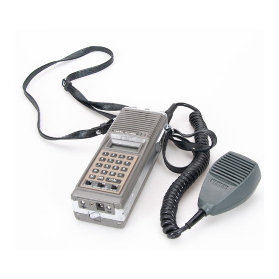
- Page 18 The microphone should have an impedance of 2000 ohms. See your Yaesu dealer for details of the YM-24A Remote Speaker Microphone. Once installed, the YM-24A can be held close to your ear during reception , allowing you to raise your FT-208R high above any obstructions.
-
Page 20: Operation
Now store another frequency in memory transmit. Release the PTT switch for receiver channel For example, to store 145 .125 recovery. If your FT-208R (Model B, C , D, E) MHz press "DIAL", and then is equipped with a tone burst switch, press "5125",... - Page 21 Repeater shifts of +600 kHz and -600 kHz After a 5 second stop on the channel for are built into the FT-208R. To select the shift moni taring, the scanner will again start to frequency, set the SHIFT switch to either the search other channels .
- Page 22 5 years. After this jump back to 1 44.750 MHz, continuing the period, please ask your Yaesu Dealer for a scan up to 1 4 5 . 7 5 0 MHz again. replacement. If the DOWN key is pressed instead, the The t o p panel HIGH-LOW switch m a y b e set display will scan from 1 44.750 MHz to the...
- Page 23 Tone Squelch Operation ( Option) Memory Backup Information 1 . When the optional FTS-3 2 tone squelch unit The FT-208R. memory channels are protected by a is installed, it may be activated by placing the memory backup lithium cell in the transceiver.
- Page 24 S E CTION 2 -TEC H N I CAL NOTES BLOCK DIAGRAM CIRCUIT DESCRIPTION ..........2-2 CRYSTAL DATA/PLL CIRCUIT FREQUENCY RELATIONSHIPS...
-
Page 26: Block Diagram
3. 58MHz HD44820A0"1 125 .595 MHz A,D, E MODE L MODEL 124. 5875MHz (""') ---· C ONT BO A R D C LOC K L<22 !! ��-� N _!_T__�=-���------------_J r=:=> D A TA BUS > FT-208R t""' BLOCK DIAGRAM "'"3... -
Page 27: Circuit Description
Q 11 4 is then biased for normal operation, thus standing of the FT-208R transceiver. Please refer allowing receiver recovery. VR102 sets the squelch to the schematic diagram for details. - Page 28 TECHNICAL NOTES The IF signal is fed to a balanced mixer, Q214 /Q21s where the 1 6 .9 MHz FM signal is (2SK193K), mixed with a local signal from the VCO , with the output being at the ultimate transmitting fre quency.
- Page 29 TECHNICAL NOTES CRYSTAL DATA Drive Equivalent Type of Frequency Capacitance Yaesu Remar ks Function Mode Resistance Level (.11 ) Holder (MHz) (pF) Part Number (Model) (mW) HC-1 8/T 1 6 .445 H0 1 02406 (B, C) X l O l Load C: 27pF <...
-
Page 30: Signal Level Diagrams
S ECTION 3- S E RVI C I N G OUTER COVER REMOVAL EXPLODED VIEWS SIGNAL LEVEL DIAGRAMS MAIN UNIT PARTS LAYOUT PLL UNIT PARTS LAYOUT PLL UNIT VOLTAGE CHART LEVEL DIAGRAM-PLL SECTION 3-10 CONTROL UNIT PARTS LAYOUTS 3-11 WIRING DIAGRAMS 3-15 MODIFICATIONS (FREQUENCY RANGE AND LOW POWER) 3-18... - Page 33 Contact Clip R0066790C Note 4 NOTE I Use only one spring. NOTE 2 Do not use for FT-208R. NOTE 3 FT-20 8R; Ser. No. 0 1 00 0 1 to 029999. NOTE 4 FT-208R; Ser. No. up to 03000 1 .
- Page 34 NOTE 4 FT-20 8 R ; Model A, F are PTT only. Other model is burst switch. NOTE 5 FT-208R. Do not used Model A, F . Other model is PTT switch. NOTE 6 Mount lamp switch applying adhesive inside frame.
- Page 35 SERVICING E X P L O D E D V I EW ( REPLACEABLE MECHANICAL PARTS Y AESU Part No. Item No. Nomenclature R306 6 7 1 0 Front Panel Keyboard Unit N5090006 R7069720 Note 1 Light Shield Chassis Bracket A R006 9 7 1 0 Chassis Bracket B R0069 7 1 1...
- Page 36 FT-208R LEVEL DIAGRAM (RECEIVER SECTION) 16.9MHz- 455k Hz TIO! ANT SW TIOI C I N J Ql04 Q I 0 4 Ql05 Ql06 QI06 QIOB QIOB QI0 9 0109 VRIOI Q l l 3 0105 0 1 1 4 0 1 1 4...
- Page 37 SERVICING FT-208R LEVEL DIAGRAM (TRANSMITTER SECTION) 0 1 01 VR202 02 17 0217 VR202 0 214 0 2 1 6 0 1 0 1 02 13 BASE COLLECTOR P I N 2 P I N 5 BASE PIN I HOT END CENTER...
-
Page 38: Main Unit Parts Layout
SERVICING MAI N U N I T PARTS LAYO UT MAIN UNIT VOLTAGE CHART ( DC VOLTS) MODE R 1 47 Q l O l 1 0.6 Q102 1 . 2 1 0.6 Q l 0 3 1 0.8/3.3 TX H/L Q 1 04 5 . -
Page 40: Pll Unit Voltage Chart
SERVICING P L L U N I T VOTAG E C HART PLL UNIT VOLTAGE CHART (DC VOLTS ) A.D.E.F A.D.E.F. A.D.E.F MODE 5.76MHz 90kHz 5 . 76MHz 5 (VDD) Q201 5 . 3 RX/TX 7.2MHz 7.2MHz 1 1 2.5kHz Q202 RX/TX A. -
Page 41: Level Diagram-Pll Section
SERVICING L EVEL D I AG R A M P L L S EC T I O N LOCAL IN 0203 EMITTER T204 T202 0205 Q205 0210 T204 BASE 0202 0203 0210 0202 0203 0205 COLLECTOR BASE LINK COLLECTOR BASE COLLECTOR BASE COLLECTOR... -
Page 42: Control Unit Parts Layouts
SERVICING C O N T ROL U N I T PARTS LAYO U T P rod . Lot( Seri ol N o . 0 1 000 1 - 0 6 9 9 9 9 ) When replacing the Backup Lithium Battery never allow your skm to touch the battery, as the battery will pick up oil from the skin and thus have its lifetime shortened due to current leakage through the oil. - Page 43 SERVICING C O N T R O L U N I T P A RTS LAYO U T P rod . Lot( Seri ol N o . 0 7000 1 & U P ) PB-2337 COMPONENT SIDE Viewed from component side Prod.Loi s.,.Nos o1xxxx1...
- Page 44 SERVICING Q3 0 1 CPU HD44820-A07 FUNCTION/WAVE FORM PORT TX "L" TX "H" PTT Press "L" DOWN Not used (Normally "H") Not used (Normally "H'') D l O SCANSTOP I BUSY STOP STOP "L" D l l SCANSTOP I CLEAR STOP STOP "H" D 1 2 KEY-E KEY (E) ROW OUT (Normally "L") KEY ON...
- Page 45 SERVICING POWER ON RESET PULSE CIRCUIT 1 3 �l-"12=--- - 0 3 01 PI N 21 I O mS � Q303 � r - H LT PULSE GENERATOR g � Q 303 FRAME CLOCK OSCILLATOR C IRCU IT Q303 � _Jr- HLT S IGNAL DELAY T I ME 6mS...
- Page 46 > i:z:: � r'-2 S H I FT M I C BURST B,C,D,E � � <t S 03 � <t GRAY to J02,P IN3 � to J02,P I N I CTONE SQ IN) � A,B,C,D,E Type SPO I COMPONENT S I DE...
- Page 47 SHIFT M IC � � LAMP � BURST C B,c,o,E <C (.!> <C (,:, CE)(T PTT> to J02 , PIN3 BL U � CTO'<E SO IN) A ,B,C,D,E T ype SPOI COMPONENT SIDE S UP Serial Nos . 07000 1 {.!) �...
- Page 48 � � r:i::: � H I / LOW (A,B,C ,D,E Type ) � <( SHIELD <( YEL( F Type) ..T, I �...
- Page 49 SERVICING MO D I F I CAT I ON S FREQUENCY RANGE MODIFICATIONS MODIFICATION OF THE FT-208R FOR 1 WATT OUTPUT IN THE LOW POWER This modification will enable your transceiver to POSITION operate within the frequency range and with the...
-
Page 50: Maintenance And Alignment
( 1 4 5 . 9 7 5 MHz or 1 47.975 MHz), and check to see that the DC voltmeter shows m ore than The FT-208R has been carefully aligned and tested at the factory prior to shipment . The solid state 5 . - Page 51 T101 through T104 . Repeat this alignment at both lower and upper band edges until maximum sensitivity is obtained on both band edges. TI 0 7 T202 T 20 7 FT-208R ALIGNMENT POINTS VR2C2 T 204 3-20...
- Page 52 SERVICING T202 T2o3 T2os TC201 T201 T201 VR 201 Q205 T2o6 Q208 T2o5 0219 T2o4 PLL SECTION ALIGNMENT POINTS...
- Page 54 SERVICING P. O Mete r De v i a t i on Meter X C V R Ose i I l o - 0 302 scope Q 3 03 BU BAT BUZZER A u d i o Os c i l l a tor Q 30 4 Figure 2 TC101...
- Page 55 SERVICING CONTROL UNIT (PB-2205) Q301 Q304 Q106 Q303 Q302 Q115 Q116 Q114 Q217 Q215 Q219 Q21s Q214 Q205 Q215 Q205 Q210 Q207 Q213 Q2os Q212 Q211 KEYBOARD ASSY 3-24...
-
Page 56: Soldering Technique
NOTES ON USE OF CMOS IC'S: TECHNIQUE ON PRINTED CIRCUIT BOARDS As CMO S devices are extremely sensitive to damage The FT-208R circuit boards are tough, but mis from static electricity, special precautions must be handling during soldering can cause circuit traces to observed. - Page 57 SERVICING BASIC SOLDERING PRACTICE EXAMPLES OF POOR SOLDERING PRACTICE Solder bridge (caused by use ( 1 ) Prepare soldering iron and of too much solder) solder. "::: :,/! Apply soldering iron to surface to be soldered . "Cold j oint" (caused by in sufficient heat part Apply solder to heated...
-
Page 59: Troubleshooting
"Cockpit error : " including mislabeled coax lines to coax switch, or attempt to use transceiver on fre quencies other than those it was designed for. Murphy's Law : use of a non-Yaesu microphone with different connections, for example (See page 1 - 1 0) 3-28... - Page 60 SERVICING TYPICAL PART FAILURES, CAUSES, AND SYMPTOMS SYMPTOMS PARTS CAUSE OF TROUBLE Short or open circuit Semiconductors High supply voltage (IC, FET, TR) Open circuit Output decreases to 1 /2 at 80° C Internal noise Excessive drive High temperature Instability MOS FET Static electricity Total failure...
-
Page 61: Fault Tree
SERVICING FAULT TREE RECEIVER 1 . No receive signa l . Check battery and battery (No noise) termi nal F20 1 , J20 1 . Y ES Check Check 01 20, 01 2 1 , 01 22, vol tage at Emitter and associated circu it. - Page 62 SERVICING Check 02 1 0 and associated 2. No receive signa l . circuit. Y ES Check 020 1 , 021 9, and associated circu it. Check 01 07 and associated output voltage at em itter of circuit. 0 1 07. Y ES Check Check 01 04, 1 05 , 1 06, 1 08...
- Page 63 SERVICING TRANSMITTER Check M01 and associated T X. 1 . No modulation on circu it. Check 02 1 7 and associated circu it. Check 0208, 0209, and Adjust associated circu i t . VR 202. 3-3 2...
- Page 64 SERVICING Check 01 20 and 2. No R F output. associated circuit. Y ES 1 0.8V Check 02 1 3, X203, T206, and associated circu i t . Y ES Check P L L circuit. Readjust T207-T2 1 0 . Check Check co l lector voltage of vol tage at emi tter...
- Page 65 SERVICING (5V) H I G H Check 0 1 20 , 1 2 1 and Unable to transmit. associate circuit. (5V) H I G H Check CON T R O L U N IT. 3-34...
-
Page 66: Ordering Forms Parts List
S ECTI O N 4- R E PA I R PARTS ORDERING FORMS PARTS LIST ............ - Page 69 4 - 2...
- Page 70 REPAIR PARTS Y A E S U M U S E N CO M PA N Y . L T D . C . P. O . BO X 1 5 00, TOKYO, J A P A N Y A E S U E L ECTRO N I C S C O R P O R A T I ON P .
- Page 72 PA RTS L I ST MAI N CHASS I S Part No. Description G 1 090 1 45 MC3 3 5 7 P Symbol N o . Q 1 0 9 R ESISTOR J0 1 2 1 5 1 0 1 Carbon film 1 /8W TJ 100.n Metallic film MOR 2P 2W 1 8.n...
- Page 73 Ceramic Disc 63WV B O.OO lµF Carbon Composition R l 6 8 1 1 0246472 C 1 0 2 - 1 0 5 , 1 0 8 , K l 0 1 86 1 0 2 1 1 4, 1 2 1 , 1 22 , 1 26 ' (RD870- 1 B 1 02K63V) 1 /4W GK 4.
- Page 74 1002 1 5 3 9 1 Carbon Film 1/8W VJ P L L U N I T R223 390.!1. 1002 1 5 5 6 1 Symbol N o . Part N o . Description R25 7 560.n Printed Circuit Board PB-2204D F0002204D 1 002 1 5 1 02...
- Page 75 C236 K06 1 8 3 090 Ceramic disc 63WV UJ 9pF I N D UCTOR (RD870-1 N7 50-9ROD6 3 V) L 1 1 9 0 1 0 8 FL3H-R68M 0.68µH L20 2 " PG 1 2pF K04 1 85 1 20 C21 0,232 L20 1 L 1 1 90 1 05...
- Page 76 R ES I STOR Carbon Film 1 /8W TJ R309 101 2 1 54 7 1 470n R3 1 0 10 1 2 1 5 1 5 2 1 .Skn R3 1 3 1 0 1 2 1 5 222 2.
- Page 77 M EM O 4- 1 0...
- Page 80 YA E S U E 3 6 9 0 9 8 2 A C 8 2 0 5 · N )