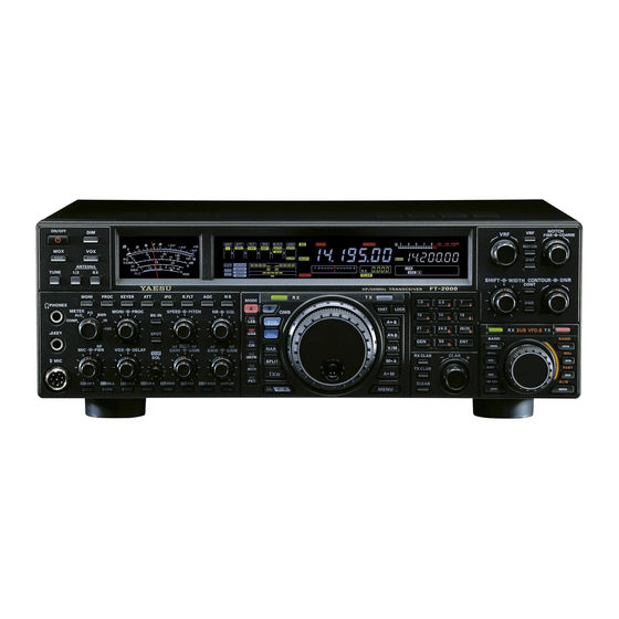
Yaesu FT-2000 Operating Manual
Hf/50 mhz transceiver
Hide thumbs
Also See for FT-2000:
- Technical supplement (206 pages) ,
- Operating manual (140 pages) ,
- Reference book (20 pages)
Table of Contents
Advertisement
Quick Links
HF/50 MH
T
Z
RANSCEIVER
FT-2000
O
M
PERATING
ANUAL
VERTEX STANDARD CO., LTD.
4-8-8 Nakameguro, Meguro-Ku, Tokyo 153-8644, Japan
VERTEX STANDARD
US Headquarters
10900 Walker Street, Cypress, CA 90630, U.S.A.
YAESU EUROPE B.V.
P.O. Box 75525, 1118 ZN Schiphol, The Netherlands
YAESU UK LTD.
Unit 12, Sun Valley Business Park, Winnall Close
Winchester, Hampshire, SO23 0LB, U.K.
VERTEX STANDARD HK LTD.
Unit 5, 20/F., Seaview Centre, 139-141 Hoi Bun Road,
Kwun Tong, Kowloon, Hong Kong
VERTEX STANDARD ( AUSTRALIA ) PTY., LTD.
Normanby Business Park, Unit 14/45 Normanby Road
Notting Hill 3168, Victoria, Australia
Advertisement
Table of Contents

Related Manuals for Yaesu FT-2000


Summary of Contents for Yaesu FT-2000
- Page 1 4-8-8 Nakameguro, Meguro-Ku, Tokyo 153-8644, Japan VERTEX STANDARD US Headquarters 10900 Walker Street, Cypress, CA 90630, U.S.A. YAESU EUROPE B.V. P.O. Box 75525, 1118 ZN Schiphol, The Netherlands YAESU UK LTD. Unit 12, Sun Valley Business Park, Winnall Close Winchester, Hampshire, SO23 0LB, U.K.
- Page 2 The FT-2000 is a leading-edge transceiver with a number of new and exciting features, some of which may be unfamiliar to you. In order to gain the most enjoyment and operating efficiency from your FT-2000, we recommend that you read this manual in its entirety, and keep it handy for reference as you explore the many capabilities of your new transceiver.
-
Page 3: General Description
Congratulations on the purchase of your Yaesu amateur trans- try and Band Change, Speech Processor, IF Monitor for Voice ceiver! Whether this is your first rig, or if Yaesu equipment is modes, CW Pitch control, CW Spot switch, Full CW QSK, already the backbone of your station, rest assured that your adjustable IF Noise Blanker, and all-mode Squelch. -
Page 4: Table Of Contents
Using the UP/DOWN switches of the supplied MH-31B8 Hand Microphone ..49 Receiver Operation (Front End Block Diagram) ... 50 IPO (Intercept Point Optimization) ......51 ATT ................ 51 RF Gain (SSB/CW/AM Modes) ......52 Page 2 FT-2000 O PERATING ANUAL... - Page 5 TX AUDIO Group ..........124 Operation on Alaska Emergency Frequency: TX GNRL Group ..........125 5167.5 kHz (U.S. Version Only) ......100 Specifications ............126 Installation of the Optional Filter (YF-122C & YF-122CN) ......... 128 FT-2000 O Page 3 PERATING ANUAL...
-
Page 6: Accessories & Options
RF μTuning Kit C For 30/20 m Bands FH-2 Remote Control Keypad YF-122C Collins ® CW Filter (500 Hz/2 kHz: –6 dB/–60 dB) YF-122CN ® Collins CW Filter (300 Hz/1 kHz: –6 dB/–60 dB) Page 4 FT-2000 O PERATING ANUAL... -
Page 7: Before You Begin
Always use the 10-Amp fuse in the fuse holder, whether operating on 100 - 120 VAC or 200 - 240 VAC. Change the voltage marking on the label on the rear panel to match the new voltage setting. 200-240 VAC 100-120 VAC FT-2000 O Page 5 PERATING ANUAL... -
Page 8: Extending The Front Feet
Available adjustment range is 120°. Hold the Skirt TIGHTEN LOOSEN Page 6 FT-2000 O PERATING ANUAL... -
Page 9: Resetting The Microprocessor
[ POWER ] switch to turn the transceiver on. Once the transceiver comes on, you may release the [ POWER ] button [ LOCK ] button other two switches. FT-2000 O Page 7 PERATING ANUAL... -
Page 10: Installation And Interconnections
Antenna Tuner may not be able to reduce the impedance mismatch to an acceptable value if the Standing Wave Ratio (SWR) present at the Antenna jack is greater than 3:1. Every effort should, therefore, be made to ensure that the impedance of the antenna system utilized with the FT-2000 be as close as possible to the specified 50-Ohm value. -
Page 11: Grounding
NSTALLATION AND NTERCONNECTIONS ROUNDING The FT-2000 transceiver, like any other HF communications apparatus, requires an effective ground system for maximum electrical safety and best communications effectiveness. A good ground system can contribute to station efficiency in a number of ways: It can minimize the possibility of electrical shock to the operator. -
Page 12: Connection Of Antenna And Power Cables
AC input jack. Be absolutely certain to install your transmitting antenna(s) such that they cannot possibly come in contact with TV/FM radio or other antennas, nor with outside power or telephone lines. Page 10 FT-2000 O PERATING ANUAL... -
Page 13: Connection Of Microphone And Headphone
NSTALLATION AND NTERCONNECTIONS ONNECTION OF ICROPHONE AND EADPHONE FT-2000 O Page 11 PERATING ANUAL... -
Page 14: Key, Keyer, And Computer-Driven Keying
NTERCONNECTIONS The FT-2000 includes a host of features for the CW operator, the functions of which will be detailed in the “Operation” section later. Besides the built-in Electronic Keyer, two key jacks are provided, one each on the front and rear panels, for convenient connection to keying devices. -
Page 15: Vl-1000 Linear Amplifier Interconnections
INEAR MPLIFIER NTERCONNECTIONS Be sure that both the FT-2000 and VL-1000 are turned off, then follow the installation recommendations contained in the illustration. Please refer to the VL-1000 Operating Manual for details regarding amplifier operation. Please do not attempt to connect or disconnect coaxial cables when your hands are wet. -
Page 16: Interfacing To Other Linear Amplifiers
The TX/RX switching in the linear amplifier is con- trolled by switching components in the transceiver. The relay circuit of the FT-2000 used for this switching is capable of switching AC voltage of 100 Volts at up to 300 mA, or DC voltages or 60 V at 200 mA or 30 V at up to 1 Amp. -
Page 17: Plug/Connector Pinout Diagrams
The μ-TUNE, DMU, and PGM connectors are special connectors for this transceiver. Please do not connect any accessory or other device not specifically approved by Vertex Standard. Failure to observe this precaution may cause damage not covered by the Limited Warranty on this apparatus. FT-2000 O Page 15 PERATING... -
Page 18: Front Panel Controls & Switches
POWER Switch TUNE Switch Press and hold in this switch for one second to turn the This is the on/off switch for the FT-2000’s Automatic transceiver on, after first setting the rear panel Antenna Tuner. [ POWER ] switch to the “I” position. Press and hold... -
Page 19: Key Jack
However, if the [ PROC ] knob is advanced This 8-pin jack accepts input from a microphone uti- too far, the increase in compression becomes lizing a traditional YAESU HF-transceiver pinout. counter-productive, as intelligibility will suffer. We recommend that you monitor the sound of your sig- DIM Switch nal using the Monitor (with headphones). - Page 20 RF amplifier ap- pears at the IPO column of the Receiver Configuration Indicator in the display. DVICE The IPO switch affects both the Main (VFO-A) and Sub (VFO-B) receivers. Page 18 FT-2000 O PERATING ANUAL...
- Page 21 Indicates the final amplifier drain voltage. in all modes. It is very useful during local rag-chews, to eliminate noise between incoming transmissions. This control is normally kept fully counter-clockwise (off), except when scanning and during FM operation. FT-2000 O Page 19 PERATING ANUAL...
- Page 22 VOX operation, so the receiver is only ac- put. Adjust this control for the desired power output tivated when your transmission is ended and you wish from the FT-2000. to receive. For CW operation, this knob sets the keying delay,...
- Page 23 [ F5 ( MEM )] key This key is pressed for the purpose of storing either a Voice Memory or a Contest Keyer Memory channel’s contents. See page 72 (Voice Memory) or page 84 (Contest Keyer) for details. FT-2000 O Page 21 PERATING ANUAL...
- Page 24 Pressing the [ A ] or [ B ] button (located above the will be disabled, although the [ SHIFT ] knob still works [ MODE ] selection buttons) will select either the Main normally. band (VFO-A) or Sub band (VFO-B) for individual bandwidth setting. Page 22 FT-2000 O PERATING ANUAL...
- Page 25 If you have tuned off of a Memory chan- nel frequency (MT), pressing this button returns the display to the original memory contents (MR), and pressing it once more returns operation to the Main VFO (no icon). FT-2000 O Page 23 PERATING ANUAL...
- Page 26 What’s more, these keys may be used for direct entry channel to be “masked,” and repeating the process re- of a desired operating frequency during VFO opera- stores the masked memory. tion. Page 24 FT-2000 O PERATING ANUAL...
- Page 27 010 diSP BAR SEL When the optional RF μTuning Kit is connected, this knob allows adjustment of the center frequency of the μ-Tuning filter passband (which is much narrower than that of the VRF). FT-2000 O Page 25 PERATING ANUAL...
- Page 28 [ NOTCH ] knob. DVICE When the [ NAR ] button has been pushed, the [ WIDTH ] knob no longer functions (except the CW mode). The IF SHIFT system is still fully operational, however. Page 26 FT-2000 O PERATING ANUAL...
- Page 29 A) side, and the Red LED imbedded within this button button once more causes the Orange lamp to turn off; will turn off. in this instance, rotation of the [ SUB VFO-B ] knob affects operations associated with the Main band (VFO- FT-2000 O Page 27 PERATING ANUAL...
-
Page 30: Display Indications
If so, you will need to check the condition of the WIDTH antenna, its coaxial cable, and/or the connectors on the Indicates the bandwidth of the DSP IF filter. cable so as to locate and correct the fault. Page 28 FT-2000 O PERATING ANUAL... - Page 31 FAST is activated. This indicator appears when the Main Tuning Dial knob’s tuning rate is selected to fast. This indicator appears when the FT-2000 is in the MIC EQ Memory Recall mode. This indicator appears whenever the Three-Band Para- metric Microphone Equalizer is activated via the Menu.
- Page 32 (VFO-B) receiver’s narrow filter is selected. or Tone Squelch operation, the current tone fre- quency will appear in this area during setup. When activating the CW Spot Tone, the current tone frequency will appear in this area. Page 30 FT-2000 O PERATING ANUAL...
- Page 33 9 for other notes RX ANT “OUT” about proper grounding. RX ANT “IN” μ-TUNE Jacks These jacks are used for signal input/output of the op- tional RF μTuning Kit. FT-2000 O Page 31 PERATING ANUAL...
-
Page 34: Rear Panel
This 5-pin MINI-DIN Jack accepts a cable connected This RCA input jack may be used to provide manual to a YAESU G-800DXA/-1000DXA/-2800DXA An- transmitter activation using a footswitch or other switching device. Its function is identical to the [ MOX ] tenna Rotator (listed models are current as of early 2006). -
Page 35: Key Jack
DMU Jack tion. This 8-pin MINI-DIN jack accepts a cable connected The relay circuit of the FT-2000 used for this jack is to an optional DMU-2000 Data Management Unit. capable of switching AC voltage of 100 Volts at up to... - Page 36 [ POWER ] switch is turned off, then set the rear-panel [ POWER ] switch to the “O” position. Now unplug the AC cable from the rear panel of the transceiver, and wait ten seconds before proceeding with the start-up procedure described below. Page 34 FT-2000 O PERATING ANUAL...
-
Page 37: Basic Operation: Receiving On Amateur Bands
(VFO-A) receiver; the 1.8 and 50 MHz is provided. imbedded LED will glow The FT-2000 utilizes a triple band-stack VFO se- Green. lection technique, which permits you to store up to : : : : : three favorite frequencies and modes onto each... - Page 38 Adjustment of the Sub band (VFO-B) Squelch is accom- plished using the Sub [ SQL ] knob. Page 36 FT-2000 O PERATING ANUAL...
- Page 39 116 tun 116 tun 116 tun DIALSTP,” and “117 tun CW FINE 117 tun CW FINE.” See page 123. DIALSTP DIALSTP 117 tun CW FINE 117 tun CW FINE DIALSTP DIALSTP 117 tun CW FINE FT-2000 O Page 37 PERATING ANUAL...
-
Page 40: (U.s. Version Only)
ETER VERSION ONLY The FT-2000 includes the capability for transmission and reception on the five spot frequencies assigned to the Amateur Service in the United States. To operate on the 5 MHz band: 1. Press the [ V/M ] button once to enter the “Memory”... -
Page 41: Clar (Clarifier) Operation On Main (Vfo-A)
(VFO-B), however). The four small numbers on the Multi-Display Window show the current Clarifier offset. The Clarifier controls on the FT-2000 are designed to allow you to preset an offset (up to ±9.990 kHz) without actually retuning, and then to activate it via the Clarifier’s [ RX CLAR ] and [ TX CLAR ] buttons. This feature is ideal for following a drifting station, or for setting small frequency offsets sometimes utilized in DX “Split”... -
Page 42: Lock
009 diSP DIM VFD” sets the brightness levels of the frequency dis- DIM VFD DIM VFD DIM VFD DIM VFD play (these settings are effective only when the [ DIM ] but- ton is pressed). Page 40 FT-2000 O PERATING ANUAL... - Page 43 OTES FT-2000 O Page 41 PERATING ANUAL...
-
Page 44: Convenience Features
ECEIVE The FT-2000 is capable of simultaneous reception on the same amateur band, using the Main (VFO-A) and Sub (VFO-B) receivers, in what is called the Dual Receive mode. Especially useful for DX work, here is the operating procedure for Dual Receive operation. -
Page 45: Using Headphones For Dual Receive
Although you don’t get the “stereophonic” ef- fect in the monaural mode, the two signals are still mixed, offering the potential for much better copy than in regular AM or even single-sideband ECSS modes. FT-2000 O Page 43 PERATING ANUAL... -
Page 46: Bandwidth Diversity Reception
Adjust the [ AF GAIN ] knob(s) to balance the volume of the two receivers. Now try manipulating the [ SHIFT ] and [ WIDTH ] knobs to observe the interesting effects of bandwidth diversity. Page 44 FT-2000 O PERATING ANUAL... -
Page 47: P.back (Audio Playback) From
ECEIVER Once engaged by the operator, the FT-2000 begins the automatic recording of the last 15 seconds of incoming receiver audio on the Main band (VFO-A). This capability is especially useful for confirming a callsign that may have been difficult to copy due to noise or QRM, etc. -
Page 48: My Bands" Operation
Amateur bands that have not been skipped will appear 14 MHz 7 MHz as you scroll through the bands. 18 MHz 14 MHz 21 MHz 21 MHz 24 MHz 28 MHz 28 MHz 50 MHz Page 46 FT-2000 O PERATING ANUAL... -
Page 49: Band Stack Operation
PERATION The FT-2000 utilizes a triple band-stack VFO selection technique, that permits you to store up to three favorite frequencies and modes onto each band’s VFO register. For example, you may store one frequency each on 14 MHz CW, RTTY, and USB, then recall these VFOs by successive, momentary presses of the [ 14 ] MHz band button. -
Page 50: Rotator Control Functions
ONTROL UNCTIONS When using a YAESU model G-800DXA, G-1000DXA, or G-2800DXA rotator (not supplied), it is possible to control it from the front panel of the FT-2000. 1 Press and hold in the [ ENT ] button (one of the [ BAND ] button) for two seconds. -
Page 51: More Frequency Navigation Techniques
4. Press the [ ENT ] button once more. A short “beep” will confirm that the frequency entry was successful, and the new operating frequency will appear on the Sub (VFO-B) frequency display fields. FT-2000 O Page 49 PERATING ANUAL... -
Page 52: Receiver Operation (Front End Block Diagram)
LOCK IAGRAM The FT-2000 includes a wide range of special features to suppress the many types of interference that may be encountered on the HF bands. However, real world interference conditions are constantly changing, so optimum setting of the controls is somewhat of an art, requiring familiarity with the types of interference and the subtle effects of some of the controls. -
Page 53: Ipo (Intercept Point Optimization)
IPO should be disabled and the [ ATT ] button should be set to “OFF OFF.” This situation is typical during quiet times on frequencies above 21 MHz, and when using a small or negative-gain receiving antenna on other bands. FT-2000 O Page 51 PERATING... -
Page 54: Rf Gain (Ssb/Cw/Am Modes)
Thereafter, the RF Gain and Attenuator fea- tures may be employed to provide precise, delicate adjustment of the receiver gain so as to optimize per- formance fully. Page 52 FT-2000 O PERATING ANUAL... -
Page 55: Rf Front End
DX-pedition. The FT-2000’s VRF system affects the 1.8 - 28 MHz amateur bands only. 1. Press the [ VRF ] button momentarily. The “... -
Page 56: Interference Rejection (Signals Off Frequency By Just A Few Khz)
A “Roofing Filter,” as its name implies, places a “Roof” over the receiver’s IF system bandwidth. This “Roof” pro- tects the circuitry downstream from the first mixer from interference, just as a roof on a house protects the contents from rain and snow. Page 54 FT-2000 O PERATING ANUAL... -
Page 57: Interference Rejection (Signals Within 3 Khz)
Contour filter, the “shoulder” of the passband response may be altered, or components removed from within the passband, allowing the desired signal to rise above the background noise and interference in a manner not obtainable with other filtering systems. FT-2000 O Page 55 PERATING... -
Page 58: If Shift Operation
[ SHIFT ] knob so as to reduce the in- terference level by moving the filter passband so that the interference is outside of the passband. Desired Signal Desired Signal Desired Signal BANDWIDTH BANDWIDTH BANDWIDTH Page 56 FT-2000 O PERATING ANUAL... -
Page 59: Width (If Dsp Bandwidth) Tuning
CW Mode: 25 Hz ~ 2.4 kHz (2.4 kHz ) RTTY/PKT Modes: 25 Hz ~ 2.4 kHz (500 Hz ) : bandwidth at 12 o’clock position of [ WIDTH ] knob. BANDWIDTH BANDWIDTH BANDWIDTH FT-2000 O Page 57 PERATING ANUAL... -
Page 60: If Notch Filter Operation
The tuning rate for the IF (Heterodyne) (Heterodyne) Notch is somewhat slow while you adjust the [ FINE ] knob, so the use of the Waterfall display to confirm proper adjustment is highly recommended. BANDWIDTH BANDWIDTH Page 58 FT-2000 O PERATING ANUAL... -
Page 61: Digital Noise Reduction (Dnr) Operation
2. To cancel DNF operation, press the [ DNF ] button once more. The “ ” icon will turn off, confirming that the Digital Notch Filter is no longer in operation. DVICE The Digital Notch Filter affects the Main (VFO-A) band only. FT-2000 O Page 59 PERATING ANUAL... -
Page 62: Narrow (Nar) One-Touch If Filter Selection
When you press the [ NAR ] button in the FM mode, both the transmit and receive bandwidths are narrowed. When the [ NAR ] button is pressed, the [ WIDTH ] knob no longer functions (except the CW mode). Page 60 FT-2000 O PERATING ANUAL... -
Page 63: If Noise Blanker (Nb) Operation
IF N OISE LANKER PERATION The FT-2000 includes an effective IF Noise Blanker, which can significantly reduce noise caused by automotive ignition systems. Main band ( VFO-A ) NB Operation Main Band ( VFO-A ) “NB” Icon [ NB ] Button Sub Band ( VFO-B ) “NB”... -
Page 64: Tools For Comfortable And Effective Reception
SLOW erally do not recommend any changes to the AGC Menu SLOW selections until you are thoroughly familiar with the per- FAST FAST formance of the FT-2000. FAST RTTY SLOW ERMINOLOGY PKT ( FM ) FAST... -
Page 65: Sloped Agc Operation
In traditional AGC systems, the audio output from the transceiver becomes essentially fixed once the threshold for AGC action is reached (usually several dozen dB above the no-signal noise SLOPED floor). The FT-2000, however, includes an innovative Sloped AGC system on the Main band (VFO-A) receiver, that allows the audio volume to rise NORMAL and fall slightly according to signal strength. -
Page 66: Ssb/Am Mode Transmission
ALC meter deflects. In many cases, the same setting as used on SSB will be satisfactory. 5. Release the PTT switch at the end of your transmis- sion. The transceiver will return to the receive mode. Page 64 FT-2000 O PERATING ANUAL... - Page 67 [ MIC ] (gain) knob. Therefore, we recom- trol are provided on the FT-2000, and you may choose mend that you make [ MIC ] knob adjustments into a the technique(s) that best suit your operating needs: Pressing the microphone’s PTT switch will engage...
-
Page 68: Using The Automatic Antenna Tuner
UNER The Automatic Antenna Tuner (hereinafter referred to as the “ATU”) built into each FT-2000 is crafted to ensure a 50-Ohm load for the final amplifier stage of the transmitter. We recommend that the ATU be used whenever you operate on the FT- 2000. -
Page 69: About Atu Operation
SWR (Post-tuning) Greater than 3:1 The “ ” icon will light up, and tuning settings, if achieved, will not be memorized. Please investigate and resolve the high SWR condition before attempting further operation using this antenna. FT-2000 O Page 67 PERATING ANUAL... -
Page 70: Lithium Battery Replacement
The exhaustion of the ATU backup battery of the FT-2000 is a normal “wear and tear” situation, and the loss of the backup voltage is not a “defect” or other condition covered by the Limited Warranty on this product. Accordingly, if you do not feel capable of replacing the battery, and ask a service shop to do so on your behalf, a service fee may apply. -
Page 71: Enhancing Transmit Signal Quality
Speech Processor is engaged. When the optional DMU-2000 Data Management Unit is connected, you may observe the effect of your com- pression level adjustments by viewing the wave-form on the “Oscilloscope” page. FT-2000 O Page 69 PERATING ANUAL... -
Page 72: Adjusting The Ssb Transmitted Bandwidth
Audio Scope on the “Oscilloscope” page. bandwidth, and the power detection circuitry does not compensate for the effect of the bandwidth selection (it is calibrated in the default 2.4 kHz bandwidth). Page 70 FT-2000 O PERATING ANUAL... -
Page 73: Parametric Microphone Equalizer
ICROPHONE ODES The FT-2000 includes a unique Three-Band Parametric Microphone Equalizer, that provides precise, independent control over the low-, mid-, and treble-ranges in your voice wave-form. You may utilize one group of settings for when the speech processor is off, and an independent group of settings for when the speech processor is on. -
Page 74: Transmitter Convenience Features
ODES You may utilize the Voice Memory capability of the FT-2000 for repetitive messages. The Voice Memory system includes four memories capable of storing up to 20 seconds of voice audio each. The maximum that any memory can hold is 20 seconds. -
Page 75: Voice Memory Operation From The Optional Fh-2 Remote Control Keypad
ODES Voice Memory Operation from the optional FH-2 Remote Control Keypad You may also utilize the Voice Memory capability of the FT-2000 from the optional FH-2 Remote Control Keypad which plugs into the rear panel’s REM jack. When using the FH-2 Remote Control Keypad, you may record five memories with up to 20 seconds of voice audio each. -
Page 76: Vox (Automatic Tx/Rx Switching Using Voice Control)
IF signal, it can be very useful for check- ing the adjustment of the Speech Processor or Para- metric Equalizer on SSB, and for checking the general signal quality on AM and FM. Page 74 FT-2000 O PERATING ANUAL... -
Page 77: Split Operation Using The Tx Clarifier
Yaesu transceivers with capa- the small display window. bility similar to that of your FT-2000. On the DX side of As with receiver Clarifier operation, when you turn the the pile-up, everyone calling precisely on the same CW... -
Page 78: Split-Frequency Operation
REQUENCY PERATION A powerful capability of the FT-2000 is its flexibility in Split Frequency operation, using the Main (VFO-A) and Sub (VFO-B) frequency registers. This makes the FT-2000 especially useful for high-level DX-pedition use, as the Split opera- tion capability is very advanced and easy to use. -
Page 79: Quick Split Operation
[ SUB VFO-B ] Knob Main Tuning Dial Knob save the new setting and exit to normal operation. If you only press the [ MENU ] button momentarily to exit, any changes you performed will not be stored. FT-2000 O Page 77 PERATING ANUAL... -
Page 80: Cw Mode Operation
CW M PERATION The powerful CW operating capabilities of the FT-2000 include operation using both an electronic keyer paddle and a “straight key” or emulation thereof, as is provided by a computer-based keying device. ETUP FOR TRAIGHT TRAIGHT EY EMULATION... -
Page 81: Using The Built-In Electronic Keyer
[ SPEED ] knob while pressing the [ KEYER ] Full Break-in (QSK) Operation button. The Sub (VFO-B) frequency display shows As shipped from the factory, the FT-2000 TX/RX the keying speed. system for CW is configured for “Semi-break-in”... -
Page 82: Setting The Keyer Weight
The configuration of the Electronic Keyer may be customized independently for the front and rear KEY jacks of the FT-2000. This permits utilization of Automatic Character Spacing (ACS), if desired, as well as the use of the electronic keyer via the front jack and a straight key or computer-driven keying line via the rear panel. -
Page 83: Cw Convenience Features
DX station. From the DX side, if a dozen or more operators (also using Yaesu’s SPOT system) all call precisely on the same frequency, their dots and dashes merge into a single, long tone... -
Page 84: Using Cw Reverse
When the incoming signal pitch tone is properly aligned, the central red marker lights up whether or not CW Reverse is engaged. RX Passband Retune: Shift to Lower Frequency CW Reverse Carrier Zero-In Retune: Shift to Higher Frequency RX Passband Page 82 FT-2000 O PERATING ANUAL... -
Page 85: Cw Delay Time Setting
Hz (typically), so as to allow your ear to detect the tone. The BFO offset associated with this tun- ing (that produces the comfortable audio tone) is called the CW Pitch. FT-2000 O Page 83 PERATING ANUAL... -
Page 86: Contest Memory Keyer
EMORY EYER The FT-2000 in capable of the automatic sending of CW messages (as you might do in a contest). Two techniques for message storage are available: you may either send the desired message contents using your keyer paddle (“Message Memory”), or you may input the text characters using the Main Dial Tuning knob and [ SUB VFO-B ] knobs (“Text... -
Page 87: Transmitting In The Beacon Mode
Menu item to “off.” Press the [ F1 ( CH1 )] ~ [ F4 ( CH-4 )] button, depending on the register into which the Beacon message is stored. Repetitive transmission of the Beacon message will begin. Press one of these keys once more to halt the Beacon transmissions. FT-2000 O Page 85 PERATING... -
Page 88: Text Memory
Use the Main Tuning Dial knob to select the last correct letter in the message. Now rotate the [ SUB VFO-B ] knob to select the “}” character; everything after the “}” charac- ter will be deleted. Page 86 FT-2000 O PERATING ANUAL... -
Page 89: Contest Number Programming
\ \ \ \ \ < % % % % % , , , , , = = = = = ^ ^ ^ ^ ^ & > _ _ _ _ _ ‘’’ ‘}’ FT-2000 O Page 87 PERATING ANUAL... -
Page 90: Contest Memory Keyer (Using The Optional Fh-2 Remote Control Keypad)
EMOTE ONTROL EYPAD You may also utilize the CW message capability of the FT-2000 from the optional FH-2 Remote Control Keypad, which plugs into the rear panel’s REM jack. Message Memory Five memory channels capable of retaining 50 characters total are provided (using the PARIS standard for characters and word length). - Page 91 052 A1A F-TYPE 052 A1A F-TYPE 052 A1A F-TYPE 054 A1A 054 A1A 054 A1A 054 A1A R-TYPE” to “ACS ACS” (Automatic Character Spacing) while R-TYPE R-TYPE R-TYPE R-TYPE you are programming the keyer memories. FT-2000 O Page 89 PERATING ANUAL...
-
Page 92: Text Memory
Current Cursor Position Cursor gram the text. LOCK CW Memory Register Number Message DVICE You may also use the Main Tuning Dial knob and the [ SUB VFO-B ] knobs to program the message charac- ters. Page 90 FT-2000 O PERATING ANUAL... - Page 93 (the Menu Mode Setting By pressing the FH-2’s [ DEC ] key momentarily, is set to “tyP2 tyP2 tyP2 tyP2 tyP2”). you may reduce the current Contest Number by one. LOCK FT-2000 O Page 91 PERATING ANUAL...
-
Page 94: Fm Mode Operation
FM is only used in the 28 MHz and 50 MHz Amateur bands covered in the FT-2000. Please do not use FM on any other bands. Page 92... -
Page 95: Repeater Operation
FM M PERATION EPEATER PERATION The FT-2000 may be utilized on 29 MHz and 50 MHz repeaters. 1. Rotate the Main Tuning Dial knob to the output fre- [ MOX ] Button [ AM/FM ] Button quency (downlink) from the repeater. -
Page 96: Memory Operation
UICK OINT The FT-2000’s memory channels store the following data (not just the operating frequency): Frequency Mode Clarifier status and its Offset Frequency... -
Page 97: Qmb (Quick Memory Bank)
If you do not over-write the contents of the current memory channel, the original contents will not be disturbed by the initiation of Memory Tune operation. FT-2000 O Page 95 PERATING ANUAL... -
Page 98: Standard Memory Operation
PERATION The Standard Memory of the FT-2000 allows storage and recall of up to 99 memories, each storing frequency, mode, and a wide variety of status information detailed previously. Memories may be grouped into as many as six Memory Groups, and additionally you get nine pairs of band-limit (PMS) memories along with five QMB (Quick Memory Bank) memories. -
Page 99: Checking A Memory Channel's Status
After erasure, only the memory channel number will remain; the frequency data will disappear from the dis- play. If you make a mistake and wish to restore the memory’s contents, just repeat steps (1) through (3) above. FT-2000 O Page 97 PERATING ANUAL... -
Page 100: Moving Memory Data To
Because the “Memory Tune” mode so closely resembles the VFO mode, be sure that you have the FT-2000 operating in a control mode compatible with your software’s requirements. Use the VFO mode if you’re not sure. -
Page 101: Memory Groups
[ GRP ] or [ M CH ] button again. If no channels have been assigned to a particular Memory Group, you will not have access to that Group. FT-2000 O Page 99 PERATING... -
Page 102: Operation On Alaska Emergency Frequency
The FT-2000 includes the capability for transmission and reception on 5167.5 kHz under such emergency conditions via the Menu system. To activate this feature: 1. -
Page 103: Vfo And Memory Scanning
EMORY CANNING You may scan wither the VFO or the memories of the FT-2000, and the radio will halt the scan on any station with a signal strong enough to open the receiver’s squelch. VFO S CANNING 1. Set the VFO to the frequency on which you would like to begin scanning. -
Page 104: Memory Scan
039 GEnE SCN RSM 5Sec will cause the scanner to resume scanning after five seconds; you may change it, however, to resume only after the carrier has dropped out, if you like See page 115. Page 102 FT-2000 O PERATING ANUAL... -
Page 105: Pms
9. If you press the microphone’s PTT switch during scan- ning, the scanner will halt at once. Pressing the PTT switch during scanning will not cause transmission, however. FT-2000 O Page 103 PERATING ANUAL... -
Page 106: Packet Operation
ACKET PERATION Packet operation is easily accomplished on the FT-2000 by connecting your TNC (Terminal Node Controller) to the transceiver, per the illustration. “Packet” operation also applies to SSB-based AFSK data modes, such as PSK31, etc. DATA DATA PACKET ②... -
Page 107: Rtty (Radio Teletype) Operation
OINT a few minutes, we recommend that you use the [ RF PWR ] In the FT-2000, “RTTY” is a mode defined as being an knob to reduce the transmitter power to 1/2 ~ 1/3 of its “FSK” mode, whereby the closing and opening of a key- normal maximum. -
Page 108: Miscellaneous Afsk-Based Data Modes
AFSK-B ISCELLANEOUS ASED ODES The FT-2000 may also be used for a host of other SSB-based Data modes. Please set up your system using the illustration as a guideline. LINE IN or MIC IN LINE OUT or MIC OUT COM PORT PACKET ②... -
Page 109: About The Transverter Output Terminal
You may set up the frequency display so that it shows the actual band on which your transverter is operating (instead of the “IF” used by the transverter, which is the 28 MHz band on your FT-2000). Example: Setting up the FT-2000 display for use with a 144 MHz Transverter 1. -
Page 110: Menu Mode
The Menu system of the FT-2000 provides extensive customization capability, so you can set up your transceiver just the way you want to operate it. The Menu items are grouped by general utilization category, and are numbered from “001 AGc... - Page 111 050 A3E MICGAIN Ur/0 ~ 100 MODE-AM 051 A3E MIC SEL Frnt/dAtA/PC Frnt MODE-CW 052 A1A F-TYPE OFF/buG/ELE/ACS MODE-CW 053 A1A F-REV nor/rEU MODE-CW 054 A1A R-TYPE OFF/buG/ELE/ACS 1: Requires optional DMU-2000 Data Management Unit. FT-2000 O Page 109 PERATING ANUAL...
- Page 112 950/2100/2250 Hz SCOPE 105 SCP 1.8 FI 1.800 - 1.999 MHz (1 kHz/step) 1.800 MHz SCOPE 106 SCP 3.5 FI 3.500 - 3.999 MHz (1 kHz/step) 3.500 MHz 1: Requires optional DMU-2000 Data Management Unit. Page 110 FT-2000 O PERATING ANUAL...
- Page 113 TX GNRL 146 tGEn VOX SEL nic/dAtA TX GNRL 147 tGEn EMRGNCY EnA(ENABLE)/diS(DISABLE) diS(DISABLE) 1: Requires optional DMU-2000 Data Management Unit. 2: This Menu item does not work. Please do not change this setting. FT-2000 O Page 111 PERATING ANUAL...
-
Page 114: Agc Group
Default Setting: 0 ° 013 diSP RTR ADJ Function: Adjusts the indicator needle precisely to the starting point set in menu item “012 diSP RTR STU.” Available Values: –30 ~ 0 Default Setting: 0 Page 112 FT-2000 O PERATING ANUAL... -
Page 115: Dvs Group
Function: Permits entry of the CW message for message register 2. Available Values: tyP1/tyP2 Default Setting: tyP2 tyP1: You may enter the CW message from the front panel’s Function Keys. tyP2: You may enter the CW message from the CW keyer. FT-2000 O Page 113 PERATING ANUAL... -
Page 116: General Group
Available Values: On/OFF Default Setting: OFF 031 GEnE Q SPLIT Function: Selects the tuning offset for the Quick Split fea- ture. Available Values: –20 ~ 0 ~ +20 kHz (1 kHz Step) Default Setting: +5 kHz Page 114 FT-2000 O PERATING ANUAL... - Page 117 Do not perform this Menu item unless you have a high- justment has no effect. performance frequency counter. Perform this Menu item after aging the transceiver and frequency counter suffi- ciently (at least 30 minutes). FT-2000 O Page 115 PERATING ANUAL...
-
Page 118: S If Sft Group
Default Setting: 0 Hz 049 S-iF PKT-USB Function: Sets the center frequency of the Sub band (VFO- B) receiver’s IF filter in the Packet (USB) mode. Available Values: –1000 ~ +1000 Hz Default Setting: 0 Hz Page 116 FT-2000 O PERATING ANUAL... -
Page 119: Mode-Cw Group
Default Setting: nor tronic keyer. nor: Tip = Dot, Ring = Dash, Shaft = Ground Available Values: (1:) 2.5 ~ 4.5 rEU: Tip = Dash, Ring = Dot, Shaft = Ground Default Setting: 3.0 FT-2000 O Page 117 PERATING ANUAL... -
Page 120: Mode-Dat Group
Available: –3000 ~ +3000 Hz (10 Hz/step) Default: 0 Hz 071 dAtA PKT SFT Function: Sets the carrier point during the SSB packet operation. Available: –3000 ~ +3000 Hz (10 Hz/step) Default: 1000 Hz (typical center frequency for PSK31, etc.) Page 118 FT-2000 O PERATING ANUAL... -
Page 121: Mode-Fm Group
Function: Sets the magnitude of the repeater shift on the 50 MHz band. Function: Selects the Mark tone for RTTY operation. Available Values: 0 ~ 4000 kHz (10 kHz/step) Available Values: 1275/2125 Hz Default Setting: 1000 kHz Default Setting: 2125 Hz FT-2000 O Page 119 PERATING ANUAL... -
Page 122: Mode-Ssb Group
Available Values: –200 Hz ~ +200 Hz (10 Hz/step) Default Setting: 0 Hz 087 J3E SUSB CR Function: Adjusts the receiver carrier point for Sub band’s (VFO-B) USB mode. Available Values: –200 Hz ~ +200 Hz (10 Hz/step) Default Setting: 0 Hz Page 120 FT-2000 O PERATING ANUAL... -
Page 123: Rx Dsp Group
Default Setting: 300 Hz Default Setting: nEd (MEDIUM) 095 rdSP CW NARR Function: Selects the passband of the DSP filter for the CW “Narrow” mode. Available Values: 25/50/100/200/300/400/500/800/1200/ 1400/1700/2000 Hz Default Setting: 500 Hz FT-2000 O Page 121 PERATING ANUAL... -
Page 124: Scope Group
GENTLE Spectrum Scope while monitoring on the 30 m amateur band. DSP F ILTER ASSBAND Available Values: (1)0.100 - (1)0.149 MHz (1 kHz steps) Default Setting: (1)0.100 MHz SHARP SOFT DSP F ILTER HAPE Page 122 FT-2000 O PERATING ANUAL... -
Page 125: Tuning Group
“ON” (a “d d d d d ” notation will replace the “E E E E E ” notation). Repeat the same procedures to cancel the setting (skipped “Off”: “d d d d d ” notation appears). FT-2000 O Page 123 PERATING... -
Page 126: Tx Audio Group
Available Values: 1 ~ 10 Function: Adjusts the Q-factor of the low range of the Default Setting: 10 parametric microphone equalizer when the speech proces- sor is activated. Available Values: 1 ~ 10 Default Setting: 2 Page 124 FT-2000 O PERATING ANUAL... -
Page 127: Tx Gnrl Group
The use of this frequency is restricted to stations operat- Available Values: 1 ~ 10 ing in or near Alaska, and only for emergency purposes Default Setting: 1 (never for routine operations). See §97.401(c) of the FCC’s regulations for details. FT-2000 O Page 125 PERATING ANUAL... -
Page 128: Specifications
At least 60 dB below peak output Audio Response (SSB): Not more than –6 dB from 300 to 2700 Hz 3rd-order IMD: –31 dB @14 MHz 100 watts PEP Microphone Impedance: 600 Ohms (200 to 10 kOhms) Page 126 FT-2000 O PERATING ANUAL... - Page 129 4 to 8 Ohms (4 Ohms: nominal) Conducted Radiation: Less than 4000 μμW Specifications are subject to change, in the interest of technical improvement, without notice or obligation, and are guaranteed only within the amateur bands. FT-2000 O Page 127 PERATING ANUAL...
-
Page 130: Installation Of The Optional Filter
(“300 300” for YF-122CN, “500 500” for YF-122C). 12. Press and hold in the [ MENU ] button for two seconds RX-2 UNIT to save the new setting and exit to normal operation. IGURE Page 128 FT-2000 O PERATING ANUAL... - Page 131 This equipment has been tested and found to comply with the limits for a Class B digital device, pursuant to Part 15 of the FCC Rules. These limits are designed to provide reasonable protection against harmful interference in a residential installation. This equipment generates, uses and can radiate radio frequency energy and, if not installed and used in accordance with the instructions, may cause harmful interference to radio communications.
- Page 132 Copyright 2007 Printed in Japan VERTEX STANDARD CO., LTD. 0710P-EY All rights reserved No portion of this manual may be reproduced without the permission of VERTEX STANDARD CO., LTD.