Olympus DP21-SAL Instructions Manual
Standalone connection kit
Hide thumbs
Also See for DP21-SAL:
- Quick operation manual (2 pages) ,
- Quick operation manual (2 pages)
Table of Contents
Advertisement
Quick Links
INSTRUCTIONS
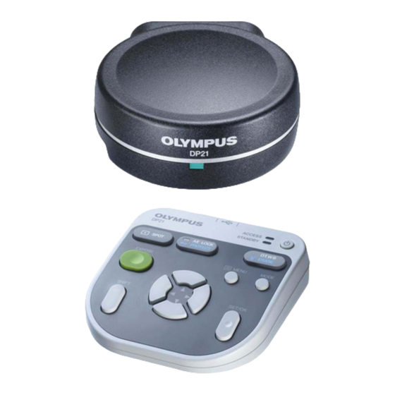
DP21-SAL
STANDALONE CONNECTION KIT
This instruction manual is for the Olympus standalone connection kit DP21-SAL for use in the control
of microscope digital camera. To ensure the safety, obtain optimum performance and familiarize
yourself fully with the use of this device, we recommend that you study this manual thoroughly before
operating the camera.
Retain this instruction manual in an easily accessible place near the work desk for future reference.
A X 8 2 3 3
Downloaded from
ManualsNet.com
search engine
Advertisement
Table of Contents

Related Manuals for Olympus DP21-SAL


Summary of Contents for Olympus DP21-SAL
- Page 1 DP21-SAL STANDALONE CONNECTION KIT This instruction manual is for the Olympus standalone connection kit DP21-SAL for use in the control of microscope digital camera. To ensure the safety, obtain optimum performance and familiarize yourself fully with the use of this device, we recommend that you study this manual thoroughly before operating the camera.
- Page 2 Refer to your local Olympus distributor in EU for return and/or collection systems available in your country. NOTE: This equipment has been tested and found to comply with the limits for a Class A digital device, pursuant to Part 15 of the FCC Rules.
-
Page 3: Table Of Contents
CONTENTS IMPORTANT SYSTEM CHART MODULE NOMENCLATURE 8-11 2-1 Hardware controls ..................................8,9 2-2 MENU / INFO display ................................10, 1 1 INSTALLATION 12-16 BASIC IMAGE RECORDING PROCEDURE 17-25 RECORDING FUNCTION SETTING / OPERATION (REC) 26-51 5-1 Operation using the hand switch D21-HS ..................26-29 5-2 Operation using the MENU display ...................... -
Page 4: Important
DP21/DP26 in a stand-alone mode. Descriptions in Instruction Manual This Instruction Manual contains only the descriptions of Stand-alone Connection Kit DP21-SAL. For procedures to use the microscope digital camera, refer to the Instruction Manual of the relevant microscope digital camera. - Page 5 2. When connecting a cable or power cord, push in the connector all the way before pressing the main switch to ON. 3. Always use the power cord and AC adapter provided by Olympus. If no power cord is provided, please select the proper power cord by referring to the section “PROPER SELECTION OF THE POWER CORD”...
- Page 6 1. This device is a precision instrument. Handle it with care and avoid subjecting it to sudden or severe impact. 2. If the standalone connection kit DP21-SAL is used in a manner not specified by this manual, the safety of the user may be imperiled.
- Page 7 Image Data Storage 1. The recorded image data may be lost (destroyed) in the following cases. Note that Olympus will not assume any liabilities for the loss (destruction) of recorded data. The image data may also be destroyed by an unexpected cause.
- Page 8 · If malfunction or a symptom of infection still persists after the above measure, please consult Olympus. Olympus will not assume any liabilities for a malfunction of the DP21-SAL due to computer viruses as well as any trouble or damage of the user’s PC or network incurred due to computer viruses.
- Page 9 7. The measurement results are simply superimposed on the image and no text file or like is created. 8. The DP21-SAL can handle files of the FAT and FAT32 formats only, and it is not compatible with other file formats.
-
Page 10: System Chart
Camera adapter Hand Switch D21-HS Mouse }Image color setup matching the microscope is required for faithful color reproduction (see page 37 for details). }Consult Olympus for the microscope and camera adapter to be used together. Downloaded from ManualsNet.com search engine... -
Page 11: Module Nomenclature
DP21-SAL MODULE NOMENCLATURE 2-1 Hardware controls Control Box D21-CB Front view Pilot LED Main switch USB ports LAN cable connector Rear view DC IN connector Display connector DVI-I/-D/-A RS232C connector Camera cable connector For connection of the USB ports control box (U-CBS, etc.) - Page 12 Control box Camera Cable D21-CB Camera head 1394b connector (9-pin) Stabilizer for Vertical DVI Protection Adapter Installation Stabilizer With 2 clamp screws AC adapter Power output plug Input connector Downloaded from ManualsNet.com search engine...
-
Page 13: Menu / Info Display
DP21-SAL 2-2 MENU / INFO display The screens shown below are those displayed when combined with DP21. When combined with DP26, the screen displayed may be partially different, but the basic functions stay the same. For details, refer to the description of each function. - Page 14 INFO display (PLAY) Recorded folder White balance (p. 35) Image No. name (p. 57) File name (p. 36) ISO speed (p. 32) Image quality Date / Time (p. 31) (p. 56) Exposure time Metering area Exposure Protect (p. 55) Zoom (p. 28) (p.
-
Page 15: Installation
DP21-SAL INSTALLATION This section describes only the procedures to mount the control box D21-CB. For detail descriptions of the microscope, the camera head or the camera adapter, etc. to be used together, refer to the relevant Instruction Manual, and assemble them with careful attention. - Page 16 Connecting the AC Adapter (Fig. 4) CAUTION · Always use the AC adapter provided by Olympus. Using other AC adapter will result in malfunction or damage. · The cords and cables are vulnerable to bend or twist. Do not ³...
- Page 17 Otherwise, a failure of the control box D21-CB, camera head or power supply, or an incident including a fire hazard may result. Note that Olympus will not warrant damage incurred due to the use of a non- designated AC adapter.
- Page 18 If you use a commercially available USB memory, connect it to a USB port of the control box D21-CB. The USB memory provided with the DP21-SAL can also be used by inserting it into a USB port of the control box D21-CB.
- Page 19 }It is not possible to install a special driver for the mouse or keyboard in the DP21-SAL. As a result, if a device requires a special driver, only the standard functions of the device are available with the DP21-SAL.
-
Page 20: Basic Image Recording Procedure
BASIC IMAGE RECORDING PROCEDURE This section describes the basic operating procedure of the microscope digital camera (from turning power ON to image recording) and the initial setting method. The information in this section is enough for mastering the basic method for recording still images and movies. Operation flow }Perform the optical adjustments sufficiently before proceeding to the following. - Page 21 DP21-SAL Turning Power ON/OFF Turning power ON 1) Set the main switch of the camera head to “ I ” (ON). 2) Press the main switch @ of the control box D21-CB to turn it ON. Fig. 9 Turning power OFF Press the main switch ²...
- Page 22 Initial Setting To use the system correctly, it is required to set the language and scale magnification at the beginning. Set them by following the window displayed when the system is turned ON for the first time. }The setting window is not displayed the next time the system is turned ON.
- Page 23 DP21-SAL Selecting the Mode The MODE button @ can be used to select the REC AUTO (auto-expo- sure recording), REC MANUAL (manual-exposure recording) or PLAY (play- back) mode. }When the power is turned ON and the REC AUTO or REC MANUAL mode is selected, the live image is displayed on the monitor screen.
- Page 24 Viewing/Controlling the MENU Display 1. Press the MENU button @ to view or hide the MENU display alternately. For details on the MENU display items, see MENU display (p. 10). The MENU display is hidden with the default setting. 2. Press the cursor buttons ² to select an item and press the SET button ³ to enter the selection.
- Page 25 DP21-SAL DP21 Setting the Live Resolution You can select the live image resolution. DP21 DP26 High resolution 1600 x 1200 2448 x 1920 Frame rate: 15fps Frame rate: 7fps Low resolution 800 x 600 1224 x 960 Frame rate: 27fps...
- Page 26 OTWB (One-Touch White Balance) Adjust the white balance before recording to record image in optimum color tones. 1. Display an exclusively white live image. · During transmitted light observation, remove the specimen. · During reflected light observation, set a piece of white paper in place of the specimen.
- Page 27 DP21-SAL Recording Still Images ² 1. On the microscope, frame the image to be recorded and focus on it. To facilitate focusing, use the zoom display of the live image (p. 28) or display the focusing indicator (p. 40). 2. Press the EXPOSE button @ to record the still image, which is saved in the USB memory connected to the control box D21-CB or hand switch D21-HS.
- Page 28 Recording Movies 1. On the microscope, frame the image to be recorded and focus on it. 2. While holding the SHIFT button @, press the EXPOSE button ² to start movie recording. 3. To stop movie recording, press the EXPOSE button ². The movie is saved in the USB memory.
-
Page 29: Recording Function Setting / Operation (Rec)
DP21-SAL RECORDING FUNCTION SETTING / OPERATION (REC) 5-1 Operation using the hand switch D21-HS This section describes the method of operating the basic functions using the hand switch D21-HS. The hand switch D21- HS has buttons to which the functions frequently used in microscope observation are assigned to facilitate the recording of clear images. - Page 30 Exposure Adjustment REC AUTO mode The exposure time set by AE (Auto Exposure) can be corrected (by up to 2 EV in 1/3 EV steps). When the specimen is dark, +EV correction will extend the exposure time and give an over-exposure type effect. When it is bright, the -EV correc- tion will shorten the exposure time and give an under-exposure type effect.
- Page 31 DP21-SAL AE Lock Setting REC AUTO mode only 1. Press the AE LOCK button @ to lock the current exposure time. The AE LOCK LED ² lights and the INFO display shows the locked exposure time. 2. Press the AE LOCK button @ again to cancel AE LOCK.
- Page 32 Composite Button Operations Pressing two buttons makes it possible to perform a quick setting as shown in the following table (¦: Possible / Impossible). To perform this, ensure that the MENU display is hidden, hold the “Held button” and press the “Switching button.”...
-
Page 33: Operation Using The Menu Display
DP21-SAL 5-2 Operation using the MENU display This section describes the operation method of the functions that are available in the MENU display on the monitor screen. This section pertains to the recording operation (in the REC AUTO/REC MANUAL modes). See page 21 for the basic operations and flow of the MENU display. - Page 34 Default (DP21): HQ Image Quality Mode Setting Default (DP26): 2448 x 1920, JPEG-LOW Image quality DP21 }Select the quality of the recorded image. The image quality improves as the setting is advanced from “SQ-H” -- > “SQ-L” -- > “HQ” -- > “SHQ” -- > “TIFF.” Image quality mode Compression rate Save format...
- Page 35 DP21-SAL ISO Speed Setting Default: 100 }Select the sensitivity (ISO speed) in image capturing. The figures are set based on the ISO speeds of photo films. Three options of 100, 200 and 400 are available. The larger ISO speed is more suitable for recording of dark specimens or quickly-moving objects.
- Page 36 Save Folder Setting Default: AUTO When more than one DP21/DP26 unit records and saves images into the Setting the save folder ² same folder in a network PC, etc. at the same timing, an error about the impossibility of saving the recorded images may occur. Wait a while and retry recording the images or save the image files in different folders.
- Page 37 DP21-SAL Specifying the save folder by the address The save destination can be specified by entering the folder address. In addition, a pull-down menu is also available listing the recently-specified addresses (up to 10 addresses) so that the user can also select the desired address from them.
- Page 38 White Balance (WB) Mode Setting Default: AUTO The white balance adjustment mode can be selected from the DP21 following three options. DP26 Mode Function/Characteristics AUTO Identifies the white part in the live image and adjusts the white balance automatically. The white balance adjustment is executed automatically whenever the illumination brightness changes.
- Page 39 DP21-SAL Folder and File Names When an image is recorded, the DP21/DP26 automatically creates a folder in the image save destination and saves the image file in it. The folder and file names are created automatically as shown below. Folder and file names Each image recorded with the DP21/DP26 is automatically given the folder and file names as shown below.
-
Page 40: Applied Operation
5-3 Applied Operation This section describes the applied functions of the DP21-SAL. These functions make it possible to record observed images that match the user needs. Manual recording Manual recording makes it possible to record images by setting the exposure time manually as required. - Page 41 DP21-SAL Scale Display Setting Default: OFF A scale can be displayed in the live image as well as in recorded images. The scale display setting can be saved and recalled later. Setting ³ ON/OFF ² 4-1 Displaying a Scale Objective power 1.
- Page 42 Microscope setting Set the magnification information required for the scale display. }Before microscope setting, disconnect the USB memories (including the removable media devices such as HDD) from the hand switch D21-HS and/or control box D21-CB. They can be reconnected after completion of restarting (auto restart) after the setting.
- Page 43 DP21-SAL ³ Enter the objective power and its Memory No. (enter for each revolving nosepiece position). Scale Display Range Setting Default: LIVE & SNAP When the scale display is ON, it can be displayed in either way below. @To display the scale in both live and recorded images.
- Page 44 Focusing indicator }The focusing status of the incident light can be displayed for use as a reference for focusing. The focusing indicator is displayed as a bar as shown below at the bottom left of the monitor screen. It is switched automatically to the peak level display according to the specimen contrast.
- Page 45 DP21-SAL AE Area Display Setting Default: OFF }The average or spot metering area can be displayed on or hidden from the monitor screen. See page 27 for the metering area setting. Display AE area Hide Measurement Functions Distances and areas in the image can be measured. The measure- ments are possible by using the hand switch buttons or the mouse connected to the control box D21-CB.
- Page 46 Measurement function list Icon Function Outline Remark (Restrictions) Page Distance of Measures the distance between 2 specified points. A total of 20 measurements are 2 points possible per image including the p. 44 functions in the range from “Dis- tance” to “XY Distances.” Poly-Line Measures the total sum of the distances between Up to 100 points can be specified...
- Page 47 DP21-SAL Distance of 2 Points This function measures the distance between two points specified by the user. 1. When is selected, pointer “ ” is displayed. The pointer can be moved Measurement target using the cursor buttons or the mouse.
- Page 48 Distance between 2 Circle Centers This function draws two circles (each based on the three points specified by the user) and measures the distance between their centers. 1. When is selected, pointer “ ” is displayed. The pointer can be moved Measurement target using the cursor buttons or the mouse.
- Page 49 DP21-SAL 4 Points Angle This function draws two lines on the image and measures the angle at the intersection of them. 1. When is selected, pointer “ ” is displayed. The pointer can be moved Measurement target using the cursor buttons or the mouse.
- Page 50 Polygon Area This function draws a polygon and measures its area. The polygon can have up to 100 corners. Measurement target 1. When is selected, pointer “ ” is displayed. The pointer can be moved using the cursor buttons or the mouse. The point is drawn on the specified position.
- Page 51 DP21-SAL Distance of Parallel Lines This function draws a couple of parallel lines and measures the distance between them. 1. When is selected, pointer “ ” is displayed. The pointer can be moved Measurement target using the cursor buttons or the mouse.
- Page 52 Count This function draws markings and serial numbers on the specified positions. Up to 50 markings can be displayed simultaneously. }Even after this measurement is exited or another measurement function is performed, the markings are displayed in order of serial numbers unless they are erased. 1.
- Page 53 DP21-SAL Text This function inputs a text in the image. The keyboard and mouse are required for the text input. 1. When is selected, pointer “ ” is displayed. The pointer can be moved Measurement target using the mouse. 2. Left-click the mouse on the position you want to display the text.
- Page 54 Erase All Files This function erases all of the measurements results displayed on the screen simultaneously. Select to erase all of the measurement results. Line/text color setup This function displays the measurement lines and texts (measured val- ues) in the color specified by the user. 1.
-
Page 55: Playback Function Setting / Operation (Play)
DP21-SAL PLAYBACK FUNCTION SETTING / OPERATION (PLAY) This section describes the method of image playback using the hand switch D21-HS. The recorded images can be played back and viewed using the hand switch buttons. Selecting the Mode The MODE button @ can be used to select the REC AUTO (auto-expo- sure recording), REC MANUAL (manual-exposure recording) or PLAY (play- back) mode. - Page 56 Selecting the Played Movie When the image selected in “ Selecting the Played Image” is a movie, the display becomes as shown below. Press the SET/OK button to start playing the movie. To let the movie pause temporarily, press the MENU button. The playback can be resumed by pressing SET/OK.
- Page 57 DP21-SAL Viewing the Index Display The index display shows the thumbnails of images in a folder. The played image can be selected from the thumbnails. 1. Press the cursor button @ during image playback to switch the image to the index display.
- Page 58 Erasing an Image An unnecessary image can be erased. It is also possible erase all of the images simultaneously (p. 56). 1. Display the image to be erased. If the index display is being viewed, place the blue frame cursor on the image to be erased (using the cursor buttons).
-
Page 59: Menu Display Functions
DP21-SAL MENU DISPLAY FUNCTIONS The MENU display has the functions for use in various settings. To execute a setting function, place the cursor on the applicable item and press the SET/OK button. If you are using the mouse, click it on the applicable item. - Page 60 }The save folder for the recorded image can be set as described in “Save Folder Setting” (p. 33). }When an image is recorded, the same folder as the save folder is set automatically as the play folder. Options This function changes the following settings for use in operation of the DP21-SAL. Maintenance Sleep setting 5-1 Language setting...
- Page 61 DP21-SAL 5-2 Sleep setting Default: OFF It is possible to turn off the display temporarily when the DP21-SAL has 1 min. not been controlled for a certain period. 5 min. The display is turned on when any button is pressed.
- Page 62 Monitor resolution setting Set the resolution value of the monitor in use. The resolution values that cannot be displayed on the connected monitor are not listed. The following resolution values can be selected. 1920 x 1200 WUXGA (image display area 1600 x 1200) 1920 x 1080 FHD (image display area 1600 x 1080) 1680 x 1050 WSXGA+ (image display area 1280 x 960) 1280 x 854 WSXGA (image display area 1024 x 768)
- Page 63 · Direct saving of recorded images in a networked PC. · Playback of recorded images saved in a networked PC on the DP21-SAL. (Only the images recorded using the DP21/DP26 can be played back on it. Even when an image is recoded using the DP21/DP26, it may sometimes be unable to be played if it has been edited on the PC.)
- Page 64 This function copies the system information of the DP21/DP26 in the USB memory. It is usually not used. It is intended to be used when the user forwards the version information to Olympus in case of a trouble with the system, etc.
- Page 65 Operation Using Mouse and Keyboard When the USB mouse is connected to the control box D21-CB, the DP21-SAL can be controlled using the mouse. However, the functions available with the dedicated buttons on the hand switch D21-HS, such as OTWB cannot be controlled from the mouse.
-
Page 66: Functions Interlocked With Microscope Operations
FUNCTIONS INTERLOCKED WITH MICROSCOPE OPERATIONS When the DP21-SAL is connected to a microscope (BX43, BX53 or BX63) through a control box (U-CBS, etc.), the following functions interlocked with the microscope are available. Function Description Required units Auto scale When the objective in the revolving nosepiece of the microscope is ·... -
Page 67: Connection
· Remove the dust cover only from the areas used for the connections. CAUTION · Be sure to connect each connector to the module designated by Olympus. Olympus cannot guarantee any of the system performance if a non-designated module is used. - Page 68 Connection of U-CBM OUT 1 to 4 connectors* (U-D7REA) U-CBM D21-CB RS232C connector AC adapter for RS232C cable U-CBM RS232C connector * The OUT 1 to 4 connectors are universal type connectors. The U-D7REA can be connected to any of them. Connection of BX3-CBH BX3-CBH D21-CB...
- Page 69 DP21-SAL Installation of U-HSEXP }The U-HSEXP is composed of the U-HSEXP switch (fixed by magnet) and circular iron plates (adhesive). Two circular plates are provided, with one of them intended for use as the spare. 1. Attach the switch @ on the center of the circular plate ² by means of magnet.
-
Page 70: Operation
To use this function, It is necessary to input the magnifications of the objectives in use in the DP21-SAL in advance. This input can be done by following the Microscope Setting Wizard that is displayed the first time the power is switched ON. - Page 71 DP21-SAL 3. Input the camera adapter magnification. 4. Input the objective magnification and memory number for each revolving nosepiece position. @Input the magnification and memory number of the objective that is being engaged in the light path. ²Rotate the revolving nosepiece to engage the objective in the adjacent position in the light path.
- Page 72 5. The window for confirmation of the input magnifications is displayed. Check the input information and, if there is no problem, press the SET/OK button of the hand switch D21-HS (or click on [NEXT] if you are using the mouse). To modify information, press the MENU button of the hand switch D21-HS (or click on [CANCEL] if you are using the mouse).
-
Page 73: Warning Messages
DP21-SAL WARNING MESSAGES The DP21-SAL sometimes displays a message according to the camera status and operation. Type Content Example Notification Notification of information on the camera status, end of processing, etc. The message disappears in 3 sec- onds after it is displayed or when any button is pressed. -
Page 74: Specifications
SPECIFICATIONS Item Specifications Image sizes, File formats DP21 Recording pixels: TIFF (TIFF) 1600 x 1200 (5760KB) SHQ (JPEG) 1600 x 1200 (2140KB or less) HQ (JPEG) 1600 x 1200 (720KB or less) SQ-L (JPEG) 800 x 600 (535KB or less) SQ-H (JPEG) 800 x 600 (180KB or less) DP26 Recording pixels: 2448 x 1920... - Page 75 DP21-SAL Item Specifications Recording media USB memories, networked PC Input/output connectors DC input: Main power supply Camera: IEEE 1394b Interface: USB2.0 Monitor output: DVI-I Digital/Analog RGB Wired LAN: 100Base-TX/10Base-T Serial ports: RS-232C, D-SUB 9-pin Dimensions & weight Control box D21-CB: 180 (W) x 47 (H) x 215(D) mm 1600 g ·...
-
Page 76: Troubleshooting Guide
TROUBLESHOOTING GUIDE Under certain conditions, the performance of the DP21-SAL may be adversely affected by factors other than defects. If problems occur, please review the following list and take remedial action as needed. If you cannot solve the problem after checking the entire list, please contact Olympus for assistance. - Page 77 USB memory. The calendar is reset every time. The built-in battery is exhausted. The battery can be replaced only by the manufacturer’s personnel (paid service). Please contact Olympus. Downloaded from ManualsNet.com search engine...
- Page 78 Problem Cause Remedy Page Functions interlocked with microscope Cables are connected improperly. Connect the cables of the microscope, operations do not work. control box (BX3-CBH, etc.) and control 64,65 box D21-CB correctly. The control box is not recognized. Set the main switches of the control box (BX3-CBH, etc.) and the control box D21-CB, and set the switches to ON in the order of: 1) control box (BX3-CBH,...
-
Page 79: Proper Selection Of The Power Supply Cord
If no power supply cord is provided, please select the proper power supply cord for the equipment by referring to “ Specifications ” and “ Certified Cord ” below: CAUTION: In case you use a non-approved power supply cord for Olympus products, Olympus can no longer warrant the electrical safety of the equipment. - Page 80 Table 2 HAR Flexible Cord APPROVAL ORGANIZATIONS AND CORDAGE HARMONIZATION MARKING METHODS Alternative Marking Utilizing Printed or Embossed Harmoniza- Black-Red-Yellow Thread (Length tion Marking (May be located on Approval Organization of color section in mm) jacket or insulation of internal wir- ing) Black Yellow...
- Page 81 MEMO Downloaded from ManualsNet.com search engine...
- Page 82 MEMO Downloaded from ManualsNet.com search engine...
- Page 83 Downloaded from ManualsNet.com search engine...
- Page 84 Manufactured by Distributed by AX8233 02 Downloaded from ManualsNet.com search engine...