Table of Contents
Advertisement
Quick Links
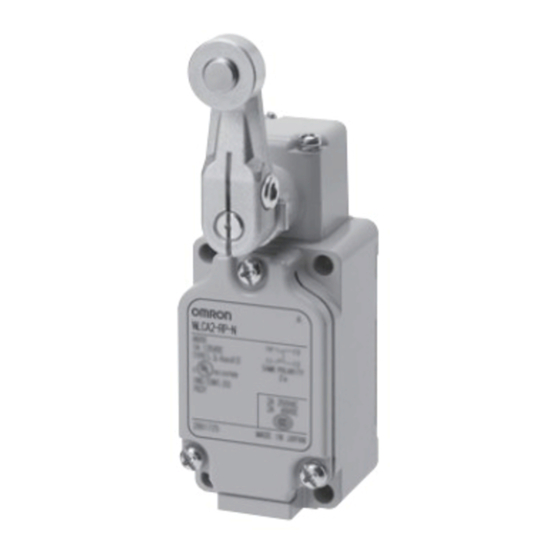
Environment-resistant Limit Switches
WL-N/WLG
Wide range of available models to
match your onsite environment
• Variety of head shapes, including Roller Lever, Plunger,
and Flexible Rod Switches
• Select the optimum actuator model for the ambient operating
temperature and operating environment for use in a wide
range of applications
• Wiring specifications are available in Direct-wire cable types
in addition to standard screw terminals types
Be sure to read Safety Precautions on pages 83 to 88 and
Safety Precautions for All Limit Switches.
Features
Select based on the operating temperature
Ambient operating temperature of 5°C to 120°C: Heat-resistant type (WL@-TH-N/WL@-TH)
Ambient operating temperature of -40°C to 40°C: Cold-resistant type (WL@-TC-N/WL@-TC)
Select based on the operating environment
Outdoor use: Weather-resistant type (WL@-P1-N/WL@-P1)
Chemicals and oils: Corrosion-resistant type (WL@-RP-N/WL@-RP)
Coolant drops and mist: Coolant-resistant type (WL@-RP60-N/WL-RP60)
Mist
Molded terminal 139 type (WL@-139-N/WL@-139)
The SC connector can be removed, so it is possible to use flexible conduit for the cable.
(WL@-RP40-N/WL-RP40)
Constant water drops and mist Molded terminal 140 type (WL@-140-N/WL@-140)
Constant water drops or splattering cutting powder
For the most recent information on models that have been certified for
safety standards, refer to your OMRON website.
Molded terminal 141 type (WL@-141-N/WL@-141)
Molded terminal 145 type (WL@-145-N/WL@-145)
33
Advertisement
Table of Contents

Related Manuals for Omron WL-N


Summary of Contents for Omron WL-N
- Page 1 For the most recent information on models that have been certified for safety standards, refer to your OMRON website. Be sure to read Safety Precautions on pages 83 to 88 and Safety Precautions for All Limit Switches.
-
Page 2: Model Number Structure
WL-N/WLG Model Number Structure Model Number Legend (Not all combinations are possible. Ask your OMRON representative for details.) Basic models WL@ - @ @ @ @ @ @ -N (2) (3) (4) (5) (6) (7) (5) Wiring and Built-in Switch Specifications... - Page 3 WL-N/WLG High-sensitivity and High-precision Models WLG@ - @ @ @ @ @ @ (2) (3) (4) (5) (6) (7) (1) Actuator and Property Specifications (5) Wiring and Built-in Switch Specifications Pretravel Built-in Code Actuator Terminal (PT) Code switch Mold specifications...
-
Page 4: Roller Lever
NO wiring WLG2-140LD3 * NC wiring WLCA2-141LD2-N 15±5° WLCA2-141-N NO wiring WLCA2-141LD3-N Molded terminal -141 NC wiring WLG2-141LD2 +2° 10° WLG2-141 -1° NO wiring WLG2-141LD3 +2° 5° WLGCA2-141 NO wiring WLGCA2-141LD3 * Ask your OMRON representative for details on Two-core switches. - Page 5 WL-N/WLG Without operation Built-in switch specification/ Pretravel indicator Apperance Actuator Terminal shape Temperature Specifications (PT) Model 15±5° WLCA12-TH-N 25±5° WLCA12-2TH-N Heat-resistant type 20° max. WLCA12-2NTH-N +2° 10° WLG12-TH -1° 15±5° WLCA12-TC-N 25±5° WLCA12-2TC-N Screw terminals Cold-resistant type (Conduit size: G Adjustable 20°...
- Page 6 WL-N/WLG Flexible Rod Without operation indicator Built-in switch specification/ Apperance Actuator Terminal shape Pretravel (PT) Temperature Specifications Model Heat-resistant type WLNJ-TH-N Screw terminals Cold-resistant type WLNJ-TC-N (Conduit size: G Corrosion-resistant type WLNJ-RP-N Coil spring (6.5 dia.) 20±10 mm Coolant-resistant type...
-
Page 7: Specifications
WL-N/WLG Specifications Ratings Screw terminals/Direct-wire cable Without Operation Indicator High-sensitivity and High-precision models (WLG) Basic models (WL-N) Non-inductive load (A) Non-inductive load (A) Inductive load (A) High-sensitivity and Ratings Basic models (WL-N) Basic models (WL-N) Ratings High-precision models (WLG) Resistive load... - Page 8 Note: The above figures are initial values. *1. The values are calculated at an operating temperature of +5°C to +35°C, and an operating humidity of 40% to 70%RH. Contact your OMRON sales representative for more detailed information on other operating environments.
- Page 9 WL-N/WLG Structure and Nomenclature Mold Specifications : Molded parts Prevent entry of foreign objects from Prevent entry of foreign objects from Prevent entry of foreign objects from conduit conduit cover head and conduit cover WL@-139-N WL@-140-N WL@-141-N Head cap Standard...
-
Page 10: Operating Characteristics
WL-N/WLG Dimensions (Unit: mm) Roller Lever Screw terminals Roller lever R38 Roller lever R38 Heat-resistant type Heat-resistant type WLG2-TH WLCA2-TH-N WLCA2-2TH-N WLGCA2-TH WLCA2-2NTH-N Cold-resistant type Cold-resistant type WLG2-TC WLGCA2-TC WLCA2-TC-N WLCA2-2TC-N Corrosion-resistant type WLCA2-2NTC-N WLG2-RP Corrosion-resistant type WLGCA2-RP WLCA2-RP-N Weather-resistant type 60 max. - Page 11 WL-N/WLG Direct-wire cable Roller lever R38 Roller lever R38 With operation indicator Coolant-resistant type Coolant-resistant specifications WLCA2-RP60-N WLCA2-RP60LD2-N WLCA2-2RP60-N WLCA2-RP60LD3-N WLCA2-2RP60LD2-N Molded terminal-139 60 max. 60 max. WLCA2-2RP60LD3-N WLCA2-139-N ±1.5 ±1.5 41.5 ±1.5 17.5×7 dia. * WLCA2-2139-N Molded terminal -139 41.5...
- Page 12 WL-N/WLG Roller lever R38 Roller lever R38 With operation indicator Coolant-resistant type Coolant-resistant specifications WLG2-RP60 WLG2-RP60LD2 Molded terminal -139 WLG2-RP60LD3 WLG2-139 WLGCA2-RP60LD2 WLGCA2-RP60LD3 60 max. 60 max. ±1.5 Molded terminal -139 ±1.5 41.5 ±1.5 41.5 ±1.5 17.5×7 dia. * WLG2-139LD3 17.5×7 dia.
- Page 13 WL-N/WLG Screw terminals Adjustable Roller Lever (R25 to 89 mm) Adjustable Roller Lever (R25 to 89 mm) Heat-resistant type Heat-resistant type WLCA12-TH-N WLG12-TH WLCA12-2TH-N Cold-resistant type WLCA12-2NTH-N WLG12-TC Cold-resistant type Weather-resistant type WLCA12-TC-N WLG12-P1 WLCA12-2TC-N Corrosion-resistant type 67 max. 67 max.
- Page 14 WL-N/WLG Direct-wire cable Adjustable Roller Lever (R25 to 89 mm) Adjustable Roller Lever (R25 to 89 mm) Molded terminal -140 Coolant-resistant specifications WLCA12-140-N WLCA12-RP60-N 67 max. Molded terminal -141 Molded terminal -139 ±1.5 17.5×7 dia. * WLCA12-141-N 67 max. WLCA12-139-N 41.5...
- Page 15 WL-N/WLG Plunger Actuators Screw terminals Sealed top-roller plunger Top-roller plunger Heat-resistant specifications Heat-resistant specifications WLD28-TH-N WLD2-TH-N Cold-resistant specifications WLD28-TC-N Corrosion-resistant specifications 13.1 WLD28-RP-N 13.1 17×4.6 dia. * 12.9 14.3×5 dia. * 12.9 4-M3.5 2-M3.5 28.4 Four, 5.2 dia. Four, 5.2 dia.
- Page 16 WL-N/WLG Direct-wire cable Sealed top-roller plunger Sealed top-roller plunger Coolant-resistant specifications Molded terminal -140 13.1 13.1 WLD28-RP60-N WLD28-140-N 14.3×5 dia. * 12.9 12.9 14.3×5 dia. * Molded terminal -139 2-M3.5 WLD28-139-N 2-M3.5 Four, 5.2 dia. holes Four, 5.2 dia. 58.7 58.7...
- Page 17 WL-N/WLG Flexible Rod Screw terminals Coil spring Resin rod Heat-resistant specifications Corrosion-resistant specifications WLNJ-TH-N WLNJ-2RP-N Cold-resistant specifications 8 dia. 6.5 dia. WLNJ-TC-N Corrosion-resistant specifications WLNJ-RP-N (95.4) (107) ±2.5 ±2.5 13.1 26 dia. 12.9 13.1 12.9 Two, M3.5 Two, M3.5 44.6 ±0.8...
-
Page 18: Coil Spring
WL-N/WLG Direct-wire cable Coil spring Coil spring Molded terminal -140 Coolant-resistant specifications WLNJ-140-N WLNJ-RP60-N 6.5 dia. Molded terminal -139 6.5 dia. WLNJ-139-N (107) (107) ±2.5 ±2.5 13.1 13.1 12.9 12.9 Two, M3.5 33.7 ±0.8 Two, M3.5 33.7 ±0.8 Four, 5.2 dia. -
Page 19: Ordering Information
WL-N/WLG Common Accessories (Sold Separately) Ordering Information Single-item ordering models ... . Switches without levers, heads, and actuators can be ordered separately. Use by combining with models that are not available as a set. You can also use them as maintenance parts for inventory management. - Page 20 Allen-head lever Neon lamp WLCA2-LES-N WLRCA2-LES-N WL-1A103S +2° 10° WLG2-LDS WLRG2-LDS -1° * The actuator is identical for the WL and WL-N models. Connector (Conduit size: JIS B0202G Inner External diameter Dimensions Applicable Application/ diameter (D) of cable Appearance (Unless otherwise indicated,...
- Page 21 WL-N/WLG Sensor I/O connectors AC/DC Number of cable Appearance Cable length (m) Cable model Compatible model type cores XS2F-A421-DB0-F WL@-@K13A-N WLG@-@K13A XS2F-A421-GB0-F WL@-@K43A-N for AC XS2F-A421-D90-F WL@-@-AGJ-N WLG@-@K43A XS2F-A421-G90-F WLG@-@-AGJ03 WL@-@K13-N XS2F-D421-DD0 WL@-@-M1J-N M12 Screw (Straight) WLG@-@K13 XS2F-D421-GD0 WLG@-@-M1J XS2F-D421-DA0-F...
-
Page 22: Wiring Diagram
Model Wiring Diagram Terminal No. Cable color of core sheath XS5F-D421-D80-F Brown XS5F-D421-G80-F White Blue Black Terminal Plate WL-N TERMINAL PLATE 3.7±0.1 dia. 12.5 14.7 R0.5 3.7±0.1 dia. Side mounting plate WLN-P001 Mounting Plate Plate mounting bolts (2) contents Switch mounting 30.2... - Page 23 WL-N/WLG SC-2F Built-in DC connector JIS B0202 G½ Brown (3) M4 crimp terminal Blue (4) M12 × 1 ±5 SC-2FAD Built-in AC connector JIS B0202 G½ Brown (3) M4 crimp terminal Blue (4) M12 × 1 ±5 SC-4F4AD Built-in AC connector JIS B0202 G½...
- Page 24 WL-N/WLG Actuators WL-1A100 WL-1A115 WL-1A400 WL-1A118 Standard Lever Resin Roller Bearing Roller Nylon Roller: Roller Width: 30 mm 17.5 dia. (length: 30) 17.9 17.9 16.9 40.2 ±0.8 17.5 dia. (length: 7) 17 dia. (length: 6) 17.5 dia. (length: 7) Nylon roller stainless sintered roller 12.6...
- Page 25 WL-N/WLG WL-2A100 WL-2A111 WL-2A107 WL-2A108 Resin Roller Double Nuts Resin Roller 24.9 ±0.8 17.5 dia. (length: 7) 24.9 ±0.8 24.9 ±0.8 17.5 dia. (length: 7) 24.9 ±0.8 17.5 dia. (length: 7) stainless sintered 19.7 ±0.8 19.7 ±0.8 19.7 17.5 dia. (length: 7) ±0.8...
- Page 26 WL-N/WLG WL-4A100 WL-4A201 WL-3A100 WL-3A106 Double Nut 3.2-dia. stainless 3.2-dia. 2-dia. stainless steel rod stainless 3-dia. stainless steel for spring steel rod steel rod Adjustable 7.3-dia. mounting from 350 holes 7.3-dia. Adjustable Adjustable to 380 Adjustable from 350 mounting from...
-
Page 27: Safety Precautions
WL-N/WLG Safety Precautions For the Safety Precautions for All Limit Switches, refer to the OMRON website. Meanings of Warning Signal Text Precautions for Correct Use Precautions Operating Environment Indicates an action that must be performed or for Safe Use avoided for safe use of this product. -
Page 28: How To Handle
For the WL-N, the P level is at the min. operating load of 5 VDC and arrowhead of the lever is positioned within the overtravel markers 1 mA resistive load. - Page 29 Microload Applications • The WL-N basic model, WLG high-sensitivity model, and high- precision model contacts can be used both for standard loads and microloads, but once a contact has been used to open and close a load, it can no longer be used for lower loads. Doing so will damage the contact surface and reduce contact reliability.
-
Page 30: Operation Procedures
WL-N/WLG Operation Procedures • Mount so that the actuator travel after operation (OT) is not exceeded. If the travel after operation (OT) exceeds the limit, Operation switch failure could result. When mounting the Limit Switch, be • Carefully determine the position and shape of the dog or cam so sure to adjust the Limit Switch carefully while considering the that the actuator will not abruptly snap back, thus causing shock. - Page 31 WL-N/WLG Using the Switches Item Applicable models and Actuators Details Changing the Installation Position of the Roller lever: Actuator (WLCA2-N, WLCA2-2-N, WLCA2-2N-N, By loosening the Allen-head bolt on the ac- WLG2, WLCA2-7-N, WLCA2-8-N, tuator lever, the position of the actuator can WLGCA2, WLMCA2-N, WLMG2, be set anywhere within the 360°.
- Page 32 WL-N/WLG Item Applicable models and Actuators Details Roller lever: Installing the Roller on the Inside (WLCA2-N, WLCA2-2-N, WLCA2-2N-N, By installing the roller lever in the opposite WLG2, WLCA2-7-N, WLCA2-8-N, direction, the roller can be installed on the in- WLGCA2, WLMCA2-N, WLMG2, side.
-
Page 33: Terms And Conditions Agreement
Data presented in Omron Company websites, catalogs and other materials is provided as a guide for the user in determining suitability and does not constitute a warranty. It may represent the result of Omron’s test conditions, and the user must correlate it to actual application requirements. - Page 34 The Netherlands Hoffman Estates, IL 60169 U.S.A. Tel: (31)2356-81-300/Fax: (31)2356-81-388 Tel: (1) 847-843-7900/Fax: (1) 847-843-7787 © OMRON Corporation 2017-2020 All Rights Reserved. OMRON (CHINA) CO., LTD. OMRON ASIA PACIFIC PTE. LTD. In the interest of product improvement, Room 2211, Bank of China Tower, No.