Table of Contents
Advertisement
Spyder
TM
VAV CONTROLLER
General ............................................................................... 3
Trademark Information .................................................... 3
Product Description........................................................... 3
Controller Part Numbers ................................................. 3
Dimensions ........................................................................... 4
Network Security ............................................................. 4
General Safety Instructions.......................................... 4
Specifications ................................................................... 5
Electrical ................................................................................ 5
Operational Environment................................................ 5
Hardware................................................................................ 5
Integrated Actuator..............................................................5
Communications ................................................................ 6
Modbus Client...................................................................... 6
Sylk™ Supported Devices................................................. 6
Differential Pressure Sensor .......................................... 6
Weight And Dimensions .................................................. 6
Universal IO........................................................................... 7
Solid State Relay (SSR)..................................................... 7
Wireless Connectivity........................................................ 7
Hardware overview ......................................................... 8
IP Model ................................................................................. 8
MSTP Model ......................................................................... 8
Service Button...................................................................... 9
Mounting ........................................................................... 9
Before Mounting Actuator .............................................. 9
Mounting Actuator onto Damper Shaft................... 10
Airflow Sensor Connection ........................................... 12
Recommendations........................................................... 12
Airflow Sensor Replacement ........................................ 13
Power supply.................................................................. 14
General Information ........................................................ 14
Power Wiring....................................................................... 14
Power Wiring Examples.................................................. 15
Input / Output Wiring ................................................. 16
Wiring Requirements ...................................................... 16
Internal Wiring Examples .............................................. 17
Terminal Connections..................................................... 18
UIO Wiring Examples ...................................................... 19
SSR (DO) Wiring Examples ........................................... 20
20 VDC Auxiliary Wiring Examples............................ 20
Network Concepts ........................................................ 21
® U.S. Registered Trademark
Copyright © 2022 Honeywell Inc. • All Rights Reserved
Model 7
INSTALLATION INSTRUCTIONS
The RS-485 Standard..................................................... 21
TIA/EIA 485 Cable Specifications .................................. 21
IP Network Topologies.................................................... 21
Daisy Chain......................................................................... 21
Ring Topology.................................................................... 21
BACnet IP Controller ................................................... 22
DHCP IP Configuration.................................................. 22
Link-local addressing..................................................... 22
Static IP Configuration .................................................. 22
Connect to a IP Network................................................ 22
WiFi (Future Release) .................................................. 22
Install the Local Antenna.............................................. 22
Install the Remote Antenna ......................................... 22
Remote Antenna Placement........................................ 23
BACnet MSTP Wiring................................................... 24
Termination Resistors .................................................... 24
RS-485 Bias Switches .................................................... 24
BACnet MSTP Wiring Example ................................... 24
BACnet MSTP Controller ............................................ 25
Automatic MAC Addressing ......................................... 25
Manual configuration of the MAC Address ........... 25
Configure the Device Instance Number.................. 26
Connect to the BACnet MSTP Network ................... 26
Modbus RTU................................................................... 27
Modbus Considerations ................................................ 27
Default Modbus values................................................ 27
Cables and Shielding...................................................... 27
Modbus RS-485 Repeaters.......................................... 27
Wiring Topology ................................................................ 27
Sylk™ Bus ........................................................................ 28
Supported Sylk bus devices ......................................... 28
Sylk bus Wiring Example............................................... 28
Bluetooth Balancing .................................................... 29
Overview .............................................................................. 29
Troubleshooting............................................................ 30
BACnet and Modbus LED Status............................... 30
Bluetooth LED Status..................................................... 31
Controller LED Status .................................................... 31
Regulatory Information .............................................. 32
FCC Regulation................................................................. 32
Canadian Regulatory Statement ............................... 32
Professional Installation Warning.................................. 32
Detachable Antenna Warning (IC) ................................. 32
31-00475-01
Advertisement
Table of Contents

Related Manuals for Honeywell Spyder 7


Summary of Contents for Honeywell Spyder 7
-
Page 1: Table Of Contents
SSR (DO) Wiring Examples ........... 20 Canadian Regulatory Statement ....... 32 20 VDC Auxiliary Wiring Examples......20 Professional Installation Warning........32 Detachable Antenna Warning (IC) ......... 32 Network Concepts ............21 31-00475-01 ® U.S. Registered Trademark Copyright © 2022 Honeywell Inc. • All Rights Reserved... - Page 2 SPYDER MODEL 7 VAV CONTROLLER INSTALLATION INSTRUCTIONS Standards and Compliance ......... 33 10 K3A1 Characteristics ............. 39 20 K NTC Characteristics ........... 42 Approvals and Certifications ........33 Nickel Class B DIN 43760 Sensors ........ 45 Article 33 Communication ..........33 NI1000 TK5000 DIN B............
-
Page 3: General
Inc. effective. • BACnet® is a registered trademark of ASHRAE Inc. • Sylk™ is a trademark of Honeywell International Inc. Spyder Model 7 offers BACnet IP or BACnet MSTP, Sylk™ bus technology, Modbus RTU RS-485, universal inputs Product Description and output (UIO), and solid-state relays. -
Page 4: Dimensions
• The Spyder™ Model 7 VAV controllers must be installed and mounted by authorized and trained personnel. • In the case of any modification, except by Honeywell, WARNING the operation and safety warranties become void. Honeywell hereby expressly states that the •... -
Page 5: Specifications
SPYDER MODEL 7 VAV CONTROLLER INSTALLATION INSTRUCTIONS SPECIFICATIONS Electrical Hardware Table 3 Electrical Specification Table 5 Hardware Specification Parameter Specification Parameter Specification Rated input Crossover processor NXP I.MRT, 20 - 30 VAC; Class 2 transformer voltage Cortex M7 IP model: 8 VA; controller and Memory 16 MB QSPI Flash, 16 MB SDRAM actuator load (nothing connected to... -
Page 6: Communications
SPYDER MODEL 7 VAV CONTROLLER INSTALLATION INSTRUCTIONS Communications Sylk™ Supported Devices Table 7 Communication Specification Table 9 Sylk™ Supported Devices Parameter Specification Parameter Specification BACnet IP, BACnet MSTP, TR40, TR40-H, TR40-CO2, TR40-H- Protocol supported Sylk™, Modbus RTU (Modbus Sylk™ wall CO2, TR42, TR42-H, TR42-CO2, client only), and BLE. -
Page 7: Universal Io
SPYDER MODEL 7 VAV CONTROLLER INSTALLATION INSTRUCTIONS Universal IO Solid State Relay (SSR) Table 12 Universal IO Specification Table 13 Solid State Relay (SSR) Parameter Specification Specification Solid state relay switches supply voltage and works Voltage: 0(2) to 10 VDC direct or with 24 ±... -
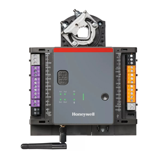
Page 8: Hardware Overview
SPYDER MODEL 7 VAV CONTROLLER INSTALLATION INSTRUCTIONS HARDWARE OVERVIEW IP Model TOP VIEW SIDE VIEW BOTTOM VIEW Fig. 3 IP Model Hardware Overview MSTP Model TOP VIEW SIDE VIEW BOTTOM VIEW Fig. 4 MSTP Model Hardware Overview 31-00475-01... -
Page 9: Service Button
SPYDER MODEL 7 VAV CONTROLLER INSTALLATION INSTRUCTIONS MOUNTING Service Button To mount the Spyder Model 7 VAV, refer to the mounting instructions provided with the controller. Before mounting the controller on the damper shaft, review the power, inputs and output specifications. See Specifications on page 5. -
Page 10: Mounting Actuator Onto Damper Shaft
SPYDER MODEL 7 VAV CONTROLLER INSTALLATION INSTRUCTIONS NOTE: NOTE: Mount the actuator flush with damper housing or The controller is not position sensitive and can be add a spacer between the actuator mounting sur- mounted sideways or upside down. Use the drill- face and damper box housing. - Page 11 SPYDER MODEL 7 VAV CONTROLLER INSTALLATION INSTRUCTIONS cator on the bracket represents approximately f. Tighten the two bolts on the centering clamp (8 6.5 ° of rotation per side. mm wrench; 70 lb. in. [8-10 Nm] torque). g. When the actuator closes, the damper rotates The declutch button, when pressed, allows you to counterclockwise (CCW) either 45 or 60 °...
-
Page 12: Airflow Sensor Connection
SPYDER MODEL 7 VAV CONTROLLER INSTALLATION INSTRUCTIONS Airflow Sensor Connection Differential Pressure Installation Recommendations Connect the airflow pickup to the two restrictor ports on the controller. The Spyder Model 7 VAV must be powered up for a minimum of an hour before performing the zero calibration. -
Page 13: Airflow Sensor Replacement
SPYDER MODEL 7 VAV CONTROLLER INSTALLATION INSTRUCTIONS Airflow Sensor Replacement Procedure to replace the airflow sensor is as follows: 1. Gently pull the sensor cover outward and rotate it by 75 °. Fig. 12 Removing the Airflow Sensor Cover 2. Disconnect the electrical connector by gently pulling it away from the differential pressure sensor. 3. -
Page 14: Power Supply
SPYDER MODEL 7 VAV CONTROLLER INSTALLATION INSTRUCTIONS POWER SUPPLY The 24 VAC power from an energy limited Class II power source must be provided to the controller. To conform to Class II restrictions (U.S. only), the transformer must not General Information be larger than 100 VA. -
Page 15: Power Wiring Examples
SPYDER MODEL 7 VAV CONTROLLER INSTALLATION INSTRUCTIONS Power Wiring Examples Power Wiring example for one Controller per Transformer UL Listed Class 2 Transformer 24 VAC 120 / 240 100 VA Earth Ground Spyder Model 7 Power Wiring example for two or more Controllers per Transformer UL Listed Class 2 Transformer 24 VAC... -
Page 16: Input / Output Wiring
SPYDER MODEL 7 VAV CONTROLLER INSTALLATION INSTRUCTIONS INPUT / OUTPUT WIRING Wiring Requirements NOTE: When attaching two or more wires to the same terminal, other than 14 AWG (2.0 mm ), be sure to twist them together. Deviation from this rule can result in improper electrical contact, see Fig. -
Page 17: Internal Wiring Examples
SPYDER MODEL 7 VAV CONTROLLER INSTALLATION INSTRUCTIONS Internal Wiring Examples IP Model Internal Wiring Fig. 16 IP Model Internal Wiring MSTP Model Internal Wiring Fig. 17 MSTP Model Internal Wiring 31-00475-01... -
Page 18: Terminal Connections
SPYDER MODEL 7 VAV CONTROLLER INSTALLATION INSTRUCTIONS Terminal Connections All the terminals for this controller are removable. Table 15 Terminal Connections Terminal Label Description Power 24 VAC Earth ground (connected to building earth ground) Power supply voltage (connected to 24 V0) Power supply voltage (connected to 24 VAC~) AC OUT 24 VAC~ output... -
Page 19: Uio Wiring Examples
SPYDER MODEL 7 VAV CONTROLLER INSTALLATION INSTRUCTIONS UIO Wiring Examples UO1 - UO7 Output Connection Example UIO1 - UIO7 Universal Input / Output (UIO) Output Type Load 0 to 10 VDC, 10 mA max. IN 0V 4 to 20 mA 0V IN 0V IN Voltage Output to Power External Relay... -
Page 20: Ssr (Do) Wiring Examples
SPYDER MODEL 7 VAV CONTROLLER INSTALLATION INSTRUCTIONS SSR (DO) Wiring Examples SSR Wiring with one Transformer and Factory Jumper UL Listed Class 2 Transformer 24 VAC 120 / 240 VAC Field 100 VA Devices Earth Ground SR1 - SR5 Solid State Relay (SSR) Spyder Model 7 SSR Wiring with Separate Transformer without Jumper Installed Field Device... -
Page 21: Network Concepts
(60 pF per meter) and Shield Multi Port (RSTP) Ethernet Switch The Honeywell tested and recommended MSTP cable is Honeywell Cable 3322 (18 AWG, 1-Pair, Shielded, Fig. 22 Ring Topology Plenum cable). Alternatively, Honeywell Cable 3251 (22 AWG, 1-Pair, Shielded, Plenum cable) is available and meets the BACnet Standard requirements. -
Page 22: Bacnet Ip Controller
SPYDER MODEL 7 VAV CONTROLLER INSTALLATION INSTRUCTIONS BACNET IP CONTROLLER WiFi (Future Release) The Spyder Model 7 VAV controllers have a local rubber DHCP IP Configuration antenna included in the packaging. If the Spyder Model 7 VAV controllers are mounted inside a cabinet or A new controller from the factory has DHCP enabled by enclosure, and you are using the local antenna, use an default. -
Page 23: Remote Antenna Placement
SPYDER MODEL 7 VAV CONTROLLER INSTALLATION INSTRUCTIONS 5. Tighten the wire terminal nut by turning the nut • Make sure thaìt the antenna is installed clockwise. Do not over-tighten. perpendicular to the surface for a good BLE signal. • The antenna has a strong signal transmission and reception from the side. -
Page 24: Bacnet Mstp Wiring
SPYDER MODEL 7 VAV CONTROLLER INSTALLATION INSTRUCTIONS BACNET MSTP WIRING Termination Resistors Matched terminating resistors are required at each end The MSTP variants of the Spyder Model 7 VAV controller of a segment bus wired across (+) and (-). Use matched use the BACnet MSTP communication protocol. -
Page 25: Bacnet Mstp Controller
SPYDER MODEL 7 VAV CONTROLLER INSTALLATION INSTRUCTIONS The polling process includes searching for new clients NOTE: with MAC addresses lying between their own MAC The 120 Ω termination resistor must be inserted address and that of the next client. directly into the terminals of both end devices. The property Max Master specifies the highest- allowable address for client nodes. -
Page 26: Configure The Device Instance Number
Number Use the Honeywell tested and recommended MSTP The Device Instance number must be unique across the cable - Honeywell Cable 3322 (18 AWG, 1-Pair, entire BACnet network because it uniquely identifies the Shielded, Plenum cable). Alternatively, Honeywell Cable BACnet devices. It may be used to distinguish the 3251 (22 AWG, 1-Pair, Shielded, Plenum cable) is BACnet device from other devices during installation. -
Page 27: Modbus Rtu
Modbus RS-485 Repeaters 4.8 kb/s (because these communication rates are not market-relevant). RS-485 repeaters are possible but have not been tested by Honeywell; therefore, it is the installing or commissioning person's responsibility to ensure proper NOTE: operation. The recommended number of Modbus servers is 8, with a maximum of 155 read / write data points. -
Page 28: Sylk™ Bus
SPYDER MODEL 7 VAV CONTROLLER INSTALLATION INSTRUCTIONS SYLK™ BUS Table 22. Recommended maximum distances Standard Non- Sylk™ Bus compatible wall modules such as TR120 can twisted Thermostat Single Twisted Pair, Non- be connected to the controller's Sylk™ (terminals 14 and Wire Shielded or shielded, Stranded or Solid 15). -
Page 29: Bluetooth Balancing
The antenna facilitates wireless communication via Bluetooth with other devices. Overview The Honeywell Connect Mobile (HCM) is a mobile application used for VAV balancing. The HCM app provides easy access to the Spyder Model 7 VAV controller via integrated Bluetooth. Make sure that the Spyder Model 7 VAV controller has a strong Bluetooth signal before connecting to the Honeywell Connect Mobile VAV Balancing app. -
Page 30: Troubleshooting
SPYDER MODEL 7 VAV CONTROLLER INSTALLATION INSTRUCTIONS TROUBLESHOOTING The controller features the following LEDs. BACnet Modbus Status Tx1 & Rx1 Tx2 & Rx2 WiFi (for future use) See Table “LED light status”, “Bluetooth LED Status”, and “BACnet and Modbus LED Status” below. Fig. -
Page 31: Bluetooth Led Status
SPYDER MODEL 7 VAV CONTROLLER INSTALLATION INSTRUCTIONS Bluetooth LED Status Table 25 Bluetooth LED Status Mode LED Status Visual BLE disabled by user BLE normal operation Green, permanently ON. and connected BLE enabled but not Green, 2 blinks in 1 s followed by connected 2 s pause, and repeat. -
Page 32: Regulatory Information
SPYDER MODEL 7 VAV CONTROLLER INSTALLATION INSTRUCTIONS REGULATORY INFORMATION CE Statement: The WLAN function for this device is restricted to indoor use only when operating in the 5150 to 5350 MHz frequency range. FCC Regulation This device complies with Part 15 of the FCC Rules. Operation is subject to the following two conditions: (1) this device may not cause harmful interference, and (2) this device must accept any interference received,... -
Page 33: Standards And Compliance
SPYDER MODEL 7 VAV CONTROLLER INSTALLATION INSTRUCTIONS Honeywell takes compliance with REACH very seriously. According to Article 33, “Duty to communicate Table 27 BLE Certification Numbers information on substances in articles”: FCC ID IC ID • Any supplier of an article containing a substance... -
Page 34: Appendix
SPYDER MODEL 7 VAV CONTROLLER INSTALLATION INSTRUCTIONS APPENDIX Sensor Input Accuracy The controller's internal sensor inputs support both 10 K NTC Ω and 20 K NTC Ω sensors. The following table lists the typical minimum accuracies of the hardware and software for these temperature sensors. Table 29 Sensor Accuracies Range Measurement Error (Excluding Sensor Characteristics) -
Page 35: Recognition Of Sensor Failure Of Sensor Inputs
SPYDER MODEL 7 VAV CONTROLLER INSTALLATION INSTRUCTIONS Recognition of Sensor Failure of Sensor Inputs The thresholds at which the sensor fails, that is, sensor breaks (SB) and short-circuits (SC), are recognized, depending upon the given sensor type. In the event of a recognized sensor failure, the sensor assumes the safety values configured in Table 29 on page 34. -
Page 36: Sensor Characteristics
SPYDER MODEL 7 VAV CONTROLLER INSTALLATION INSTRUCTIONS Sensor Characteristics The characteristics (resistance in relation to temperature) of the sensors and the resultant voltage are listed on the following pages. The stated values do not include failures due to sensor failures, wiring resistance or wiring failures, misreadings due to a meter connected to measure resistance or voltage at the input. - Page 37 SPYDER MODEL 7 VAV CONTROLLER INSTALLATION INSTRUCTIONS Table 31 10 K NTC TYPE II Characteristics (Continued) Terminal Terminal Temp. Temp. Resistance Temp. Temp. Resistance Voltage Voltage [°F] [°C] [KΩ] [°F] [°C] [KΩ] 93.2 6.808 2.091 159.8 1.694 0.632 6.531 2.025 161.6 1.637 0.612...
-
Page 38: 10 K Ntc Type Iii Characteristics
SPYDER MODEL 7 VAV CONTROLLER INSTALLATION INSTRUCTIONS 10 K NTC TYPE III Characteristics Table 32 10 K NTC TYPE III Characteristics Temp. Temp. Temp. [°F] Resistance [Ω] Temp. [°F] Resistance [Ω] [°C] [°C] -37.2 203.6K 40.6 5479 -34.4 173.6K 43.3 4947 -31.7 148.3K... -
Page 39: 10 K3A1 Characteristics
SPYDER MODEL 7 VAV CONTROLLER INSTALLATION INSTRUCTIONS 10 K3A1 Characteristics Table 33 10 K3A1 Characteristics Temp. Temp. Resistance Temp. Temp. Resistance [°F] [°C] [Ω] [°F] [°C] [Ω] 336098 26.6 38110 -38.2 314553 28.4 36184 -36.4 294524 30.2 34366 -34.6 275897 32651 -32.8 258563... - Page 40 SPYDER MODEL 7 VAV CONTROLLER INSTALLATION INSTRUCTIONS Table 33 10 K3A1 Characteristics (Continued) Temp. Temp. Resistance Temp. Temp. Resistance [°F] [°C] [Ω] [°F] [°C] [Ω] 93.2 6807 159.8 1693 6530 161.6 1637 96.8 6266 163.4 1582 98.6 6014 165.2 1530 100.4 5774 1480...
- Page 41 SPYDER MODEL 7 VAV CONTROLLER INSTALLATION INSTRUCTIONS Table 33 10 K3A1 Characteristics (Continued) Temp. Temp. Resistance Temp. Temp. Resistance [°F] [°C] [Ω] [°F] [°C] [Ω] 226.4 242.6 228.2 244.4 246.2 231.8 233.6 249.8 235.4 251.6 237.2 253.4 255.2 240.8 31-00475-01...
-
Page 42: 20 K Ntc Characteristics
SPYDER MODEL 7 VAV CONTROLLER INSTALLATION INSTRUCTIONS 20 K NTC Characteristics Table 34 20 K NTC Characteristics Temp. Temp. Resistance Terminal Temp. Temp. Resistance Terminal [°F] [°C] [KΩ] voltage [V] [°F] [°C] [KΩ] Voltage [V] 1659 8.78 7.83 -56.2 1541 8.77 7.78 -54.4... - Page 43 SPYDER MODEL 7 VAV CONTROLLER INSTALLATION INSTRUCTIONS Table 34 20 K NTC Characteristics (Continued) Temp. Temp. Resistance Terminal Temp. Temp. Resistance Terminal [°F] [°C] [KΩ] voltage [V] [°F] [°C] [KΩ] Voltage [V] 25.3 4.75 134.6 5.08 1.66 69.8 24.2 4.64 136.4 4.88 1.61...
- Page 44 SPYDER MODEL 7 VAV CONTROLLER INSTALLATION INSTRUCTIONS Table 34 20 K NTC Characteristics (Continued) Temp. Temp. Resistance Terminal Temp. Temp. Resistance Terminal [°F] [°C] [KΩ] voltage [V] [°F] [°C] [KΩ] Voltage [V] 199.4 0.527 251.6 0.57 0.225 201.2 1.35 0.511 253.4 0.56 0.219...
-
Page 45: Nickel Class B Din 43760 Sensors
SPYDER MODEL 7 VAV CONTROLLER INSTALLATION INSTRUCTIONS Nickel Class B DIN 43760 Sensors T(R) = a´+b´(1+c´R)½ +d´R5+e´R7 dT < 0.12 K (higher order equations on request) The characteristic of the nickel temperature sensor is specified as per DIN 43760. The large Temperature Coefficients: Coefficient of Resistance (TCR) of the Ni-RTD, 6178 ppm/K, offers greater sensitivity than other types of... -
Page 46: Ni1000 Tk5000 Din B
SPYDER MODEL 7 VAV CONTROLLER INSTALLATION INSTRUCTIONS NI1000 TK5000 DIN B R-T Characteristics of Ni1000 TK5000 DIN B. Table 36 NI1000 TK5000 Sensor Specification Sensor Type Nominal Resistance Sensitivity : 1000 Ω Ni1000 TK5000 DIN B TC: 5000 ppm/K Table 37 R-T Characteristics (according to supplier‘s specifications and based on DIN 43760, resistance values in Ω) Temp. -
Page 47: Pt100 Characteristics
SPYDER MODEL 7 VAV CONTROLLER INSTALLATION INSTRUCTIONS PT100 Characteristics Table 38 PT100 Characteristics Temp. [°F] Temp.[°C] Resistance [Ω] -34.44 -28.89 -23.33 -17.78 -12.22 -6.67 -1.11 0.00 4.44 10.00 15.56 21.11 25.00 26.67 32.22 37.78 43.33 48.89 54.44 60.00 65.56 71.11 76.67 82.22 87.78... -
Page 48: Pt1000 Characteristics
SPYDER MODEL 7 VAV CONTROLLER INSTALLATION INSTRUCTIONS PT1000 Characteristics Table 39 PT1000 Characteristics Terminal Temp. Temp. Resistance Terminal Temp. Temp. Resistance Voltage [°F] [°C] [KΩ] Voltage [V] [°F] [°C] [KΩ] 0.312 0.367 -56.2 0.314 10.4 0.369 -54.4 0.315 12.2 0.37 -52.6 0.317 0.372... - Page 49 SPYDER MODEL 7 VAV CONTROLLER INSTALLATION INSTRUCTIONS Table 39 PT1000 Characteristics (Continued) Terminal Temp. Temp. Resistance Terminal Temp. Temp. Resistance Voltage [°F] [°C] [KΩ] Voltage [V] [°F] [°C] [KΩ] 75.2 1093 0.42 145.4 1244 0.476 1097 0.422 147.2 1248 0.477 78.8 1101 0.423...
- Page 50 SPYDER MODEL 7 VAV CONTROLLER INSTALLATION INSTRUCTIONS Table 39 PT1000 Characteristics (Continued) Terminal Temp. Temp. Resistance Terminal Temp. Temp. Resistance Voltage [°F] [°C] [KΩ] Voltage [V] [°F] [°C] [KΩ] 215.6 1393 0.53 1536 0.581 217.4 1396 0.531 285.8 1539 0.582 219.2 1400 0.532...
- Page 51 SPYDER MODEL 7 VAV CONTROLLER INSTALLATION INSTRUCTIONS Table 39 PT1000 Characteristics (Continued) Terminal Temp. Temp. Resistance Terminal Temp. Temp. Resistance Voltage [°F] [°C] [KΩ] Voltage [V] [°F] [°C] [KΩ] 352.4 1677 0.631 420.8 1817 0.68 354.2 1681 0.632 422.6 1821 0.681 1685 0.634...
- Page 52 SPYDER MODEL 7 VAV CONTROLLER INSTALLATION INSTRUCTIONS Table 39 PT1000 Characteristics (Continued) Terminal Temp. Temp. Resistance Terminal Temp. Temp. Resistance Voltage [°F] [°C] [KΩ] Voltage [V] [°F] [°C] [KΩ] 489.2 1955 0.728 557.6 2092 0.775 1959 0.729 559.4 2095 0.776 492.8 1962 0.73...
- Page 53 SPYDER MODEL 7 VAV CONTROLLER INSTALLATION INSTRUCTIONS Table 39 PT1000 Characteristics (Continued) Terminal Temp. Temp. Resistance Terminal Temp. Temp. Resistance Voltage [°F] [°C] [KΩ] Voltage [V] [°F] [°C] [KΩ] 2226 0.821 690.8 2353 0.863 627.8 2230 0.822 692.6 2356 0.864 629.6 2234 0.823...
-
Page 54: Pt3000 Characteristics
SPYDER MODEL 7 VAV CONTROLLER INSTALLATION INSTRUCTIONS PT3000 Characteristics Table 40 PT3000 Characteristics Terminal Temp. Temp. Resistance Terminal Temp. Temp. Resistance Voltage [°F] [°C] [KΩ] Voltage [V] [°F] [°C] [KΩ] 2.82 1.02 3.74 1.31 2.87 1.03 3.78 1.32 2.91 1.05 3.83 1.33 2.96... -
Page 55: Abbreviations
The material in this document is for information purposes only. The content and the product described are subject to change without notice. Honeywell makes no representations or warranties with respect to this document. In no event shall Honeywell be liable for technical or editorial omissions or mistakes in this document, nor shall it be liable for any damages, direct or incidental, arising out of or related to the use of this document.